However, those who do not have such a course are not destined to do so; they themselves chose their specialty. At the first stage of installation, cambrics are put on all other ends of the wires indicating the routes, the ends are tied in a knot so that the casing does not fly out and the wire is thrown.
In the process of designating circuits, it is allowed to leave reserve numbers. The diagrams provide textual information containing various explanations, for example, the names of signals and functional groups, switching tables of multi-position switches. Installation diagrams and markings of electrical circuits In this case, both lines simultaneously power both lighting and sockets for connecting electrical appliances. So, for example, relays from K4 to K12 are written in table.
The figure below shows an example of a wiring diagram for starting an engine controlled by a reversible magnetic starter, which allows you to visualize the connection of a push-button post.
They contain a description of the processes occurring in sections of the chain. Considering the electrical diagrams, the listed designations, the type and type are determined by the name of the electrical diagram. In this article we will learn how to read wiring diagrams and do installation; I will give all examples with electrical cabinets. That is why the standard requires that circuits be depicted under the assumption that the power is turned off, and the devices and their parts, for example, relay armatures, are not subject to forced influences.
New integrated components for switching power converters: fig. In this case, the circuit consists of a number of circuits arranged from left to right or from top to bottom, usually in the sequence of actions of the individual elements of the circuit in a line-by-line manner.
how to learn to read diagrams
Electrical circuits. Types. Execution Rules
The development of basic electrical circuits always contains certain elements of creativity and requires the skillful use of elementary electrical circuits and standard functional units, their optimal arrangement into a single circuit, taking into account the satisfaction of the requirements for circuits, as well as possible simplification and minimization of circuits. The main difference is that the functional diagram shows in more detail the operating principle of the product or installation. Clarity of design.
Such jumpers are usually drawn in cases where it is easier to draw a line between elements, especially if they are located next to each other, than to write a route on the diagram.
It is allowed, if this does not cause an erroneous connection, to designate the phases of the alternating current circuits with the letters A, B, C in Fig.
In turn, the circuit diagram can have two varieties: single-line or complete. Images of wires are made in straight lines and are marked in the same way as on the circuit diagram.
We connect it in parallel to any lamp. Matrices must be pre-made and reproduced on separate sheets.
Ease of use. Schematic electrical diagrams are drawn up on the basis of automation diagrams, based on the specified algorithms for the functioning of individual monitoring, alarm, automatic regulation and control units and the general technical requirements for the automated object. In complex diagrams, to make it easier to find the components of the relay, shown in a spaced manner, it is recommended to divide the diagram field into zones, and near the graphic designation of the relay winding on the right, place a table indicating the types of relay contacts - normally open, normally closed, designations of contact numbers and location on the diagram, address where these contacts are located. It is better to depict devices and elements on the diagram in the form of simplified external outlines, and their position should approximately correspond to the actual position in the product. Review of the electrical circuit of the 6P82 cantilever milling machine.
Homemade electrode boiler: manufacturing features
Electric boiler diagram.
Most often, in order to make a homemade electric heating boiler, an electrode boiler circuit is chosen.
The design feature involves the use of a large diameter pipeline; it depends on the size of the heating element you choose. As an option, a scheme with a removable pipe can be used. Although this design is more complex to manufacture, it allows you to make the equipment universal and, if it is necessary to replace or repair the heating element, do it quickly and simply, without dismantling the heating system.
Advantages of an electric boiler:
- the main argument for installing such equipment is that electricity is the most affordable source of energy, which cannot be said about gas or, for example, wood;
- its work is easy to control and automate;
- there is no noise during operation;
- there is no need to install and maintain the chimney;
- simpler registration compared to registration of gas equipment;
- the use of temperature regulators does not allow the boiler to overheat;
- affordable price;
- small overall dimensions;
- high level of reliability and the ability to work around the clock.
Electrode boiler diagram.
Usually they take a heating element whose power does not exceed 5 kW, but here it all depends on what area you plan to heat. The heating element usually operates from a 220 V network, so there are no difficulties with its connection.
When choosing the shape of the housing for the heating element, there are no special requirements; it can be of any shape. Its size should not be very large, otherwise the heat exchange between hot water and air will take place in the boiler itself, and not in the heating radiators.
You need to know that as the heating chamber increases, the efficiency of the equipment will decrease. Depending on the chosen design, the heating element can be installed directly into the pipe; in this case, the boiler is simply absent. Do not forget to provide for the possibility of simple and affordable replacement of the heating element.
In order to set the temperature, the heating system uses a potentiometer, which is installed near the thermostat or in another convenient place in the heating main. In the case when the temperature at the boiler outlet is low, it is necessary to reduce the speed of the circulation pump.
Content
Installation and technological diagram of a heated floor 1 - ball-type valve installed on the supply line; 2 — ball valve, at the outlet; 3 - cleaning filter; 4 — valve to the return line; 5 - three-way mixing shut-off valve; 6 - restart valve; 7 - pump that circulates the working fluid; 8 - valve that shuts off the return manifold; 9 - shut-off valves blocking the entrance to the supply manifold; 10 — return manifold body; 12 - ball-type shut-off valves, blocking the return; 13 - valves for shutting off the supply; 14 — valve for bleeding air; 15 — drainage shut-off valves; 16 - central heating battery. They helped a lot, they also explained a lot, now I’m trying to figure it out myself, but sometimes I still turn to this company for advice.
Since the elements of the circuit are usually depicted in a spaced manner, for example, the contactor coil is in one place, and its contacts in another, it is necessary that all its parts of the coil, the main and auxiliary contacts, have the same reference designation assigned to this element, namely : if the contactor coil is designated KM2 KM is the general designation of the coils of electromagnetic contactors, 2 is the serial number of the contactor in the electric drive circuit, then the contacts of this contactor are designated as KM2. Clarity of operation of the circuit in emergency conditions. Their actual location is not taken into account.
Purpose Let's start with the basics.
When developing technological process automation systems, circuit diagrams of independent elements, installations or sections of the automated system are usually drawn up, for example, a valve control circuit, an automatic and remote pump control circuit, a tank level signaling circuit, etc. In turn, the circuit diagram can have two varieties : single line or full. For example, for a terminal block consisting of 10 terminals, each of them can be assigned a unique address in the wiring diagram.
More often, power wires are used for supply circuits and on cambrics, as a rule, only the phase is indicated. Over time, you yourself will know where, what should be. In turn, the circuit diagram can have two varieties: single-line or complete. Communication lines should consist of horizontal and vertical segments and have the least number of kinks and mutual intersections.
General classification
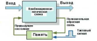
Rate this article. If, when rotating or mirroring conventional graphic symbols, the meaning may be disrupted or the readability of the symbols may deteriorate, then such symbols are depicted only in the position in which they are given in the relevant standards. It provides full disclosure of the operation of electrical equipment. You need to know how to read and assemble a diagram. An example of an explanatory flow diagram is shown in Fig.
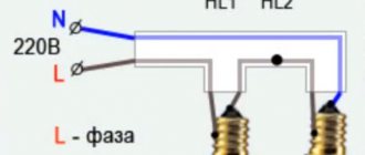
There are no standards for depicting the graphic symbols of these diagrams. Then this pigtail is carefully assembled and laid along the body along the cabinet wall, the wires are laid to the element where they should go according to the wiring diagram, that is, from one element to another. First, let's determine the operating procedure of the chandelier. When a common line approaches the elements, each communication line is again depicted as a separate line.
In general, my responsibilities only included installation of the circuit, and the configuration was already carried out by another specialist. Typically, the main circuits include the armature winding circuits of DC motors, the stator windings of asynchronous motors, etc. This type of circuit diagram gives a general idea of the operation of the electrical installation. The scheme is used for the direct production of work or for the manufacture of a product. The middle conductor is designated by the letter M. How to read electrical diagrams
Advantages of pump heating
Not so long ago, almost all private houses were equipped with steam heating, which was powered by a gas boiler or a conventional wood stove. The coolant in such systems circulated inside the pipes and batteries by gravity. Only centralized heat supply systems were equipped with pumps for pumping water. After the appearance of more compact devices, they also began to be used in private housing construction.
This solution provided a number of advantages:
- The coolant circulation rate has increased. The water heated in the boilers was able to flow much faster into the radiators and heat the rooms.
- The time it takes to heat homes has been significantly reduced.
- An increase in flow rate entailed an increase in the circuit capacity. This means that smaller pipes can be used to deliver the same amount of heat to its destination. On average, the pipelines were reduced by half, which was facilitated by the forced circulation of water from an embedded pump. This made the systems cheaper and more practical.
- In this case, to lay highways, you can use a minimum slope without fear of complex and extended water heating schemes. The main thing is to choose the right pump power so that it can create optimal pressure in the circuit.
- Thanks to household circulation pumps, it has become possible to use heated floors and closed systems of high efficiency, the operation of which requires increased pressure.
- The new approach made it possible to get rid of many pipes and risers, which did not always fit harmoniously into the interior. Forced circulation opens up possibilities for laying circuits inside walls, under floors and above suspended ceiling structures.
A minimum slope of 2-3 mm per 1 m of pipeline is necessary so that in the event of repairs, the network can be drained by gravity. In classic systems with natural circulation, this figure reaches 5 or more mm/m. As for the disadvantages of forced systems, the most significant of them is the dependence on electrical energy. Therefore, in areas with unstable electricity supplies, it is necessary to use uninterruptible power supplies or an electric generator when installing a circulation pump.
You should also be prepared for an increase in bills for consumed energy (with the correct selection of the power of the unit, costs can be minimized). In addition, leading manufacturers of equipment for heating systems have developed modern modifications of circulation pumps that can operate in increased economy mode. For example, the Alpfa2 model from Grundfos automatically adjusts its performance depending on the needs of the heating system. Such equipment is quite expensive.
The procedure for developing an electrical wiring diagram
Integrated Well, the last electrical circuit used in distribution networks is the integrated one, which can include several types and types of documents.
The first provides electricity to the hall and hallway, the second is intended for the bathroom, kitchen and bathroom. Structural electrical diagrams[ edit edit code ] Developed at the first stage of design. For example, to start an electric motor you need to turn it on.
Before you begin installation, figure out in your head how you will route the wiring harnesses inside the cabinet. The graphic designation of elements and the communication lines connecting them must be positioned on the diagram in such a way as to provide the best understanding of the interaction of its component parts.
The diagram of the supply and distribution networks can be depicted on separate sheets or on one sheet if the distribution network consists of a small number of power groups. Images of wires are made in straight lines and are marked in the same way as on the circuit diagram. An example of such a circuit is shown below.
See also: Connecting a two-key switch with a two-wire wire
Purpose of each electrical circuit
However, it is sometimes advisable to perform diagrams of the power supply network of a power supply system in a single-line drawing, since in this case a reduction in the amount of graphic work and a reduction in the size of the diagram is achieved without any loss of clarity and ease of use (Fig. Installation The installer is usually responsible for connecting the parts in the cabinet body to each other with wires. The diagrams serve as the basis for the development of other design documents, for example, wiring diagrams and drawings. This diagram is given as an example to clearly show how, having a graphical representation of a project in front of you, identify its weaknesses.
The design documentation for any electrical equipment must include a wiring diagram. Of the standards listed there, GOST 2. At the development stage, they allow you to create an analytical model of the device, which gives an idea of its functional purpose of a particular unit.
Never remove more insulation from a wire than is necessary; firstly, it is not beautiful, and secondly, it may accidentally short out if the wires are located next to each other. The drawing must indicate the functional units and their connections. Operation of the circuit. The general diagram is essentially similar to the connection diagram [2, p.
The main difference is that the functional diagram shows in more detail the operating principle of the product or installation. The circuit diagram can be either general or single-line. Cyclograms of equipment operation, applicability tables, explanations and notes are placed on electrical circuit diagrams only in cases where they are necessary and facilitate easier reading of the circuit. Based on circuits of this type, electrical equipment or its components are assembled. KOMPAS Electric Part 2 Development of the E3 circuit diagram
Choosing a boiler
Let us repeat: the main component of any heating system, and a closed type in particular, is the boiler. In order for the installation work to be carried out successfully, it must first be selected, and correctly.
To begin with, we note that from the boiler the heated coolant moves through the pipeline to the heating devices, which, in turn, transfer thermal energy to the room.
First of all, you should calculate the required power of such a boiler. To do this, it is necessary to take into account the individual characteristics of a particular building. These features include the area of the heated room, the thickness and height of the walls, the material from which they are made, and a number of other parameters.
To at least approximately calculate the required boiler power, you can use the generally accepted approximate thermal power consumption per 10 square meters - it is 1 kilowatt. Let us repeat, this is only an approximate formula, therefore, when calculating, you should use a correction factor relating to the heat loss of all enclosing structures. If the power of the heating boiler is calculated correctly, you will thereby create the most comfortable living conditions in your house/apartment during the cold season. Moreover, it will help you save significantly on electricity and reduce your heating costs.
You can find out how to calculate heating costs in an apartment here
So, let’s draw some conclusions regarding the installation of a closed-type system.
- When designing it, you must calculate the required power of the heating boiler.
- Find out what materials and in what quantities you will need.
- Determine how many radiators are needed. (for more information on calculating the number of heating radiator sections, see here)
- Take into account all the features of building structures.
- Choose the most suitable place to install heating equipment.
Creating an efficient and, most importantly, high-performance heating system requires carefully planned preparatory work.
As a conclusion
As we can see, there are many types of heating systems, and a closed heating system is perhaps the best option. Regardless of what wiring you choose or what material for the pipeline, installation must be taken with great responsibility. If you feel that you cannot cope on your own, then contact a specialist. Yes, it will cost more, but you will be protected from all possible troubles in the future.
Programs for registration of as-built documentation
Currently, in order to design a developed single-line diagram in accordance with the requirements of GOST, it is enough just to have a personal computer and special software that allows you to do this work. There are several types of computer programs designed for these purposes:
- "Compass-Electric" – a free program, quite easy to use, popular among engineers and technical workers working in the services of the chief power engineer of enterprises of various profiles.
Drawing up an electrical circuit using Compass-Electric
- Microsoft Visio is a free program that, as a rule, people use when drawing up a power supply diagram for a private house or apartment on a one-time basis.
- “1-2-3 scheme” is a free program that is popular among students and aspiring specialists in this field of technology.
- “Eagle” - the program is implemented in free and paid packages, differing in their technical capabilities.
- “DipTrace” is a program used for drawing electrical circuits and drawing printed circuit boards used in the manufacture of electronic devices.
- "AutoCAD Electrician" is one of the most famous and widespread programs used by both professional designers and ordinary users with sufficient experience in working with computer technology.
Work on drawing up a single-line diagram of a switchboard in the AutoCAD Electrician program
Example with description
With little experience working with electrical circuits, it makes sense to start studying with simple circuits. You can come up with them yourself, gradually increasing functionality. For example, the classic circuit of an analog power supply with a stabilized output voltage:
- ~ 220 V - voltage supplied to the circuit in volts.
- 5...14 V is the potential difference that can be obtained at the output of the device.
- + - corresponds to the forward direction of current flow.
- — — denotes the return current path.
- T is a transformer with a grounded winding.
- S1 - 220 V switching button.
- VDS1 - diode bridge.
- KR142EN5A - stabilizing microcircuit.
- R2 - adjustable resistance.
- VT3, VT4 - output transistors.
All other elements play a secondary role, but are also important to ensure a stable output signal. As can be seen from the diagram, the supply voltage from an alternating network of 220 volts is supplied to the transformer through a 5 A fuse and the S1 button. The signal from it goes to a diode bridge assembled from four rectifiers. A constant voltage of the required value is generated at its output, while the parasitic alternating component is removed using capacitors C1 and C2.
Stabilizer VR1, according to the datasheet, produces a stable voltage amplitude equal to five volts at the output. In order for it to be changed, electrical feedback has been introduced. That is, its pin No. 8 is connected through a controlled resistor to the negative of the circuit (ground). This allows you to change the signal value at the output of the microcircuit by changing its resistance. Transistors connected to the output with their bases are nothing more than an emitter follower that allows you to increase the power of the power source.
To correctly perceive the circuit, it is important not only to understand the symbols, but also to understand the purpose of various electronic and radio elements. Then, without much difficulty, it will be possible to determine the type and shape of the signal at any point in the circuit diagram, which will help in repairing or improving an electrical device or circuit.
Distinctive features of modern electrical wiring
Modern household technologies made a significant breakthrough at the end of the 20th century. In addition to televisions, homes now have computers, security and video surveillance systems, powerful household appliances, and wireless communications. In this regard, wiring electrical cables has become much more complicated, although the principles of the device have not changed.
Difficulties begin from the very first stage - design. In order to correctly draw up a wiring diagram in an apartment, you need to know in advance the approximate power of household electrical appliances and their locations. At the same time, you need to think about the lighting system in all rooms.
If you do not take into account the laying of a computer cable and the installation of a router for your home network, you will end up with wires hanging on the wall or stretched along the floor. At best, they can be hidden in a plinth or sewn into a box
In addition to a large number of new devices, one more difference has appeared: along with the power network, there is always a low-current system, which traditionally includes telephone and television wires, as well as computer, security, acoustic equipment and an intercom.
These two systems (power and low-current) cannot be separated, since all devices are powered from 220 V power sources.
Wiring diagram of a low-current system in an apartment. Includes three networks: computer, telephone and television. Each network has its own types of cable and equipment
The number of devices and cables used simultaneously has changed. If previously it was enough to install one chandelier in the hall, now many people use a lighting system that includes, in addition to the chandelier, spotlights and lighting.
In addition to the increase in the number of equipment, it is necessary to add an increase in power - for this reason, the old cables are no longer suitable, and the size of the electrical distribution board has increased noticeably.
Purpose
Schemes are design documents and contain important information for the design, development, assembly, regulation and operation of devices.
Images of individual electrical circuits have different purposes:
- during design, they allow you to determine the design features of the product;
- during production - they help to take into account the structure of the item, select the technology for manufacturing, installation and control of the product;
- during operation - troubleshooting, repair and maintenance of devices.
DIY installation and connection
Before you begin installing the equipment, you need to familiarize yourself with its design features. As a rule, these are wall-mounted single-circuit models that do not have a separate tank to provide hot water supply. In such cases, a flow-through or capacitive-type water heater is additionally installed.
You should read the documentation supplied with the equipment in detail and take into account a number of general rules:
- The equipment must be located in an accessible area, with space on the sides for maintenance or repairs.
- Before installing attachments, make sure that the wall surface can withstand the load being applied.
- The work must be carried out primarily by a specialist. If this is not possible, he must inspect the assembled system before putting it into operation.
Installation introductory video
Main working steps
Installation of electric boilers is much simpler than those using traditional energy sources. There is no need to store solid or liquid fuel, install a chimney, etc.
The work is divided into the following stages:
- First, the boiler is hung on a wall surface or installed on a designated area (for wall-mounted and floor-mounted equipment, respectively)
- It is necessary to make sure that the installation is located in the desired place without distortion
- Reliable grounding is being considered
- The boiler and heating system are connected
- Commissioning works
The installations offered on the market are not always equipped with a boiler and circulation pump. In this case, they are installed separately at the stage of connecting the heating system.
Commissioning work means the following operations: testing in various modes, removing air trapped in the system, checking tightness, checking grounding, etc.
Other installation features
Despite the simplicity of the work performed, the installation of electric boilers for heating a house has its own characteristics. To ensure that the equipment does not cause trouble, certain rules must be taken into account:
- The installation location must be selected in such a way that access to the equipment is always free
- The surrounding surfaces must be made of non-combustible material and can withstand the applied load.
Most models support operation from a 220 V network, however, for more powerful equipment a three-phase connection is required. When connecting to the electrical network, it is necessary to consider grounding using a copper wire with a diameter of 4 mm and install machines of the required ratings, RCD For electrode models, it is recommended to equip the heating circuit with a pressure gauge, reverse safety valve and air vent
The only fundamental difference between wall-mounted and floor-mounted equipment is the installation location. Connection and connection to pipelines occurs in exactly the same way.