August 24, 2011
Bulk Metal Foil technology was developed in 1962 by Dr. Felix Zandman, founder of Vishay. The company's work resulted in foil resistors with a low temperature coefficient of resistance (TCR) and high stability of parameters regardless of temperature changes [1]. Bulk Metal Foil technology introduced the company to the market of precision resistors and devices based on them and made it one of the clear leaders in this field.
Z-Foil technology successfully implemented in 2000, became a new breakthrough for Vishay. For the first time, an absolute TCR value of ±0.2 ppm/°C was achieved.
The company's development strategy [2] is focused on vertical integration of products - the use of technology for manufacturing foil resistors for sensors (resistance, strain, current, etc.); the use of sensors in electronic measuring devices; integration of sensors and electronic measuring devices, as well as software into modules and measuring systems.
Main properties of Vishay resistors and their range
Today, foil resistors are superior to other types of resistive components in accuracy, stability and reliability. All this became possible thanks to a unique design, including the use of a special resistive alloy (C-Foil, K-Foil, and since 2000 - Z-Foil), which provides unique properties - extremely low temperature and power resistance coefficients (TCR and MCR less than 10 ppm /°C) [3-5].
Typical technical characteristics of foil resistors:
- Low temperature coefficient of resistance: ±0.05ppm/°C (0...60°C), ±0.2 ppm/°C (-55...125°C);
- Wide range of rated power;
- High maximum operating voltage 180V;
- High accuracy ±0.01…0.001%;
- ISS as a result of self-heating 5ppm at rated power;
- Electrostatic protection up to 25 kV;
- Stability when operating under load ±0.005% (70°C, about 2000 hours of operation at rated power);
- Wide range of nominal resistances;
- Non-inductive, non-capacitive design;
- Low current noise values -40dB;
- Voltage ratio less than 0.1ppm/V;
- Operating temperature range -55…125°C;
- Possibility to produce ANY (1K892346) rating within the resistance ratings of this series.
The company offers precision resistors for almost any application, in any design [3, 5]. The range of foil resistors (Table 1) includes:
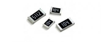
- Surface Mount Resistors (SMD);
- Discrete resistors for through-hole mounting;
- Voltage dividers (through-hole and SMD);
- Resistor assemblies (for through-hole and SMD mounting);
- Current-sensing resistors;
- Sealed resistors;
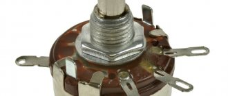
- Potentiometers;
- Hybrid chips;
- Sealed resistor assemblies to customer order;
- High temperature resistors (operating temperature over 220°C);
- Resistors for audio.
Table 1. Vishay Precision Group range of foil resistors
| Surface Mount Resistors | Appearance | Lead resistors and assemblies | Appearance |
| VSMP Series | VH Series | ||
| VFCP Series | Z201 | ||
| SMRxD Series | VHP Series | ||
| VCS2516Z | VPR Series | ||
| CSM Series | VHA Series | ||
| PRND | VCS Series | ||
| DSM/SMN | VFP Series | ||
| VSM | S Series | ||
| VFCD | 300144 |
As a service, Vishay offers a unique Prototype Fastlane (PFS), which allows the consumer to receive Bulk Metal Foil technology resistors of any value (for example, 123.455487 Ohms) within 76 hours.
Resistor markings
Marking of output resistors
A special marking is applied to the resistor body, which contains information about the main parameters of the resistor (at least the nominal resistance and tolerance). Marking can be done in text (text code) or color (color code) in accordance with GOST 28883-90 “Codes for marking resistors and capacitors” (in the literature you can also find references to the canceled GOST 28364-89).
Resistors with the same nominal resistance of 470 Ohms, but with different types of markings: text on the bottom and color on the top
According to GOST 28883-90, the text code must consist of three, four or five characters, one of the characters must be a letter, the rest must be numbers. The letter indicates the multiplier by which the indicated numbers must be multiplied. The decimal point is replaced by a letter. Below are the meanings of the letters:
| Letter | Factor |
| R | 1 ohm |
| K | 103 Ohm (1 kOhm) |
| M | 106 Ohm (1 MOhm) |
| G | 109 Ohm (1GOhm) |
| T | 1012 Ohm (1TOm) |
For example: R47 – 0.47 Ohm; 59R – 59 Ohm; 5K9 – 5.9 kOhm.
A color code is used to indicate the nominal resistance, tolerance and temperature coefficient (if applicable). Strips are applied to the resistor body. Each bar can represent a significant digit, a multiplier, a tolerance, or a temperature coefficient. The first stripe is applied at the edge of the resistor. The remaining stripes are placed so that the first strip can be accurately identified. The number of stripes can be from 3 to 6. The values of the stripes are shown in the table.
| 1 strip | 2 stripes | 3 stripe | 4 strip | 5 strip | 6 strip |
| Meaning number | Meaning number | Factor | |||
| Meaning number | Meaning number | Factor | Accuracy | ||
| Meaning number | Meaning number | Meaning number | Factor | Accuracy | |
| Meaning number | Meaning number | Meaning number | Factor | Accuracy | Temperature coefficient |
| Color | Significant figure | Factor | Tolerance, % | Temperature coefficient of resistance, 10-6 °C |
| Silver | — | 10-2 | ± 10 | — |
| Gold | — | 10-1 | ± 5 | — |
| Black | 0 | 1 | — | ± 250 |
| Brown | 1 | 10 | ± 1 | ± 100 |
| Red | 2 | 102 | ±2 | ± 50 |
| Orange | 3 | 103 | — | ± 15 |
| Yellow | 4 | 104 | — | ± 25 |
| Green | 5 | 105 | ± 0,5 | ± 20 |
| Blue | 6 | 106 | ± 0,25 | ±10 |
| Violet | 7 | 107 | ± 0,1 | ± 5 |
| Grey | 8 | 108 | — | ± 1 |
| White | 9 | 109 | — | — |
| No coloring | — | — | ± 20 | — |
You can determine the resistance of a resistor by color marking online using a color marking calculator.
As can be seen from the table, a resistor with three stripes has a tolerance of ± 20%.
The temperature coefficient strip in accordance with GOST 28883-90 is applied using one of the following methods:
- wider sixth stripe;
- broken sixth stripe;
- spiral line.
Marking chip resistors (SMD resistors)
Text markings are used to mark chip resistors. Resistors of size 0402 are not marked due to their small size.
There are two types of marking chip resistors:
- three and four numeric markings - the first two or three numbers indicate the value, the last - the multiplier;
- EIA-96 marking – two numbers and a letter, used to mark resistors from the E96 series. Two digits are a code for three digits, a letter is a multiplier.
EIA-96 code table
| Code | Meaning | Code | Meaning | Code | Meaning | Code | Meaning | Code | Meaning | Code | Meaning |
| 01 | 100 | 17 | 147 | 33 | 215 | 49 | 316 | 65 | 464 | 81 | 681 |
| 02 | 102 | 18 | 150 | 34 | 221 | 50 | 324 | 66 | 475 | 82 | 698 |
| 03 | 105 | 19 | 154 | 35 | 226 | 51 | 332 | 67 | 487 | 83 | 715 |
| 04 | 107 | 20 | 158 | 36 | 232 | 52 | 340 | 68 | 499 | 84 | 732 |
| 05 | 110 | 21 | 162 | 37 | 237 | 53 | 348 | 69 | 511 | 85 | 750 |
| 06 | 113 | 22 | 165 | 38 | 243 | 54 | 357 | 70 | 523 | 86 | 768 |
| 07 | 115 | 23 | 169 | 39 | 249 | 55 | 365 | 71 | 536 | 87 | 787 |
| 08 | 118 | 24 | 174 | 40 | 255 | 56 | 374 | 72 | 549 | 88 | 806 |
| 09 | 121 | 25 | 178 | 41 | 261 | 57 | 383 | 73 | 562 | 89 | 825 |
| 10 | 124 | 26 | 182 | 42 | 267 | 58 | 392 | 74 | 576 | 90 | 845 |
| 11 | 127 | 27 | 187 | 43 | 274 | 59 | 402 | 75 | 590 | 91 | 866 |
| 12 | 130 | 28 | 191 | 44 | 280 | 60 | 412 | 76 | 604 | 92 | 887 |
| 13 | 133 | 29 | 196 | 45 | 287 | 61 | 422 | 77 | 619 | 93 | 909 |
| 14 | 137 | 30 | 200 | 46 | 294 | 62 | 432 | 78 | 634 | 94 | 931 |
| 15 | 140 | 31 | 205 | 47 | 301 | 63 | 442 | 79 | 649 | 95 | 953 |
| 16 | 143 | 32 | 210 | 48 | 309 | 64 | 453 | 80 | 665 | 96 | 976 |
EIA-96 Multiplier Table
| Code | Z | Y or R | X or S | A | B or H | C | D | E | F |
| Factor | 0.001 | 0.01 | 0.1 | 1 | 10 | 100 | 1000 | 10000 | 100000 |
You can determine the resistance of a chip (SMD) resistor using the SMD resistor marking calculator.
If 0 is marked on the SMD resistor, this is a jumper.
Areas of use
The characteristics of foil resistors allow them to be used in areas with a high degree of responsibility, increased requirements for quality, accuracy or service life, as well as in harsh climatic conditions - medical equipment, high-performance audio equipment, precision measurement systems, aerospace or military applications [3, 5, 6].
Bridge circuits
This type of application requires four resistors - three are built using the most stable technology, and the fourth acts as a sensing element, converting the value of a physical quantity into a change in voltage at the output of the bridge circuit. In this case, the resistors are mounted as close to each other as possible, and they also try to make their temperature the same during measurements. Foil resistors are ideal for this application due to their exceptionally low temperature and power coefficient of resistance, low thermoEMF noise, and short charge resorption time.
Current sensors
A very low resistance four-point resistor minimizes power loss across the measuring resistance and uses thermal radiation to measure current. Measuring very large currents with this method requires the resistor to be large enough to dissipate heat. Vishay Foil technology resistors are an excellent solution because... a thin flat layer of foil is placed on a ceramic substrate, which is able to dissipate and transfer sufficient heat to the underlying board. A low TCR prevents the resistor parameters from drifting when the temperature changes due to heating when a large current flows.
Differential Amplifiers
The gain of a conventional amplifier should be as constant as possible regardless of environmental conditions. The input resistor and feedback resistor in these circuits have excellent characteristics of heat dissipation and current flow, heating the resistors. In a differential amplifier we are talking about four, and sometimes more, resistors - this means that they all must exhibit almost identical characteristics over a wide range of values. Vishay Bulk Foil technology resistors meet these requirements better than others.
Gyroscopes in navigation systems
Electrostatic gyroscopes use electronic control to realign the gyroscope as its orientation changes. Other types of gyroscopes are also critical to the accuracy of the resistors used in their circuits. Most often, resistor assemblies are used in circuits, used to determine and implement the functions “on-off”, “azimuth control” and others. These functions are critical from the point of view of controlling aircraft, watercraft, and spacecraft. This is just one of the reasons why the use of precision foil resistors is almost mandatory.
Pressure Sensors
Air pressure in aircraft and submarines is typically a matter of life and death, requiring high accuracy and even greater reliability from measurement systems. Most often, the output of the sensor depends on the force applied to it, and for accurate signal processing, a bridge circuit is required, the resistance values of which are in the middle range of values, which minimizes power consumption and, accordingly, heating of the resistors. Foil resistors in such circuits, in addition to temperature, add temporary stability of parameters.
Switching power supplies
This application requires resistance sets with minimal reactance. Any parasitic inductance or capacitance in the resistors can negatively affect the circuit's performance by affecting the switching edge slope. Due to their design and manufacturing technology, Vishay Foil resistors have minimal reactivity compared to others.
Telecommunications
In telecommunications infrastructure, the most important parameters are a wide operating frequency range and high time stability. The design of Vishay foil resistors is planar with adjacent conductors carrying current in opposite directions. This solution reduces the inductance of the resistor, and the parasitic capacitances are connected in parallel, which reduces the resulting capacitance - all this reduces the reactive component of the resistor impedance and improves its frequency characteristics.
Medicine
In this area, foil resistors ensure stability of parameters even under conditions of variable temperature and humidity. The main applications include: cardiographs; tomographs; miniature sensors for 3D imaging systems for intramural diagnostics and surgery; implants.
Voltage divider circuit using resistors
The voltage divider circuit includes an input voltage source and two resistors. Below you can see several schematic versions of the divider, but they all have the same functionality.
We recommend reading: Simple diagrams for beginner radio amateurs
Let's denote the resistor that is closer to the plus of the input voltage (Uin) as R1, and the resistor that is closer to the minus as R2. The voltage drop (Uout) across resistor R2 is the reduced voltage resulting from the use of a resistor voltage divider.
Literature
1. G. Kell. Vishay Intertechnology: portrait of the company // Electronics News No. 9/06, pp. 23-25.
2. Vishay Precision Group. Company Overview. // https://www.vishaypg.com/docs/75012/vpg_co.pdf
3. Ultra-High-Precision Bulk Metal® Foil Resistors. Advanced Medical Applications, Treatment Solutions, and Biotechnology // https://www.vishay.com/docs/49466/pl_cap_b.pdf
4. Introduction to High Precision Resistors. Vishay Foil Resistors// https://cimail15.blh.com/docs/49787/intro.pdf
5. Bulk Metal® Foil Resistors. Complete resource guide.// https://images.vishaypg.com/vpgdocs/49789VMN-PL0373.pdf
6. 10 Technical Reasons Why to Choose Foil Resistors for Your Circuit Vishay Foil Resistors // https://vishaypg.com/docs/49788/10reasns.pdf
7. Thermal EMF for Low Ohmic Value Resistors // https://www.vishay.com/docs/30175/thermal.pdf
8. Yuval Hernik. Component selection and layout strategies for avoiding thermal EMF.// https://www.eetimes.com/design/power-management-design/4214897/Component-selection-and-layout-strategies-for-avoiding-thermal-EMF.
Obtaining technical information, ordering samples, delivery - e-mail
•••
What is the voltage after the resistor
There is another way to reduce the voltage across the load, but only for DC circuits. See about it here.
Instead of an additional resistor, a chain of diodes connected in series in the forward direction is used.
The whole point is that when current flows through the diode, a “forward voltage” drops across it, equal to, depending on the type of diode, power and current flowing through it, from 0.5 to 1.2 Volts.
On a germanium diode the voltage drops 0.5 - 0.7 V, on a silicon diode from 0.6 to 1.2 Volts. Based on how many volts you need to reduce the voltage at the load, turn on the appropriate number of diodes.
To lower the voltage by 6 V, you need to approximately turn on: 6 V: 1.0 = 6 pieces of silicon diodes, 6 V: 0.6 = 10 pieces of germanium diodes. The most popular and accessible are silicon diodes.
The above circuit with diodes is more cumbersome to implement than with a simple resistor. But the output voltage in a circuit with diodes is more stable and weakly dependent on the load. What is the difference between these two methods of reducing the output voltage?
A resistor (wire resistance) has a linear relationship between the current passing through it and the voltage drop across it. By how many times the current increases, the voltage drop across the resistor will increase by the same amount.
From example 1: if we connect another one in parallel to a light bulb, the current in the circuit will increase, taking into account the total resistance of the two light bulbs to 0.66 A. The voltage drop across the additional resistor will be: 12 Ohm * 0.66 A = 7.92 V The light bulbs will remain: 12 V - 7.92 V = 4.08 V. They will burn at half incandescence.
A completely different picture will be if instead of a resistor there is a chain of diodes.
The relationship between the current flowing through the diode and the voltage dropped across it is nonlinear. The current can increase several times, the voltage drop across the diode will increase by only a few tenths of a volt.
Those. The greater the diode current, the less (compared to a resistor) its resistance increases. The voltage drop across the diodes depends little on the current in the circuit.
Diodes in such a circuit act as a voltage stabilizer. Diodes must be selected according to the maximum current in the circuit. The maximum permissible current of the diodes must be greater than the current in the circuit being calculated.
The voltage drops on some diodes at a current of 0.5 A are given in the table.
In AC circuits, a capacitor, inductance, dynistor or thyristor (with the addition of a control circuit) can be used as additional resistance.
For a person who is familiar with electrical equipment at the level of a simple user (knows where and how to turn it on/off), many of the terms used by electricians seem like some kind of nonsense. For example, what does “voltage drop” or “circuit assembly” cost? Where and what falls? Who took the circuit apart? In fact, the physical meaning of the processes occurring, hidden behind most of these words, is quite understandable even with school knowledge of physics.
We recommend reading: DIY FM antenna for a music center
To explain what a voltage drop is, it is necessary to remember what kind of voltages there are in general (this refers to the global classification). There are only two types. The first is the voltage that is connected to the circuit in question. It may also be said to be applied to the entire circuit. And the second type is precisely the voltage drop. It can be considered both in relation to the entire contour and any individual element.
In practice it looks like this. For example, if you take a regular one, screw it into a socket, and connect the wires from it to a home power outlet, then the voltage applied to the circuit (power source - conductors - load) will be 220 Volts. But as soon as we measure its value on the lamp using a voltmeter, it will become obvious that it is slightly less than 220. This happened because there was a voltage drop across the lamp.
There is probably no person who has not heard of Ohm's law. In general, its formulation looks like this:
where R is the active resistance of the circuit or its element, measured in Ohms; U - electrical voltage, in Volts; and finally, I is the current in Amperes. As you can see, all three quantities are directly related to each other. Therefore, knowing any two, you can quite simply calculate the third. Of course, in each specific case you will have to take into account the type of current (alternating or direct) and some other clarifying characteristics, but the basis is the above formula.
Electrical energy is, in fact, the movement of negatively charged particles (electrons) along a conductor. In our example, the lamp filament has high resistance, that is, it slows down moving electrons.
Due to this, a visible glow appears, but the overall energy of the particle flow is reduced. As can be seen from the formula, as the current decreases, the voltage also decreases. That is why the measurement results at the outlet and at the lamp differ. This difference is the voltage drop.
This value is always taken into account to prevent too much reduction on the elements at the end of the circuit.
The voltage drop across a resistor depends on it and the strength of the current flowing through it. Temperature and current characteristics also have an indirect effect. If an ammeter is included in the circuit under consideration, then the drop can be determined by multiplying the current value by the lamp resistance.
But it is not always possible to calculate the voltage drop so simply using a simple formula and a measuring instrument. In the case of parallel connected resistances, finding the value becomes more complicated. We have to additionally take into account the reactive component.
Let's consider an example with two resistors R1 and R2 connected in parallel. The resistance of the wire R3 and the power supply R0 is known. The value of EMF is also given - E.
We bring parallel branches to one number. For this situation, the formula applies:
R = (R1*R2) / (R1+R2)
We determine the resistance of the entire circuit through the sum R4 = R+R3.
We calculate the current:
It remains to find out the value of the voltage drop across the selected element:
Here the multiplier “R5” can be any R - from 1 to 4, depending on which particular circuit element needs to be calculated.
So, a resistor... The basic element of constructing an electrical circuit.
The job of a resistor is to limit the current flowing through the circuit. NOT in converting current into heat, but in limiting the current. That is, without a resistor, a large current flows through the circuit; if a resistor was built in, the current decreased. This is its work, in which this element of the electrical circuit produces heat.
Example with a light bulb
Let's look at the operation of a resistor using the example of a light bulb in the diagram below. We have a power source, a light bulb, and an ammeter that measures the current passing through the circuit. And Resistor. When there is no resistor in the circuit, a large current, for example, 0.75A, will flow through the light bulb along the circuit.
The light bulb burns brightly. They built a resistor into the circuit - the current had a difficult barrier to overcome; the current flowing through the circuit decreased to 0.2A. The light bulb burns less brightly. It is worth noting that the brightness with which the light bulb burns also depends on the voltage on it. The higher the voltage, the brighter it is.
In addition, a voltage drop occurs across the resistor. The barrier not only delays the current, but also “eats” part of the voltage applied by the power source to the circuit. Consider this fall in the figure below. We have a 12 volt power supply.
Just in case, an ammeter, two voltmeters in reserve, a light bulb and a resistor. We turn on the circuit without a resistor (on the left). The voltage at the light bulb is 12 volts. We connect the resistor - part of the voltage drops across it. The voltmeter (bottom right in the diagram) shows 5V.
The remaining 12V-5V=7V remained for the light bulb. The voltmeter on the light bulb showed 7V.
Of course, both examples are abstract, imprecise in terms of numbers and are designed to explain the essence of the process occurring in the resistor.
Resistor resistance unit
The main characteristic of a resistor is resistance. The unit of resistance is Ohm (Ohm, Ω). The greater the resistance, the more current it can limit, the more heat it generates, the more voltage drops across it.
Ohm's law for an electrical circuit
The fundamental law of all electricity. Connects Voltage (V), Current (I) and Resistance (R).
These symbols can be interpreted in human language in different ways. The main thing is to be able to apply it for each specific circuit. Let's use Ohm's Law for our resistor and light bulb circuit discussed above and calculate the resistance of the resistor that will limit the current from the 12V power supply to 0.2. In this case, we assume the resistance of the light bulb to be 0.
V=I*R => R=V/I => R= 12V / 0.2A => R=60Ohm
So. If you integrate a 60 Ohm resistor into a circuit with a power source and a light bulb whose resistance is 0, then the current flowing through the circuit will be 0.2A.
Resistor power characteristic
Microproger, know and remember! The resistor power parameter is one of the most important when constructing circuits for real devices.
The power of the electric current in any section of the circuit is equal to the product of the current flowing through this section and the voltage in this section of the circuit. P=I*U. The unit of measurement is 1W.
When current flows through a resistor, work is done to limit the electric current. When work is done, heat is released. The resistor dissipates this heat into the environment. But if the resistor does too much work and generates too much heat, it will no longer have time to dissipate the heat generated inside it, will heat up very much and burn out. What happens as a result of this incident depends on your personal luck quotient.
The power characteristic of a resistor is the maximum current power that it can withstand without overheating.
Resistor power calculation
Let's calculate the resistor power for our circuit with a light bulb. So. We have a current passing through the circuit (and therefore through the resistor) equal to 0.2A.
The voltage drop across the resistor is 5V (not 12V, not 7V, but precisely 5 - the same 5 that the voltmeter shows on the resistor). This means that the current power through the resistor is P=I*V=0.2A*5V=1W.
We conclude: the resistor for our circuit must have a maximum power of at least (or better, more) 1W. Otherwise it will overheat and fail.
What happens when the temperature in the circuit increases?
If the temperature of a metal conductor increases, the metal ions vibrate more
. This increases the number of collisions between free electrons and ions. Therefore, for a metal, the resistance increases with increasing temperature. Often an increase in temperature is caused by an increase in current.
Interesting materials:
How do you purify gas? How do you clean the Dyson Animal Vacuum Cyclone component? How do you dress stylishly if you are overweight? How do you connect guitar and vocals at the same time? How do you design the label? How do you limit shots? How do you dive into the stereo network? How are you building on Battlefield V? How do you describe acoustics? How do you describe the blah mood?
