- Technical support
- Articles
- Installation technology for water heated floors
#warm floor #built-in heating #design #installation #adjustment
The most common way to implement underfloor heating systems is monolithic concrete floors, made by the so-called “wet” method. The floor structure is a “layer cake” made of various materials (Fig. 1).
Fig. 1 Laying underfloor heating loops with a single coil
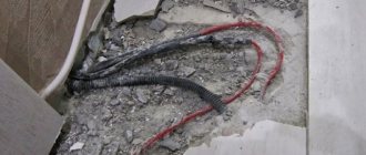
Installation of a heated floor system begins with preparing the surface for installation of a heated floor. The surface must be level, unevenness in area should not exceed ±5 mm. Irregularities and protrusions of no more than 10 mm are allowed. If necessary, the surface is leveled with an additional screed. Failure to comply with this requirement may lead to air-filling of the pipes. If there is high humidity in the room below, it is advisable to install waterproofing (polyethylene film).
After leveling the surface, it is necessary to lay a damper tape at least 5 mm wide along the side walls to compensate for the thermal expansion of the heated floor monolith. It must be laid along all walls framing the room, racks, door frames, bends, etc. The tape should protrude above the planned height of the floor structure by at least 20 mm.
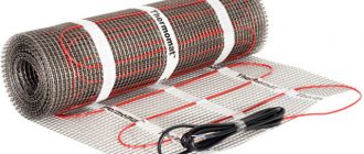
After which a layer of thermal insulation is laid to prevent heat leakage into the lower rooms. It is recommended to use foam materials (polystyrene, polyethylene, etc.) with a density of at least 25 kg/m3 as thermal insulation. If it is impossible to lay thick layers of thermal insulation, then in this case foil thermal insulation materials with a thickness of 5 or 10 mm are used. It is important that foil thermal insulation materials have a protective film on the aluminum. Otherwise, the alkaline environment of the concrete screed destroys the foil layer within 3–5 weeks.
Pipe layout
It is carried out with a certain step and in the required configuration. It is recommended that the supply pipeline should be laid closer to the outer walls.
When laying a “single coil” (Fig. 2), the temperature distribution of the floor surface is not uniform.
Fig.2 Laying underfloor heating loops with a single coil
When laying spirally (Fig. 3), pipes with opposite flow directions alternate, with the hottest section of the pipe adjacent to the coldest. This leads to an even temperature distribution over the floor surface.
Fig.3 Laying heated floor loops in a spiral.
The pipe is laid according to the markings applied to the heat insulator, with anchor brackets every 0.3 - 0.5 m, or between special protrusions of the heat insulator. The laying step is calculated and ranges from 10 to 30 cm, but should not exceed 30 cm, otherwise uneven heating of the floor surface will occur with the appearance of warm and cold stripes. Areas near the exterior walls of a building are called boundary zones. Here it is recommended to reduce the pipe laying pitch in order to compensate for heat loss through the walls. The length of one circuit (loop) of a heated floor should not exceed 100–120 m, the pressure loss per loop (including fittings) should not exceed 20 kPa; the minimum speed of water movement is 0.2 m/s (to avoid the formation of air pockets in the system).
After laying out the loops, immediately before pouring the screed, the system is pressure tested at a pressure of 1.5 of the working pressure, but not less than 0.3 MPa.
When pouring a cement-sand screed, the pipe should be under a water pressure of 0.3 MPa at room temperature. The minimum pouring height above the pipe surface must be at least 3 cm (the maximum recommended height, according to European standards, is 7 cm). The cement-sand mixture must be at least grade 400 with a plasticizer. After pouring, it is recommended to “vibrate” the screed. When the length of a monolithic slab is more than 8 m or the area is more than 40 m2, it is necessary to provide seams between the slabs with a minimum thickness of 5 mm to compensate for the thermal expansion of the monolith. When pipes pass through seams, they must have a protective sheath of at least 1 m in length.
The system is started only after the concrete has completely dried (approximately 4 days per 1 cm of screed thickness). The water temperature when starting the system should be room temperature. After starting the system, increase the supply water temperature daily by 5°C to operating temperature.
The nuances of choosing the optimal step
The degree of efficiency and cost of the entire circuit depends on the correct choice of the pitch between the laid heated floor pipes.
However, its calculation depends on many factors. The standard distance between contours is 100-200 mm.
Variable or constant pitch is also possible:
- If the heating load is less than 50 W per 1 m2, the circuit pitch will be constant and equal to 200 mm.
- With an increased heating load of 80 W per 1 m2 or more, the distance will be 150 mm.
- In other cases, it is necessary to use a variable step. For example, along the perimeter of one or two external walls, the water circuit will be laid in a smallest increment of 100 mm. Moving to the center of the room, the gaps will gradually increase to 200 mm.
In practice, if you plan to heat underfloor heating economically, a step of 150 mm is used. This indicator is optimal in almost any conditions.
If the heat loss of a building exceeds the heat transfer, it is worth thinking about its effective insulation - in this case, reducing the pitch will not solve the problem.
A detailed algorithm for calculating pipes for heated floors is described in this article.
Basic temperature requirements for underfloor heating systems
- It is recommended to take the average temperature of the floor surface no higher (according to SNiP 41-01-2003, clause 6.5.12):
- 26°C for rooms with constant occupancy
- 31°C for rooms with temporary occupancy and bypass paths of swimming pools
- The temperature of the floor surface along the axis of the heating element in children's institutions, residential buildings and swimming pools should not exceed 35°C
According to SP 41-102-98, the temperature difference in certain areas of the floor should not exceed 10°C (optimally 5°C). The coolant temperature in the underfloor heating system should not exceed 55°C (SP 41-102-98 clause 3.5 a).
Installation in an apartment
Probably, many residents have had the idea to independently connect water heated floors “for free” to a central heating or hot water system. And some even do this, but in most cases it is prohibited by local law.
For example, in Moscow there is government decree No. 73-PP dated February 8, 2005; Appendix No. 2 clearly states that it is prohibited to re-equip public water supply systems for floor heating.
If you break the rules, at best, you can get a fine on your first visit to the plumbers. And at worst, there is a risk of leaving your neighbors without heating.
In some regions the ban does not apply, but connection requires an examination so as not to disrupt the operation of the system.
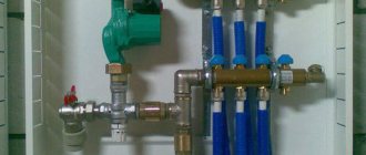
In general, from a technical point of view, such options are possible, but only if a separate pumping and mixing unit is connected and the pressure in the system is maintained at the outlet.
Note! If there is a jet pump (elevator) in an apartment building, then metal-plastic and polypropylene pipes cannot be used.
Set of water heated floors for 15 m2
Heated floor kit for heating rooms with an area of 15-20 m2 with a mixing unit with manual adjustment of the coolant temperature based on the mixing and separating valve MIX 03. The operating temperature of the coolant is adjusted manually by turning the valve handle.
When laying a heated floor loop in a spiral (screed thickness 3 cm with ceramic tile flooring) in increments of 15-20 cm and an estimated coolant temperature of 30°C - floor surface temperature 24-26°C, coolant flow rate of about 0.2 m3/h , flow speed 0.2-0.5 m/s, pressure loss in the loop approximately 5 kPa (0.5 m).
Accurate calculations of thermal and hydraulic parameters can be carried out using the free underfloor heating calculation program Valtec Prog.
| Name | vendor code | Qty. | Price |
| MP pipe Valtec | V1620 | 100 m | 3 580 |
| Plasticizer | THZ.P.10 | 2x10 l | 1 611 |
| Damper tape | THZ.LD.100.01.25 | 2x10 m | 1 316 |
| Thermal insulation | VT.HS.FP.0312 | 18 m2 | 2 648 |
| Three way mixing valve | VT.MIX03.G.05 ¾” | 1 | 1 400 |
| Circulation pump | UPC 25-40 | 1 | 2 715 |
| Nipple adapter | VT 580 1”x3/4” | 1 | 56.6 |
| Nipple adapter | VT 580 1”x1/2” | 1 | 56.6 |
| Ball valve | VT 218 ½” | 1 | 93.4 |
| Straight connector with transition to internal thread | VTm 302 16x ½” | 2 | 135.4 |
| Ball valve | VT 219 ½” | 1 | 93.4 |
| Tee | VT 130 ½” | 1 | 63.0 |
| Barrel | VT 652 ½”x60 | 1 | 63.0 |
| H-B adapter | VT 581 ¾”x ½” | 1 | 30.1 |
| Total | 13 861.5 |
Advantages and disadvantages
The advantages of water heated floors are fully revealed only when using cheap energy sources, such as gas, coal, firewood. Heating the coolant with an electric boiler is approximately 7 times more expensive than using gas equipment.
The gigantic heat capacity of the water heated floor system is another plus. A room containing ≈ 100 kg/m2 of heated concrete cannot cool down quickly (only the top layer of screed is taken into account).
But there are also disadvantages. First of all, this is monstrous inertia. It takes time and energy to warm up such a layer of screed.
Inertia leads to the fact that temperature control of a water heated floor is very conditional. Control equipment takes temperature readings from the coolant, floor surface and air (in some thermostats). But the changes made through the thermostat appear very slowly.
Set of water heated floors up to 30 m2 - 1
Heated floor kit for heating rooms with an area of 30-40 m2 with a mixing unit with manual adjustment of the coolant temperature based on the mixing and separating valve MIX 03. The operating temperature of the coolant is adjusted manually by turning the valve handle. To ensure equal coolant flow in the heated floor loops, their length and laying pattern must be the same.
When laying a heated floor loop in a spiral (screed thickness 3 cm with ceramic tile flooring) in increments of 15-20 cm and an estimated coolant temperature of 30°C - floor surface temperature 24-26°C, coolant flow rate of about 0.2 m3/h , flow speed 0.2-0.5 m/s, pressure loss in the loop approximately 5 kPa (0.5 m).
Accurate calculations of thermal and hydraulic parameters can be carried out using the free underfloor heating calculation program Valtec Prog.
| Name | vendor code | Qty. | Price |
| MP pipe Valtec | V1620 | 200 m | 7 160 |
| Plasticizer | THZ.P.10 | 4x10 l | 3 222 |
| Damper tape | THZ.LD.100.01.25 | 3x10 m | 1 974 |
| Thermal insulation | VT.HS.FP.0312 | 2x18 m2 | 5 296 |
| Three way mixing valve | VT.MIX03.G.05 ¾” | 1 | 1 400 |
| Nipple adapter | VT 580 1”x3/4” | 2 | 113.2 |
| Nipple | VT 582 3/4” | 1 | 30.8 |
| Tee | VT 130 ¾” | 1 | 96.7 |
| Square | VT 93 ¾” | 1 | 104.9 |
| Direct drive | VT 341 ¾” | 1 | 104.9 |
| Circulation pump | UPC 25-40 | 1 | 2 715 |
| Ball valve | VT 217 ¾” | 2 | 266.4 |
| Collector | VT 500n 2 outlets x ¾” x ½” | 2 | 320 |
| Cork | VT 583 ¾” | 2 | 61.6 |
| Fitting for MP pipe | VT 710 16(2.0) | 4 | 247.6 |
| Fitting for MP pipe | VTm 301 20 x ¾” | 1 | 92.4 |
| Fitting for MP pipe | VTm 302 20 x ¾” | 1 | 101.0 |
| Total | 23 306.5 |
Set of water heated floors up to 30 m2 - 2
Heated floor kit for heating rooms with an area of 30-40 m2 with a mixing unit with manual adjustment of the coolant temperature based on the mixing and separating valve MIX 03. The operating temperature of the coolant is adjusted manually by turning the valve handle. To facilitate air release, the system is supplemented with automatic air vents and drain valves. To ensure equal coolant flow in the heated floor loops, their length and laying pattern must be the same. Reinforced thermal insulation allows you to install a heated floor system over unheated rooms.
When laying a heated floor loop in a spiral (screed thickness 3 cm with ceramic tile flooring) in increments of 15-20 cm and an estimated coolant temperature of 30°C - floor surface temperature 24-26°C, coolant flow rate of about 0.2 m3/h , flow speed 0.2-0.5 m/s, pressure loss in the loop approximately 5 kPa (0.5 m).
Accurate calculations of thermal and hydraulic parameters can be carried out using the free underfloor heating calculation program Valtec Prog.
| Name | vendor code | Qty. | Price |
| MP pipe Valtec | V1620 | 200 m | 7 160 |
| Plasticizer | THZ.P.10 | 4x10 l | 3 222 |
| Damper tape | THZ.LD.100.01.25 | 3x10 m | 1 974 |
| Thermal insulation | VT.HS.FP.0312 | 6x5 m2 | 8 562 |
| Three way mixing valve | VT.MIX03.G.05 ¾” | 1 | 1 400 |
| Nipple adapter | VT 580 1”x3/4” | 2 | 113.2 |
| Nipple | VT 582 3/4” | 1 | 30.8 |
| Tee | VT 130 ¾” | 1 | 96.7 |
| Square | VT 93 ¾” | 1 | 104.9 |
| Direct drive | VT 341 ¾” | 1 | 104.9 |
| Circulation pump | UPC 25-40 | 1 | 2 715 |
| Ball valve | VT 217 ¾” | 2 | 266.4 |
| Collector | VT 500n 2 outlets x ¾” x ½” | 2 | 320 |
| Fitting for MP pipe | VT 710 16(2.0) | 4 | 247.6 |
| Fitting for MP pipe | VTm 302 20 x ¾” | 1 | 101 |
| Fitting for MP pipe | VTm 301 20 x ¾” | 1 | 92.4 |
| Manifold tee for mounting an air vent and drain valve | VT 530 3/4”x 1/2”x3/8” | 2 | 238.4 |
| Shut-off valve | VT 539 3/8" | 2 | 97.4 |
| Adapter V-N | VT 592 1/2”x3/8” | 2 | 49.4 |
| Automatic air vent | VT 502 1/2” | 2 | 320.8 |
| Drain tap | VT 430 1/2” | 2 | 209.8 |
| Total | 27 446.7 |
Set of water heated floors up to 60 m2 - 1
Heated floor kit for heating rooms with an area of 60-80 m2 with a mixing unit with manual adjustment of the coolant temperature based on the mixing and separating valve MIX 03. The operating temperature of the coolant is adjusted manually by turning the valve handle. To facilitate air release, the system is supplemented with automatic air vents and drain valves. To ensure equal coolant flow in the underfloor heating loops (hydraulic balancing of the loops), manifolds with integrated shut-off and control valves are used. Reinforced thermal insulation allows you to install a heated floor system over unheated rooms.
When laying a heated floor loop in a spiral (screed thickness 3 cm with ceramic tile flooring) in increments of 15-20 cm and an estimated coolant temperature of 30°C - floor surface temperature 24-26°C, coolant flow rate of about 0.2 m3/h , flow speed 0.2-0.5 m/s, pressure loss in the loop approximately 5 kPa (0.5 m).
Accurate calculations of thermal and hydraulic parameters can be carried out using the free underfloor heating calculation program Valtec Prog.
| Name | vendor code | Qty. | Price |
| MP pipe Valtec | V1620 | 400 m | 14 320 |
| Plasticizer | THZ.P.10 | 8x10 l | 6 444 |
| Damper tape | THZ.LD.100.01.25 | 6x10 m | 3 948 |
| Thermal insulation | VT.HS.FP.0312 | 12x5 m2 | 17 124 |
| Three way mixing valve | VT.MIX03.G.05 ¾” | 1 | 1 400 |
| Nipple adapter | VT 580 1”x3/4” | 2 | 113.2 |
| Nipple | VT 582 3/4” | 1 | 30.8 |
| Tee | VT 130 ¾” | 1 | 96.7 |
| Square | VT 93 ¾” | 1 | 104.9 |
| Direct drive | VT 341 ¾” | 1 | 104.9 |
| Circulation pump | UPC 25-40 | 1 | 2 715 |
| Ball valve | VT 217 ¾” | 2 | 266.4 |
| Collector | VT 560n 4 outlets x ¾” x ½” | 1 | 632.9 |
| Collector | VT 580n 2 outlets x ¾” x ½” | 2 | 741.8 |
| Fitting for MP pipe | VT 710 16(2.0) | 8 | 495.2 |
| Fitting for MP pipe | VTm 302 20 x ¾” | 1 | 101 |
| Fitting for MP pipe | VTm 301 20 x ¾” | 1 | 92.4 |
| Manifold tee for mounting an air vent and drain valve | VT 530 3/4”x 1/2”x3/8” | 2 | 238.4 |
| Shut-off valve | VT 539 3/8" | 2 | 97.4 |
| Adapter V-N | VT 592 1/2”x3/8” | 2 | 49.4 |
| Automatic air vent | VT 502 1/2” | 2 | 320.8 |
| Drain tap | VT 430 1/2” | 2 | 209.8 |
| Bracket for manifold | VT 130 3/4” | 2 | 266.4 |
| Total |
Set of water heated floors up to 60 m2 - 2. (automatic temperature control)
Heated floor kit for heating rooms with an area of 60-80 m2 with a mixing unit with manual adjustment of the coolant temperature based on the mixing and separating valve MIX 03. The operating temperature of the coolant is adjusted automatically by the servo drive of the valve, depending on the value of the coolant temperature set on the scale of the overhead thermostat. To facilitate air release, the system is supplemented with automatic air vents and drain valves. To ensure equal coolant flow in the underfloor heating loops (hydraulic balancing of the loops), manifolds with integrated shut-off and control valves are used. Reinforced thermal insulation allows you to install a heated floor system over unheated rooms.
When laying a heated floor loop in a spiral (screed thickness 3 cm with ceramic tile flooring) in increments of 15-20 cm and an estimated coolant temperature of 30°C - floor surface temperature 24-26°C, coolant flow rate of about 0.2 m3/h , flow speed 0.2-0.5 m/s, pressure loss in the loop approximately 5 kPa (0.5 m).
Accurate calculations of thermal and hydraulic parameters can be carried out using the free underfloor heating calculation program Valtec Prog.
| Name | vendor code | Qty. | Price |
| MP pipe Valtec | V1620 | 400 m | 14 320 |
| Plasticizer | THZ.P.10 | 8x10 l | 6 444 |
| Damper tape | THZ.LD.100.01.25 | 6x10 m | 3 948 |
| Thermal insulation | VT.HS.FP.0312 | 12x5 m2 | 17 124 |
| Three way mixing valve | VT.MIX03.G.05 ¾” | 1 | 1 400 |
| Nipple adapter | VT 580 1”x3/4” | 2 | 113.2 |
| Nipple | VT 582 3/4” | 1 | 30.8 |
| Tee | VT 130 ¾” | 1 | 96.7 |
| Square | VT 93 ¾” | 1 | 104.9 |
| Direct drive | VT 341 ¾” | 1 | 104.9 |
| Circulation pump | UPC 25-40 | 1 | 2 715 |
| Ball valve | VT 217 ¾” | 2 | 266.4 |
| Collector | VT 560n 4 outlets x ¾” x ½” | 1 | 632.9 |
| Collector | VT 580n 2 outlets x ¾” x ½” | 2 | 741.8 |
| Fitting for MP pipe | VT 710 16(2.0) | 8 | 495.2 |
| Fitting for MP pipe | VTm 302 20 x ¾” | 1 | 101 |
| Fitting for MP pipe | VTm 301 20 x ¾” | 1 | 92.4 |
| Manifold tee for mounting an air vent and drain valve | VT 530 3/4”x 1/2”x3/8” | 2 | 238.4 |
| Shut-off valve | VT 539 3/8" | 2 | 97.4 |
| Adapter V-N | VT 592 1/2”x3/8” | 2 | 49.4 |
| Automatic air vent | VT 502 1/2” | 2 | 320.8 |
| Drain tap | VT 430 1/2” | 2 | 209.8 |
| Servomotor for mixing valve | NR 230 | 1 | 3 919 |
| Control surface thermostat | EM 548 | 1 | 550.3 |
| Bracket for manifold | VT 130 3/4” | 2 | 266.4 |
| Total |
Set of water heated floors up to 60 m2 - 3. (automatic temperature control)
Heated floor kit for heating rooms with an area of 60-80 m2 with a mixing unit with manual adjustment of the coolant temperature based on the mixing and separating valve MIX 03. The operating temperature of the coolant is adjusted automatically by the servo drive of the valve, depending on the value of the coolant temperature set on the scale of the overhead thermostat. The system uses a manifold block with control valves with flow meters (optional) to ensure equal coolant flow in the underfloor heating loops (hydraulic balancing of the loops). The use of a manifold adjustable bypass allows you to redirect the coolant flow from the supply to the return manifold in the case when the flow through the manifold loops decreases below the value set on the bypass bypass valve. This allows the hydraulic characteristics of the manifold system to be maintained regardless of the influence of the manifold loop controls (manual, thermostatic valves or servos).
When laying a heated floor loop in a spiral (screed thickness 3 cm with ceramic tile flooring) in increments of 15-20 cm and an estimated coolant temperature of 30°C - floor surface temperature 24-26°C, coolant flow rate of about 0.2 m3/h , flow speed 0.2-0.5 m/s, pressure loss in the loop approximately 5 kPa (0.5 m).
Accurate calculations of thermal and hydraulic parameters can be carried out using the free underfloor heating calculation program Valtec Prog.
| Name | vendor code | Qty. | Price |
| MP pipe Valtec | V1620 | 400 m | 14 320 |
| Plasticizer | THZ.P.10 | 8x10 l | 6 444 |
| Damper tape | THZ.LD.100.01.25 | 6x10 m | 3 948 |
| Thermal insulation | VT.HS.FP.0312 | 12x5 m2 | 17 124 |
| Three way mixing valve | VT.MIX03.G.05 ¾” | 1 | 1 400 |
| Straight line V-N | VT 341 1” | 1 | 189.4 |
| Circulation pump | UPC 25-40 | 1 | 2 715 |
| Ball valve | VT 219 1” | 3 | 733.5 |
| Collector block 1** | VT 594 MNX 4x 1” | 1 | 4 036.1 |
| Collector block 2** | VT 595 MNX 4x 1” | 1 | 5 714.8 |
| Dead-end bypass * | VT 666 | 1 | 884.6 |
| Fitting for MP pipe Eurocone | VT TA 4420 16(2.0)x¾” | 8 | 549.6 |
| Tee | VT 130 1” | 1 | 177.2 |
| Servomotor for mixing valve | NR 230 | 1 | 3 919 |
| Control surface thermostat | EM 548 | 1 | 550.3 |
| Total 1 | 56 990.7 | ||
| Total 2 | 58 669.4 |
* - option
** - optional
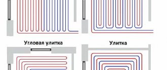
Water circuit installation diagrams
Schematically, laying pipes for arranging a liquid circuit can be done in one of the following ways:
- coil;
- double coil;
- snail.
Coil . The method of laying such a contour is the simplest and is performed in loops. This option will be optimal for a room divided into zones with different purposes, for which it will be convenient to use different temperature conditions.
The first loop is installed around the perimeter of the room, then a single snake is inserted inside. Thus, a maximally heated coolant will circulate in one half of the room, while a cooled one will circulate in the other, and accordingly the temperature will be different.
The coil turns can be spaced evenly, but the bends of the water circuits in this case will have strong creases.
The serpentine pipe placement method is ideal for rooms with little heat loss. They are used not only for apartments and private houses, but also for industrial facilities where there is a need to heat all year round
Double coil . In this case, the supply and return circuits are located next to each other throughout the room.
Angle coil . It is used exclusively for corner rooms where there are two external walls.
The advantages of the serpentine shape include simple planning and installation. Disadvantages: temperature changes in one room, pipe bends are quite sharp, so you cannot use a small pitch - this can cause a pipe break.
When laying the contour in the edge zones of the room (floor areas where external walls, windows, doors are located), the pitch should be smaller in comparison with other turns - 100-150 mm
Snail . Using this arrangement, supply and return pipes are installed throughout the room. They are placed parallel to each other and installed starting from the perimeter of the walls and moving to the center of the room.
The supply line in the middle of the room ends in a loop. Next, parallel to it, a return line is installed, which is laid from the center of the room and along its perimeter, moving towards the collector.
The presence of an external wall in the room may require double laying of pipes along it.
Due to the alternation of two lines when laying using the snail method, temperature fluctuations in the supply and return lines can be up to 10 °C
The advantages of this method include: uniform heating of the room; due to smooth bends, the system has little hydraulic resistance, and savings in consumables can reach 15% compared to the serpentine method. However, there are also disadvantages - complex design and installation.