Despite the fact that many devices operate on direct current, the country's entire energy system is built on alternating current.
The latter has a number of advantages: ease of transformation, low cost of generators and engines. How does alternating current occur?
AC Features
Alternating current has different properties from direct current. They are clearly manifested when an inductance or capacitance is included in the circle.
If you include a coil with a movable iron core in a DC circle, and an incandescent lamp as an indicator, you can see that changing the inductance (introducing an iron core into the coil) does not affect the current strength.
If inductance is present in an alternating current circuit, then with an increase in inductance (gradual introduction of an iron core into the coil), the current decreases. Inductance in an AC circuit creates a certain resistance (but without generating heat), it is called reactance .
If you include a battery of variable capacitors in a DC circuit, then no current will flow at any capacitance (the capacitor breaks the circuit).
If a capacitance is included in an alternating current circuit, then the current exists, and the larger the capacitance is included in the circle, the greater the current. Capacitance in an AC circuit creates a certain reactance that is inversely proportional to the capacitance.
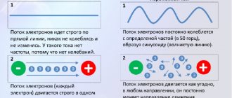
Charged particles that form a constant current move, albeit slowly, but all the time in the same direction with a constant speed. In alternating current, the direction of movement of charged particles changes in accordance with changes in the emf.
Technical alternating current (f = 50 Hz) is called quasi-stationary , since the length of its electromagnetic wave λ\lambda λ = c Т сТ сТ = 6 x 10³ km is very large compared to the length of the circle conductors. In this case, the current strength at any time is almost the same in all sections of the circuit. Kirchhoff's laws can be applied to quasi-stationary current.
The advantages of alternating current over direct current are that it can be easily transformed from one voltage to another, and it is also easier to generate than direct current.
Methods of obtaining
Today there are quite a large number of methods for producing alternating current. Therefore, in this article we will consider the most interesting ones from a practical point of view.
Frame with magnets
To do this, you will need a frame made of any metal, the ends of which allow you to organize rotation. Two magnets with opposite poles are installed at opposite ends with respect to the frame. It should be noted that the magnitude of the alternating current will depend on the resistance of the wires, so it is better to take a product with a large cross-section and high conductivity. When the circuit rotates, an EMF will be induced in its electrical network, which will lead to the flow of alternating current.
Rice. 1. Frame and magnets
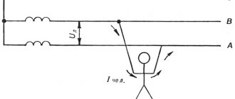
As you can see in the figure above, with a uniform maximum distance between the sides of the metal ring and the poles of the magnet, the magnitude of the electromotive force is zero, the magnetic lines do not intersect the conductor. The sine wave of voltage and current originates from the zero mark. Then the frame moves and the EMF changes until it reaches its maximum when the sides optimally approach the magnets. As the frame rotates further, its sides will again move away from the magnets and the alternating emf will again drop to zero.
When the position changes, the direction of flow of alternating current also changes, which is displayed on the graph as a transition of the curve to the negative plane of the graph. Of course, such a scheme is not suitable for industrial generators, so they use an improved principle.
Asynchronous and synchronous generator
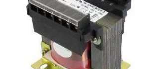
An asynchronous electric machine is similar in design to the design of a transformer. It is used for the generation and transmission of alternating current electricity in three-phase networks. Typically, an electric machine can be used as both a three-phase motor and a generator, many of which are reversible.
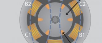
In its design, it resembles a frame, but in a three-phase design - for each of the phases, its own coil is placed in the stator, replacing one turn of the ring. All phase windings are shifted relative to each other by 120° in the geometric plane.
Rice. 2. Asynchronous generator device
Due to the physical displacement of the windings, alternating current is induced into them with that delay, in relation to the previous phase, which requires the rotor to overcome the corresponding distance. Due to this, the voltage and current in each phase are shifted relative to each other. The rotation frequency determines the speed at which a sinusoid crosses the x-axis per unit time. In domestic networks, the industrial frequency of alternating current is 50Hz.
Rice. 3. Voltage in three-phase network
However, as alternating current generators, asynchronous machines have a number of disadvantages:
- high starting currents;
- the lag of the electromotive force from the magnetic field that induces it;
- less control over the system.
Therefore, a synchronous type generator circuit is now quite often used. Structurally, it is similar to the previous model, with the difference that it has an additional coil connected through a sliding contact. It significantly reduces inrush currents and makes work easier.
Rice. 4. Synchronous generator circuit
Inverter
Due to the development of technology, alternating current in the modern world can easily be obtained not only from three-phase generators. An important role is played by solar power plants, which produce direct current, which is rarely used in everyday life and directly in production. To convert the finished direct current into alternating current, special devices are used - inverters.
Rice. 5. Inverter circuit
Figure 5 above shows an example of a simple inverter for producing alternating current. As you can see, constant voltage from the battery is supplied to a pair of transistors VT1 and VT2. Due to differences in the opening speed, one of the transistors will open earlier and all the current will flow through it until a certain prototype of the half-cycle is obtained. Of course, such an alternating current curve will be far from an ideal sinusoid, but it will be more than enough to increase the voltage on the transformer Tr to 220V.
This is the simplest option for converting DC to AC voltage; it may not produce the same frequency as induction generators and is considered by us only as an example. More complex models are produced for home and industrial use.
Vectors
In alternating current technology, periodic changes in e. d.s. (currents) are often depicted as vectors, that is, straight segments of a certain length and a certain direction.
To determine instantaneous values, the vector must have a length corresponding to the maximum value of e. d.s. Its initial phase coincides with the direction of the horizontal axis. Then the vector is rotated counterclockwise and projected onto a fixed vertical axis. The lengths of the projections determine the instantaneous values of e. d.s. for each rotation angle, as illustrated in Figure 9. In Figure 9, changes in e. d.s. presented as a sinusoid on which instantaneous e values are marked. d.s. through every eighth of the period, and by projections of the vector onto the axis for the same fractions of the period.
Figure 9. Determination of instantaneous values of e. d.s. when rotating the vector
Converter circuits
Inverters are classified according to their operating principle, shape and design.
Operating principle
Based on this feature, devices are divided into two types: autonomous and grid-driven inverters.
Autonomous ones are divided into several subgroups that combine inverters:
- voltage (IN): installed in most UPSs;
- current;
- resonant.
Inverters driven by the network are otherwise called dependent. They are used, for example, as power converters on electric locomotives.
Scheme
There are several basic inverter schemes:
- bridge IN without transformer a. It is used in UPSs with a power of over 500 VA and in various devices designed for 220 or 380 V;
- IN with zero terminal transformer a. Used in UPS with a power of 250-500 VA, in 12 or 24 V installations and mobile radio transmitters;
- bridge IN with transformer . Used in UPS of critical facilities with power consumption from several kVA to tens.
Schematic diagram of the converter
Form
According to the form of output voltage, inverters are divided into:
- IN with square wave output signal . In order to ensure the required proportionality of Uout. the control circuit varies the relative duration of the pulses with the keys or phase shifts the control signals of antiphase groups of keys (depending on the design features of the switching module);
- IN with stepped output voltage . The input signal is processed in two stages: by high-frequency conversion, a unipolar step signal is formed, close to a sinusoid with a period halved, and with the help of a bridge converter it is converted into a multipolar one with the required period;
- IN with sinusoidal output voltage . The input DC current is also processed in 2 stages: by high-frequency conversion, a DC voltage is generated, almost equal to the amplitude of the required AC voltage, and then by a bridge inverter, operating on the principle of multiple pulse width modulation.
The resulting direct voltage is converted into a nearly sinusoidal alternating voltage.
Sine wave
The curve in Figure 2 - a sinusoid shows that e. d.s. changes continuously, and the number of its instantaneous values during the period is unlimited: there are as many of them as points that can fit on a sinusoid. During the period, instantaneous identical values of e. d.s. There are two signs of the same sign. Over the period e. d.s. 2 times it reaches the largest (maximum, amplitude) values, but once it is a positive value, the other time it is a negative value. In a word, from a sinusoid you can get the most complete picture of changes in sinusoidal e. d.s. (current) over time.
Video 2. Sine wave
How to choose an inverter
To select a suitable inverter, you need to pay attention to the following:
- The power of the device must exceed that which its consumers have.
- It is necessary that the characteristics of alternating current (frequency, amplitude, pulse shape) are suitable for the electrical appliances using it.
- When converting, the phase of the sinusoid is of no small importance. The inverter must provide power even when the consumption of connected devices reaches its maximum. This is especially true when it comes to electric motors, pumps or compressors.
To calculate the required inverter power, the following steps must be taken:
- It is necessary to determine their rated power from the technical documentation of the connected devices. Examples include a refrigerator (200 W) and a vacuum cleaner (1000 W). The total power will be 200 + 1000 = 1200 W.
- The peak power value needs to be determined. To do this, the resulting value must be multiplied by 1.3. In the example under consideration, it turns out 1200 × 1.3 = 1560 W.
- Additionally, you should take into account the coefficient, which is equal to 0.6–0.99. For calculations, use the minimum value: 1560/0.6 = 2600. The resulting value is expressed in Volt-Amps. It represents the power that the inverter must provide to power the considered case.
The inverter, which provides current conversion, constantly monitors the mains phase and maintains an output voltage value that is slightly higher than the mains value.