Good day to all! In the last article I talked about alternating voltage and its parameters. This article, in fact, is a continuation of the previous one and will address the issues of alternating voltage and current circuits, as well as their impact on resistance, capacitance and inductance in various combinations. Let's start with the simplest circuits with sinusoidal alternating voltage
To assemble a radio-electronic device, you can pre-make a DIY KIT kit using the link.
Circuit resistance at alternating voltage
AC voltage circuits with resistance are the simplest and most common, so let's start with them.
Alternating sinusoidal voltage and current in resistance.
Let's assume that an alternating voltage u resistance R , then, in accordance with Ohm's law, electric current i
where Um is the amplitude value of the alternating voltage,
Im – amplitude value of alternating current,
ω – angular frequency,
t – time,
φ – initial phase
Thus, the effective I and the average value Icp of the alternating current will be determined by the following expressions
Since the voltage and current in a circuit with resistance have the same initial phase, that is, the phases coincide and the achievement of the amplitude values of the voltage Um and current Im occurs simultaneously.
The expression “phase coincidence” is associated with the concept of phase shift ψ , which determines the difference in the initial phases of two sinusoids of the same frequency. Consequently, the phase shift between voltage and current with active resistance will be zero
where φu is the initial voltage phase,
φi is the initial phase of the current.
To assess energy characteristics, the concept of power was introduced; in alternating voltage circuits there are several power characteristics. One of them is instantaneous power Р m , defined as the product of instantaneous voltage and current values
where Um is the amplitude value of the alternating voltage,
Im – amplitude value of alternating current,
U – effective value of alternating voltage,
I – effective value of alternating current.
Thus, the instantaneous power Pm changes at twice the frequency compared to the frequency of voltage and current and ranges from 0 to 2UI.
Another energy characteristic is the average power value over the period P or active power , which is determined by the following expression
where Рm is instantaneous power,
U – effective value of alternating voltage,
I – effective value of alternating current.
Alternating current. Its characteristics
Electric current is the directional movement of charged particles. The quantitative characteristics of the current are its current strength (the ratio of the charge transferred through the cross-section of the conductor per unit time) and its density, determined by the ratio. The unit of current measurement is ampere (1A is the characteristic value of the current consumed by household electric heating appliances). Necessary conditions for the existence of current are the presence of free charge carriers, a closed circuit and an EMF source (battery) that supports directional movement.
Electric current can exist in various environments: in metals, vacuum, gases, in solutions and melts of electrolytes, in plasma, in semiconductors, in the tissues of living organisms. When current flows, charge carriers almost always interact with the environment, accompanied by the transfer of energy to the latter in the form of heat. The role of the EMF source is precisely to compensate for heat losses in the circuits. Electric current in metals is caused by the movement of relatively free electrons through the crystal lattice. The reasons for the existence of free electrons in conducting crystals can only be explained in the language of quantum mechanics.
Experience shows that the strength of the electric current flowing through a conductor is proportional to the potential difference applied to its ends (Ohm's law). The constant proportionality coefficient between current and voltage for a selected conductor is called electrical resistance. Resistance is measured in ohms (the resistance of the human body is about 1000 ohms). The electrical resistance of conductors increases slightly with increasing temperature. This is due to the fact that when heated, the nodes of the crystal lattice enhance chaotic thermal vibrations, which prevents the directional movement of electrons.
In many problems, direct consideration of lattice vibrations turns out to be very labor-intensive. To simplify the interaction of electrons with oscillating units, it turns out to be convenient to replace them with collisions with gas particles of hypothetical particles - phonons, the properties of which are selected so as to obtain a description as close as possible to reality and can turn out to be very exotic. Objects of this type are very popular in physics and are called quasiparticles. In addition to interactions with vibrations of the crystal lattice, the movement of electrons in a crystal can be hampered by dislocations—disturbances in the regularity of the lattice. Interactions with dislocations play a decisive role at low temperatures, when thermal vibrations are practically absent.
Some materials at low temperatures completely lose electrical resistance, turning into a superconducting state. Current in such media can exist without any EMF, since there are no energy losses during collisions of electrons with phonons and dislocations. The creation of materials that maintain a superconducting state at relatively high (room) temperatures and low currents is a very important task, the solution of which would make a real revolution in modern energy, because would make it possible to transmit electricity over long distances without thermal losses.
Currently, electric current in metals is used mainly to convert electrical energy into thermal energy (heaters, light sources) or mechanical energy (electric motors). In the latter case, electric current is used as a source of magnetic fields, the interaction with which of other currents causes the appearance of forces.
Alternating current
As is known, the current strength at any time is proportional to the emf of the current source (Ohm's law for a complete circuit). If the emf of the source does not change over time and the parameters of the circuit remain unchanged, then some time after the circuit is closed, the changes in current strength stop, and direct current flows in the circuit.
However, in modern technology, not only direct current sources are widely used, but also various electric current generators, in which the EMF changes periodically. When an alternating EMF generator is connected to an electrical circuit, forced electromagnetic oscillations or alternating current occur in the circuit.
Alternating current is periodic changes in current and voltage in an electrical circuit that occur under the influence of alternating emf from an external source.
Alternating current is an electric current that changes over time according to a harmonic law.
In the future, we will study forced electrical oscillations that occur in circuits under the influence of a voltage that varies harmoniously with frequency u according to a sinusoidal or cosine law:
where u is the instantaneous voltage value, Um is the voltage amplitude, u is the cyclic frequency of oscillations. If the voltage changes with frequency u, then the current in the circuit will change with the same frequency, but the current fluctuations do not necessarily have to be in phase with the voltage fluctuations.
Therefore, in the general case:
where is the phase difference (shift) between current and voltage fluctuations.
Alternating current ensures the operation of electric motors in machines in plants and factories, powers lighting fixtures in our apartments and outdoors, refrigerators and vacuum cleaners, heating appliances, etc. The frequency of voltage fluctuations in the network is 50 Hz. The alternating current has the same oscillation frequency. This means that within 1 s the current will change its direction 50 times. A frequency of 50 Hz is accepted for industrial current in many countries around the world. In the USA, the frequency of industrial current is 60 Hz.
Resistor in AC circuit
Let the circuit consist of conductors with low inductance and high resistance R (resistors). For example, such a circuit could be the filament of an electric lamp and the supply wires. The value R, which we have hitherto called electrical resistance or simply resistance, will now be called active resistance. There may be other resistances in an AC circuit, depending on the inductance of the circuit and its capacitance. Resistance R is called active because only it releases energy, i.e.
The resistance of an electrical circuit element (resistor), in which electrical energy is converted into internal energy, is called active resistance.
So, there is a resistor in the circuit, the active resistance of which is R, and there is no inductor and capacitor (Fig. 1).
Let the voltage at the ends of the circuit change according to the harmonic law:
As with direct current, the instantaneous value of the current is directly proportional to the instantaneous value of the voltage. Therefore, we can assume that the instantaneous value of the current is determined by Ohm’s law:
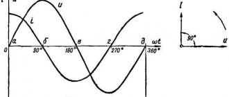
Consequently, in a conductor with active resistance, current fluctuations in phase coincide with voltage fluctuations (Fig. 2), and the current amplitude is equal to the voltage amplitude divided by the resistance:
At low frequencies of alternating current, the active resistance of the conductor does not depend on frequency and practically coincides with its electrical resistance in a direct current circuit.
1.1 Coil in an alternating current circuit
Inductance affects the strength of alternating current in a circuit. This can be discovered by simple experiment. Let's make a circuit of a high-inductance coil and an incandescent lamp (Fig. 3). Using a switch, you can connect this circuit to either a DC voltage source or an AC voltage source. In this case, the direct voltage and the effective value of the alternating voltage must be the same. Experience shows that the lamp glows brighter at constant voltage. Consequently, the effective value of the current in the circuit under consideration is less than the direct current.
This is explained by self-induction. When the coil is connected to a constant voltage source, the current in the circuit increases gradually. The vortex electric field that appears as the current increases slows down the movement of electrons. Only after some time does the current reach its highest (steady) value corresponding to a given constant voltage. If the voltage changes quickly, then the current strength will not have time to reach those steady-state values that it would acquire over time at a constant voltage equal to the maximum value of the alternating voltage. Consequently, the maximum value of the alternating current (its amplitude) is limited by the inductance L of the circuit and will be smaller, the greater the inductance and the greater the frequency of the applied voltage.
Let's prove this mathematically. Let an ideal coil with an electrical resistance of the wire equal to zero be included in an alternating current circuit (Fig. 4).
When the current changes according to the harmonic law:
A self-induced emf occurs in the coil:
where L is the inductance of the coil, u is the cyclic frequency of alternating current.
Since the electrical resistance of the coil is zero, the self-induction EMF in it at any moment of time is equal in magnitude and opposite in sign to the voltage at the ends of the coil created by an external generator:
Consequently, the voltage fluctuations across the inductor lead the current fluctuations at p/2, or, which is the same, the current fluctuations lag in phase behind the voltage fluctuations at p/2.
At the moment when the voltage on the coil reaches its maximum, the current strength is zero (Fig. 5). At the moment when the voltage becomes zero, the current strength is maximum in magnitude.
The product Im ⋅ L ⋅ u is the amplitude of voltage oscillations on the coil:
The ratio of the amplitude of voltage fluctuations on the coil to the amplitude of current fluctuations in it is called inductive reactance (denoted by XL):
The relationship between the amplitude of voltage fluctuations at the ends of the coil and the amplitude of current fluctuations in it coincides in form with the expression of Ohm’s law for a section of a direct current circuit:
Unlike the electrical resistance of a conductor in a DC circuit, inductive reactance is not a constant value that characterizes a given coil. It is directly proportional to the frequency of the alternating current. Therefore, the amplitude of current oscillations in the coil at a constant value of the amplitude of voltage oscillations should decrease in inverse proportion to the frequency. Direct current does not “notice” the inductance of the coil at all. At u = 0, the inductive reactance is zero (XL = 0).
The dependence of the amplitude of current oscillations in the coil on the frequency of the applied voltage can be observed in an experiment with an alternating voltage generator, the frequency of which can be changed. Experience shows that doubling the frequency of alternating voltage leads to a halving of the amplitude of current fluctuations through the coil.
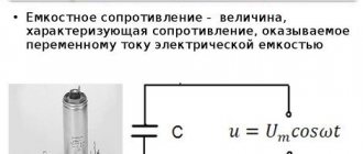
1.2 Capacitor in AC circuit
Let's consider the processes occurring in an alternating current electrical circuit with a capacitor. If you connect a capacitor to a direct current source, a short-term current pulse will appear in the circuit, which will charge the capacitor to the source voltage, and then the current will stop. If a charged capacitor is disconnected from a direct current source and its plates are connected to the terminals of an incandescent lamp, the capacitor will be discharged, and a short-term flash of the lamp will be observed.
When a capacitor is connected to an alternating current circuit, its charging process lasts a quarter of a period. After reaching the amplitude value, the voltage between the plates of the capacitor decreases and the capacitor is discharged within a quarter of the period. In the next quarter of the period, the capacitor is charged again, but the polarity of the voltage on its plates is reversed, etc. The processes of charging and discharging the capacitor alternate with a period equal to the oscillation period of the applied alternating voltage.
As in a DC circuit, electric charges do not pass through the dielectric separating the plates of the capacitor. But as a result of periodically repeating processes of charging and discharging the capacitor, alternating current flows through the wires connected to its terminals. An incandescent lamp connected in series with a capacitor in an alternating current circuit (Fig. 6) appears to be burning continuously, since the human eye, with a high frequency of current fluctuations, does not notice the periodic weakening of the glow of the lamp filament.
Let us establish a connection between the amplitude of voltage fluctuations on the capacitor plates and the amplitude of current fluctuations.
When the voltage changes on the capacitor plates according to the harmonic law:
the charge on its plates changes according to the law:
Electric current in the circuit arises as a result of a change in the charge of the capacitor: i = q'. Therefore, current fluctuations in the circuit occur according to the law:
Consequently, the voltage fluctuations on the capacitor plates in the alternating current circuit lag in phase behind the current fluctuations at p/2, or the current fluctuations lead in phase to the voltage fluctuations at p/2 (Fig. 7). This means that at the moment when the capacitor begins to charge, the current is maximum and the voltage is zero. After the voltage reaches its maximum, the current becomes zero, etc.
The product Um ⋅ м ⋅ C is the amplitude of current oscillations:
The ratio of the amplitude of voltage fluctuations on the capacitor to the amplitude of current fluctuations is called the capacitive reactance of the capacitor (denoted XC):
The relationship between the amplitude value of the current and the amplitude value of the voltage coincides in form with the expression of Ohm's law for a section of a direct current circuit, in which instead of electrical resistance the capacitance of the capacitor appears:
The capacitive reactance of a capacitor, like the inductive reactance of a coil, is not a constant value. It is inversely proportional to the frequency of the alternating current. Therefore, the amplitude of current fluctuations in the capacitor circuit at a constant amplitude of voltage fluctuations on the capacitor increases in direct proportion to the frequency.
1.3 Ohm's law for an alternating current electrical circuit
Let's consider an electrical circuit consisting of a resistor, capacitor and coil connected in series (Fig. 8). If an electric voltage is applied to the terminals of this electrical circuit, varying according to a harmonic law with frequency u and amplitude Um, then forced oscillations of the current will appear in the circuit with the same frequency and a certain amplitude Im. Let us establish a connection between the amplitudes of current and voltage fluctuations
At any moment of time, the sum of the instantaneous voltage values on the series-connected circuit elements is equal to the instantaneous value of the applied voltage:
In all series-connected circuit elements, changes in current strength occur almost simultaneously, since electromagnetic interactions propagate at the speed of light. Therefore, we can assume that fluctuations in current strength in all elements of a series circuit occur according to the law:
The voltage fluctuations across the resistor are in phase with the current fluctuations, the voltage fluctuations across the capacitor are p/2 behind the current fluctuations in phase, and the voltage fluctuations across the coil are ahead of the current fluctuations in phase by p/2.
Therefore, equation (1) can be written as follows:
where URm, UCm and ULm are the amplitudes of voltage fluctuations across the resistor, capacitor and coil.
The amplitude of voltage fluctuations in an alternating current circuit can be expressed through the amplitude values of the voltage on its individual elements using the vector diagram method.
When constructing a vector diagram, it is necessary to take into account that the voltage fluctuations on the resistor coincide in phase with the current fluctuations, therefore the vector depicting the voltage amplitude URm coincides in direction with the vector depicting the current amplitude Im. Voltage fluctuations on the capacitor lag in phase by p/2 from current fluctuations, so the vector
UCm lags behind vector Im by an angle of 90°. Voltage fluctuations on the coil lead current fluctuations in phase by p/2, so the vector ULm leads the vector Im by an angle of 90° (Fig. 9).
In the vector diagram, the instantaneous voltage values on the resistor, capacitor and coil are determined by the projections onto the horizontal axis of the vectors Rm, Cm, Lm rotating at the same angular speed u counterclockwise. The instantaneous voltage value in the entire circuit is equal to the sum of the instantaneous voltages uR, uC, and uL on the individual elements of the circuit, i.e. the sum of the projections of the vectors URm, UCm and ULm onto the horizontal axis. Since the sum of the projections of vectors onto an arbitrary axis is equal to the projection of the sum of these vectors onto the same axis, the amplitude of the total voltage can be found as the modulus of the sum of vectors:
From Figure 9 it can be seen that the voltage amplitude throughout the entire circuit is equal to:
Or
From here
By introducing the symbol for the impedance of an AC circuit:
Let us express the relationship between the amplitude values of current and voltage in an alternating current circuit as follows:
This expression is called Ohm's law for an alternating current circuit.
From the vector diagram shown in Figure 9, it is clear that the phase of the total voltage oscillations is equal to ut + u. Therefore, the instantaneous value of the total voltage is determined by the formula:
The initial phase q can be found from the vector diagram:
The value of cos c plays an important role in calculating power in an alternating current electrical circuit.
1.4 AC power
Power in a DC circuit is determined by the product of voltage and current:
The physical meaning of this formula is simple: since the voltage U is numerically equal to the work of the electric field to move a unit charge, the product U?I characterizes the work to move the charge per unit time flowing through the cross section of the conductor, i.e. is power. The power of the electric current in a given section of the circuit is positive if energy comes to this section from the rest of the network, and negative if energy from this section returns to the network. Over a very short period of time, alternating current can be considered constant.
Therefore, instantaneous power in an alternating current circuit is determined by the same formula:
Let the voltage at the ends of the circuit change according to the harmonic law:
In this case, the power changes over time both in magnitude and sign. During one part of the period, energy flows to a given section of the circuit (p > 0), but during the other part of the period, some portion of the energy returns to the network again (p < 0). As a rule, in all cases we need to know the average power in a section of the circuit over a fairly large period of time, including many periods. To do this, it is enough to determine the average power for one period.
To find the average power over a period, we transform the resulting formula in such a way as to highlight a term in it that does not depend on time. For this purpose, we will use the well-known formula for the product of two cosines:
The expression for instantaneous power consists of two terms. The first does not depend on time, and the second changes sign twice for each period of voltage change: during some part of the period, energy enters the circuit from an alternating voltage source, and during the other part it returns back. Therefore, the average value of the second term over the period is zero.
Consequently, the average power P for a period is equal to the first term, independent of time:
When the phase of current and voltage oscillations coincide (for active resistance R), the average power value is equal to:
In order for the formula for calculating the power of alternating current to coincide in form with a similar formula for direct current (P = IU = I2R), the concepts of effective values of current and voltage are introduced. From the equality of powers we obtain:
The effective current value is a value that is √2 times less than its amplitude value:
The effective value of the current is equal to the strength of such a direct current at which the average power released in a conductor in an alternating current circuit is equal to the power released in the same conductor in a direct current circuit.
Similarly, it can be proven that the effective value of the alternating voltage is √2 times less than its amplitude value:
Note that usually electrical equipment in alternating current circuits shows the effective values of the measured quantities. Turning to the effective values of current and voltage, equation (10) can be rewritten:
Thus, the alternating current power in a section of the circuit is determined precisely by the effective values of current and voltage. It also depends on the phase shift cs between voltage and current. The cos cc multiplier in the formula is called the power factor.
In the case when qc = ± p/2, the energy supplied to a section of the circuit during a period is zero, although there is a current in the circuit. This will be the case, in particular, if the circuit contains only an inductor or only a capacitor. How can the average power be equal to zero in the presence of current in the circuit? This is explained by the graphs shown in Figure 10 of changes over time in instantaneous values of voltage, current and power at cc = – p/2 (purely inductive reactance of the circuit section).
A graph of instantaneous power versus time can be obtained by multiplying the values of current and voltage at each time. From this graph it can be seen that during one quarter of the period the power is positive and energy flows to this section of the circuit; but during the next quarter of the period the power is negative, and this section transfers the previously received energy back into the network without losses. The energy arriving during a quarter of the period is stored in the magnetic field of the current, and then returned to the network without loss.
Only in the presence of a conductor with active resistance in a circuit that does not contain moving conductors, electromagnetic energy is converted into internal energy of the conductor, which heats up. The reverse conversion of internal energy into electromagnetic energy in the area with active resistance no longer occurs.
When designing alternating current circuits, it is necessary to ensure that cos cc is not small. Otherwise, a significant part of the energy will circulate through the wires from the generator to consumers and back. Since the wires have active resistance, energy is spent on heating the wires.
Unfavorable conditions for energy consumption arise when electric motors are connected to the network, since their windings have low active resistance and high inductance. To increase cos cc in the power supply networks of enterprises with a large number of electric motors, special compensating capacitors are included. It is also necessary to ensure that electric motors do not run idle or underload.
This reduces the power factor of the entire circuit. Increasing cos cc is an important national economic task, as it allows for maximum efficiency in using power plant generators and reducing energy losses. This is achieved by proper design of electrical circuits. It is prohibited to use devices with cos cc < 0.85.
Theory
On the one hand, everyone knows that mankind’s first acquaintance with electrical energy occurred through the example of direct current. It was only in 1831 that research into the phenomenon of magnetic induction led to the generation of alternating currents. The first experiments involved an electrical conductor placed in a magnetic flux.
As an example, you should consider an ordinary conductor brought into a closed loop state; the edges of the conductor can be connected to a measuring device to record changes in electrical quantities.
Next you need:
- take a good magnet, if you have a powerful neodymium one on hand, then it will work best;
- connect the conductor to the galvanometer, place the entire electrical circuit on a table or other surface made of insulating material;
- bring the magnet to the conductor as close as possible, preferably the distance is no more than 10 mm;
- make a sharp movement in a perpendicular plane in relation to the conductor;
- pay attention to the device, the galvanometer needle will deviate from the equilibrium position in any direction - as a result of electromagnetic oscillations, an induced emf is induced in the conductor, which causes the appearance of alternating current in a closed circuit.
Repeat the manipulation of the magnet several times, and you will see how the galvanometer uniformly deflects to the side as the pole approaches the conductor and equally uniformly returns to its original position as the magnet moves away. The deviation of the arrow indicates a change in the magnitude of the current and potential induced in the metal. The amplitude of current oscillations is not constant over time, which is why this value is called a variable.
Note that if you move one magnetic pole near the wire, the arrow will deflect in one direction; if you move it with the opposite magnetic pole, then the direction of the arrow deflection will change accordingly.
One circuit is only an example for understanding the essence of producing alternating electric current, since the EMF in it will be too low and the power will not be enough even to power the LED. On an industrial scale, instead of rotating a turn, entire windings with many turns are used. In practice, it does not matter whether the magnet is moving relative to the conductor or whether the closed loop is moving relative to the pole of the magnet.
Therefore, to change the EMF in the generator windings, both the principle of rotation of a rotor made of magnetic material inside the stator windings, and vice versa, the rotor windings inside the magnetic stator can be used.
The magnitude of the electromotive force itself is determined from the relationship of physical parameters using the following formula:
where n is the number of turns of the windings
and the ratio dФB/dt is the rate of change of electromagnetic induction over time.
Ohm's law formula
Ohm's First Law states that the potential difference between two points of a resistor is proportional to the current. Moreover, according to this law, the relationship between potential and current is always constant for ohmic resistors.
V = RI, where:
V—voltage/electric potential (V);
R—electrical resistance (ohm);
I - electric current.
Formula
In it, U is a scalar quantity and is measured in (B). The difference in electrical potential between two points in a circuit indicates the presence of electrical resistance. When I passes through a resistive element R, a drop in electrical potential occurs. This difference occurs due to energy dissipation called the Joule effect. I measures the flow of charges through the body in (A) and is directly proportional to the resistance of the wire.
Ohm's second law states that electrical resistance R is a property of a body that regulates the permeability of I. This property depends on the geometric factors of the body, such as the length or cross-sectional area of the section and on the value R caused. Its amount depends solely on the material of the section.
R= ρ*L/S, where:
R—electrical resistance (Ohm);
ρ—electrical resistivity of the wire (Ohm.m);
L is the length of the conductor (m);
S is the cross-sectional area of the wire (m²).
An ohmic resistor is any body capable of presenting a constant resistance for a given voltage range. The voltage versus current plot for ohmic resistors is linear. A resistor can be considered ohmic in the range in which its potential increases linearly with increasing I.
Resistance can be understood as the slope of the line given by the tangent of the angle. As is known, tangent is defined as the ratio between the opposite and adjacent sides, and, in the case where the resistance is ohmic, can be calculated by the formula: R = U / I.
Triangle
To help remember the formula, you can use a triangle with one side horizontal and the apex at the top, like a pyramid. This is sometimes called Ohm's triangle law. In its upper corner is the letter V, in the left corner is the letter I, and in the lower right corner is R.
Note! To use a triangle, cover the unknown parameter and then calculate it from the other two. If they are on the same line they are multiplied, but if one is above the other they should be separated. In other words, if I needs to be calculated, the voltage is divided by the resistance, that is, V/R.
What is the current in the outlet - direct or alternating?
People who are more or less familiar with electrical engineering can easily answer the question of what current is in the outlet. Of course it's variable. This type of electricity is much easier to produce and transmit over long distances, and therefore the choice in favor of alternating current is obvious.
There are two types of current - direct and alternating. To understand the difference and determine whether the outlet has direct or alternating current, you should delve into some technical features. Alternating current has the property of changing in direction and magnitude. Direct current has stable qualities and direction of movement of charged particles.
Alternating current comes out of the power plant generators with a voltage of 220-440 thousand volts. When approaching an apartment building, the current is reduced to 12 thousand volts, and at the transformer station it is converted to 380 volts.
Advice
The voltage between phases is called linear. The low-voltage section of the step-down substation produces three phases and a zero (neutral) wire. Energy consumers are connected from one of the phases and the neutral wire.
Thus, single-phase alternating current with a voltage of 220 volts enters the building.
The distribution diagram of electricity between houses is presented below:
In the home, electricity is supplied to the meter, and then through automatic machines to the boxes of each room. The boxes contain wiring throughout the room for a couple of circuits - electrical outlets and lighting equipment.
The machines can be provided one for each room or one for each circuit.
Taking into account how many amperes the outlet is designed for, it can be included in a group or connected to a dedicated circuit breaker.
Alternating current accounts for approximately 90% of all electricity consumed. Such a high specific gravity is due to the peculiarities of this type of current - it can be transported over considerable distances by changing the voltage at substations to the required parameters.
Sources of direct current are most often batteries, galvanic cells, solar panels, thermocouples.
Direct current is widely used in local networks of automobile and air transport, in computer electrical circuits, automatic systems, radio and television equipment.
Direct current is used in contact networks of railway transport, as well as on ship installations.
The diagram below shows the fundamental differences between direct and alternating currents.
Home electrical network parameters
The main parameters of electricity are its voltage and frequency. The standard voltage for home electrical networks is 220 volts. The generally accepted frequency is 50 hertz. However, in the USA a different frequency value is used - 60 hertz. The frequency parameter is set by the generating equipment and is unchanged.
It will be interesting➡ PVS wire and cable. Description, decoding and technical application of PVS type wire
The voltage in the network of a particular house or apartment may be different from the nominal value (220 volts). This indicator is influenced by the technical condition of the equipment, network loads, and substation load. As a result, the voltage may deviate from the specified parameter in one direction or another by 20–25 volts.
Current load
All sockets have a certain marking, by which you can judge the permissible current load. For example, the designation "5A" indicates a maximum current of 5 amperes. Acceptable indicators must be observed, since otherwise the equipment may fail, including fire.
The markings on the sockets are shown in the figure below:
All legally sold electrical appliances are accompanied by a passport indicating the power consumption or current load rating.
The largest consumers of electricity are household appliances such as air conditioners, microwave ovens, washing machines, electric stoves and ovens.
For normal operation, such devices will need an outlet with a load of at least 16 amperes.
note
If the documentation for electrical household appliances does not contain information about the consumed amperes (current strength in the outlet), the required values are determined using the electric power formula:
The power indicator is in the passport, the network voltage is known. To determine electricity consumption, you need to divide the power indicator (indicated only in watts) by the voltage value.
Where and when can Ohm's law be applied?
Ohm's law in the form mentioned is valid within fairly wide limits for metals. It is carried out until the metal begins to melt. A less wide range of applications is in solutions (melts) of electrolytes and in highly ionized gases (plasma).
When working with electrical circuits, sometimes you need to determine the voltage drop across a certain element. If it is a resistor with a known resistance value (it is marked on the case), and the current passing through it is also known, you can find out the voltage using Ohm’s formula without connecting a voltmeter.
What is the working principle of alternating current
The English abbreviation AC (Alternating Current) denotes a current that changes its direction and magnitude over time periods. The sinusoid segment “~” is its conventional marking on devices. Applying after this icon and other characteristics is also used.
Below is a figure with the main characteristics of this type of current - nominal frequency and operating voltage.
It should be noted the features of the change in the left graph, made for a single-phase current, in the magnitude and direction of the voltage with the transition to zero over a certain period of time T. For one third of the period, three sinusoids are shifted for a three-phase current on another graph.
O and “b” indicate phases. Any of us has an idea of the presence of 220V in a regular outlet. But for many it will be a discovery that the maximum or otherwise called amplitude value is greater than the acting value by an amount equal to the root of two and is 311 Volts.
Obviously, in the case of direct current, the parameters of direction and voltage remain unchanged, but for alternating current, a transformation of these quantities is observed. In the figure, the opposite direction is the area of the graph below zero.
Let's move on to frequency. This concept means the ratio of periods (full cycles) to a conventional unit of time for a changing current. This indicator is measured in Hertz. The standard European frequency is 50, in the USA the applicable standard is 60G.
This value shows the number of changes in the direction of the current in one second to the opposite and return to the original state.
Alternating current is present when consumer devices are directly connected to electrical panels and sockets. For what reason is there no direct current here? This is done in order to be able to obtain the required voltage in any quantity by using transformers without any significant losses. This technique remains the best way to transmit power on an industrial scale over significant distances with minimal losses.
The rated voltage, which is supplied by powerful generators of power plants, at the output is about 330,000-220,000 Volts. At a substation located in the consumption area, this value is transformed to 10,000V with a transition to a three-phase version of 380 Volts. A separate house is supplied and single-phase voltage reaches your apartment. The voltage between zero and phase will be 220 V, and in the shield between different phases this figure is 380 Volts.
Voltage formula
There is a formula in physics, although it has no practical application. The official formula is written like this.
voltage formula
Where
A is the work done by the electric field to move a charge along a section of the circuit, Joules
q - charge, Coulomb
U—voltage on a section of the electrical circuit, Volts
In practice, the voltage across a section of a circuit is derived through Ohm's law.
It will be interesting➡ Voltage control relay
voltage from Ohm's law
Where
I - current, Amperes
R - resistance, Ohms
Serial and parallel connection of elements
For elements of an electrical circuit (section of a circuit), a characteristic point is a serial or parallel connection. Accordingly, each type of connection is accompanied by a different pattern of current flow and voltage supply. In this regard, Ohm's law is also applied differently, depending on the option of including elements.
Circuit of series-connected resistive elements
In relation to a series connection (a section of a circuit with two components), the following formulation is used:
- I = I1= I2 ;
- U = U1+ U2 ;
- R = R1+ R2
This formulation clearly demonstrates that, regardless of the number of resistive components connected in series, the current flowing through a section of the circuit does not change in value. The magnitude of the voltage applied to the effective resistive components of the circuit is the sum and totals the value of the emf source.
In this case, the voltage on each individual component is equal to: Ux = I * Rx. The total resistance should be considered the sum of the values of all resistive components in the circuit.
Circuit of parallel connected resistive elements
In the case when there is a parallel connection of resistive components, the following formulation is considered fair in relation to the law of the German physicist Ohm:
- I = I1+ I2 … ;
- U = U1= U2 … ;
- 1 / R = 1 / R1+ 1 / R2 + …
Options for creating circuit sections of a “mixed” type, when parallel and serial connections are used, are not excluded. For such options, the calculation is usually carried out by initially calculating the resistive rating of the parallel connection. Then the value of the resistor connected in series is added to the result obtained.
Integral and differential forms of the law
All of the above points with calculations are applicable to conditions when conductors of, so to speak, “homogeneous” structure are used in electrical circuits. Meanwhile, in practice, one often has to deal with the construction of schematics, where the structure of the conductors changes in different sections. For example, wires of a larger cross-section or, conversely, a smaller one, made from different materials, are used.
To take into account such differences, there is a variation of the so-called “differential-integral Ohm’s law.” For an infinitesimal conductor, the current density level is calculated depending on the voltage and conductivity value.
For the differential calculation, the formula is taken: J = ό * E. For the integral calculation, accordingly, the formulation is: I * R = φ1 – φ2 + έ However, these examples are rather closer to the school of higher mathematics and are not actually used in the real practice of a simple electrician.
Current strength
Electric current is the ordered (directed) movement of charged particles. Electric current strength is a quantity ($I$) that characterizes the ordered movement of electric charges and is numerically equal to the amount of charge $∆q$ flowing through a certain surface $S$ (cross section of the conductor) per unit time:
$I={∆q}/{∆t}$
So, to find the current strength $I$, it is necessary to divide the electric charge $∆q$ that passed through the cross section of the conductor during the time $∆t$ by this time. The strength of the current depends on the charge carried by each particle, the speed of their directional movement and the cross-sectional area of the conductor.
Consider a conductor with cross-sectional area $S$. The charge of each particle is $q_0$. The volume of the conductor, limited by sections $1$ and $2$, contains $nS∆l$ particles, where $n$ is the concentration of particles. Their total charge is $q=q_{0}nS∆l$. If the particles move with an average speed $υ$, then during the time $∆t={∆l}/{υ}$ all particles contained in the volume under consideration will pass through the cross section $2$. The current strength is therefore equal to:
$I={∆q}/{∆t}={q_{0}nS∆l·υ}/{∆l}=q_{0}nυS$
In the SI, the unit of current is the basic one and is called the ampere (A) in honor of the French scientist A. M. Ampere (1755-1836). The current strength is measured with an ammeter. The principle of the ammeter is based on the magnetic action of current. An estimate of the speed of ordered movement of electrons in a conductor, carried out using the formula for a copper conductor with a cross-sectional area of $1mm^2$, gives a very insignificant value - $∼0.1$ mm/s.