Types of current
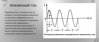
In order to have an idea of what current is in the socket in your home, you should not stop at studying the physical concept of this phenomenon; this data can be obtained from various reference books or from school textbooks. It is enough to confine ourselves to the knowledge that humanity uses two of its types:
- Direct current, the sources of which, as a rule, are batteries, galvanic cells (electric batteries of various types), solar panels, thermocouples. It is widely used in on-board networks of automobile and air transport, electronic circuits of computers, automation systems, radio and television equipment. Contact networks of railways are powered with direct current; it ensures the operation of power plants of a number of ships and vessels.
- Alternating current. More than 90% of all electricity that is generated for the needs of mankind is generated by alternating current generators. Such widespread use is explained by the fact that alternating current, unlike direct current, has the ability to be transmitted over long distances, and transformer substations can change its voltage to the required values, without noticeable losses.
The above property of alternating current answers the question why the main energy supply option was chosen in its favor. At the same time, the importance of direct current cannot be underestimated; it performs other, but no less significant functions, the main one of which is ensuring the operation of electronics.
How many amperes are in a regular battery?
A standard AA battery has a charge of 1.5 volts. This type of battery can produce current up to one and a half (1.5) amperes.
Interesting materials:
How to receive a tax payment? How to get a tax deduction through your personal account? How to get a tax deduction for rent? How to get a password for your personal account at the tax office? How to obtain a tax registration certificate for a legal entity? How to receive a tax notice? How to get an extract from the tax office via the Internet? How to recover tax arrears? How to calculate land tax 2022? How to calculate VAT tax?
Requirements for plug connections
To connect an electrical appliance to the network, a socket and plug are respectively a source and receiver of energy, forming a plug connection. The following requirements apply to it.
- Reliable contact. A weak connection leads to overheating and failure. It is also important to ensure reliable fixation against spontaneous disconnection. Here it is convenient to use spring contacts in the socket.
- Isolation of current-carrying parts from each other.
- Protection against touching live parts with hands or other objects. To protect against children, sockets are provided with special curtains that open only when the plug is inserted.
- Ensuring polarity when connecting. This is important if the connection carries direct current or the device is used in combination with a single-pole switch. The design of the socket does not allow incorrect connection.
- Availability of grounding for devices of protection class 1. It is important to properly connect the grounding in sockets.
Electricity distribution diagram between houses
The low voltage side of the 6000/380 step-down transformer substation produces three phases and a neutral or, as they say, neutral wire. The voltage measured between phases is called linear (Ul), in this case it has a value of 380 V. Individual consumers are connected from one phase and a neutral wire, as a result of which single-phase alternating current with a phase voltage of 220 V enters the house.
Electricity distribution diagram between houses
Home network calculation, power determination
A modern internal power supply system for a house or apartment must satisfy several requirements. She must be:
- Designed for long-term trouble-free operation
- Provided with protection devices against overload, short circuit, electric shock and significant voltage surges
- Provided with various devices to improve the comfort of your stay
- Designed to connect a wide variety of devices
Creating such a system is not an easy task, requiring a thoughtful and systematic approach. It involves the implementation of the following stages: calculation, packaging and installation.
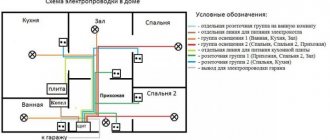
During the calculation process, certain functional areas in the premises are identified that require the connection of any electrical appliances. This work is most conveniently done using a plan of an apartment or house. On the plan you can “arrange” the proposed furniture, “place” chandeliers and lamps, “install” an electric stove, refrigerator, washing machine, etc. This will allow you to determine the location of the sockets, as well as their type. The placement of chandeliers, lamps and lighting will, in turn, allow you to find convenient places for the corresponding switches. On the same plan you should indicate the power of the equipment planned for installation.
Dividing all consumers into groups
Calculation of a home electrical network, as a rule, begins with dividing all consumers into groups. A group means several consumers connected in parallel to one supply wire coming from the distribution board. These are lighting groups, groups of sockets, etc. High-power units (washing machines and electric stoves) are powered by separate lines. A separate group includes kitchen sockets where microwave ovens, electric ovens, dishwashers, electric kettles and much more are connected.
The result of dividing consumers into groups is first best displayed in a table, later supplementing it with new data (Table 1).
Groups of electrical energy consumers with individual protection devices can be formed in three ways:
- By room in the apartment (each room is provided with a separate line)
- By type of consumer: lighting, sockets, electric stoves, washing machines, etc.
- For each consumer, be it a socket or a lamp, there is a separate power supply line with protection devices (European version)
As practice shows, any wiring in a house or apartment is a combination of the above options, depending on specific needs and conditions.
Determination of installed power and load current
An important design stage is to determine the total power consumption of installed equipment in each group.
The amount of installed power allows you to calculate the rated load current on a given circuit. The rated current is the maximum current that will flow through the phase wire. In the internal network of an apartment or house with a voltage of 220 V, it is easily determined by the maximum power consumption.
With a single-phase load, the rated current is In ~ 4.5Pm, where Pm is the maximum power consumption in kilowatts. For example, with Pm = 5 kW In = 4.5 * 5 = 22.5 A.
When distributing consumers into groups, it is necessary to proceed from the following conditions:
- Air conditioning, heated floors, electric stove, washing machine and other powerful consumers with open conductive elements must be connected to separate lines, each of which is protected by a circuit breaker and RCD
- Sockets in areas with high humidity (kitchens and bathrooms) are included in a separate group.
- Living room sockets can be combined into one group
- It is advisable to divide the lighting system of living rooms into two (or more) groups
The division into groups is carried out in a distribution cabinet, where a circuit breaker, and in some cases an RCD, is installed for each group. Thus, each of the groups outside the distribution board represents a separate electrical circuit.
The value of the rated load current allows you to determine both the characteristics of the protective devices and the cross-section of the wire cores.
The simplest is to calculate a group with one appliance, for example an electric oven. Its power consumption is 2 kW (determined from the passport). Rated load current In = 4.5 * 2 = 9 A. Thus, a circuit breaker with a rated current of at least 9 A must be installed in the oven power circuit. The closest rated current is a 10 A circuit breaker.
Calculation of the current load and selection of a circuit breaker for a group with several consumers is complicated by the introduction of a demand coefficient, which determines the probability of simultaneous switching on of all consumers in the group over a long period of time.
Of course, the value of the demand coefficient depends on many objective and subjective factors: the type of apartment, the purpose of electrical devices, etc. For example, the demand coefficient for a TV is usually taken as 1, and the demand coefficient for a vacuum cleaner is 0.1. There are even entire systems for calculating the demand coefficient for both individual apartments and multi-storey buildings.
It is clear that the simultaneous inclusion and operation of all electrical appliances in an apartment or private house is unlikely. Therefore, in our case, the demand coefficient for each group can be determined from a table of average values (Table 2).
To calculate the kitchen outlet group, we assume that the following appliances will be included there:
- Electric kettle - 700 W
- Vegetable cutter - 400 W
- Microwave - 1200 W
- Refrigerator - 300 W
- Freezer - 160 W
- Other - 240 W
The total rated power of these devices in the group is 3000 W.
Taking into account the demand coefficient (equal to 0.7), the rated power will be equal to 3000 * 0.7 = 2100 W.
The rated load current in the circuit of this outlet group will be equal to 4.5 x 2.1 = 9.45 A.
After similar calculations, we will supplement the table. 3 obtained values of power consumption and rated current for the remaining groups.
Selection of core sections and wire type
The cross-section of the wire cores for each group is calculated depending on the expected total power of the devices installed in it and the calculated current values (of course, with some margin). The necessary recommendations can be obtained in the “Rules for the construction of electrical installations” (PUE) - the main document of the electrician.
Table 4 reflects the compliance of load currents and permissible wire cross-sections regulated by the PUE (used for copper wires, because the use of aluminum in electrical wiring of residential premises is currently prohibited).
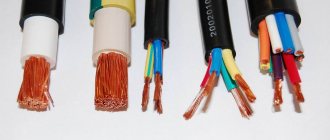
To more accurately calculate the required cross-sections of wire cores, it is necessary not only to be guided by the load power and the material used to make the cores, but also to take into account the method of laying them, length, type of insulation, number of cores in the wire, operating conditions and other factors. Therefore, experienced electricians consider the best option to use cores with a cross section of 1.5 mm2 for the lighting group (4.1 kW and 19 A), 2.5 mm2 for the socket group (5.9 kW and 27 A) and 4-6 mm2 - for high power devices (over 8 kW and 40 A). This option for choosing wire sections is perhaps the most common when installing electrical wiring for apartments and houses. It allows you to increase the reliability of hidden wiring, as well as create some “reserve” in the event of an increase in load power, for example, when connecting additional devices. Figure 5 shows the cross-sections of the wire cores selected for our example.
When choosing the type and brand of wire, it is necessary to proceed, first of all, from considerations of reliability and durability. The permissible insulation breakdown voltage should also be taken into account. This is especially true for hidden wiring. Today, for internal wiring in a house or apartment, it is best to use electrical wires with single-wire copper conductors (flat or round) of the VVG, VVgng and NYM brands.
Selection of protection devices
Further work consists of designing multi-level protection of the internal electrical network and equipment from various emergency situations. This important and responsible task requires certain preparation and includes the selection of protective devices by type and characteristics, as well as the method of connecting them. To protect the intra-apartment network, as a rule, circuit breakers, residual current devices (RCDs), differential circuit breakers, and voltage relays are used.
For the network of a private home, in addition to the specified devices, stabilizers are used, as well as surge protection devices (SPDs). In apartment wiring, a surge and lightning protection device is not required, since it is usually included in the protective system of the entire house.
To select the characteristics of protective devices, the values of installed power and rated currents obtained in previous calculations and the accepted wire cross-sections are used. For more information about safety devices, see the Safety Devices section.
Circuit breaker
The circuit breaker is used to protect wiring from overload and short circuit currents. RCD is an effective means of protection against electric shock and fires associated with faulty wiring. Including a voltage relay in the circuit allows you to provide reliable protection of expensive equipment from emergency power surges.
The selection of a circuit breaker is made primarily based on the permissible rated current for the wiring. It should be borne in mind that the circuit breaker serves to protect against overcurrents the electrical wiring going to the outlet, and not the equipment connected to it. Any equipment, as a rule, has its own built-in protection against overloads or short circuits. Does not protect the circuit breaker or people from electric shock. Therefore, the rated current of the circuit breaker is selected primarily based on the wiring capabilities and in no case should exceed the maximum permissible current for a given wire cross-section. For household networks, circuit breakers with rated currents of 6 are manufactured; 10; 16; 20; 25; 32; 40; 50; 63 A
When choosing a machine, it is also necessary to take into account the class of the device, its breaking capacity and current limiting class.
Class B circuit breakers must be used to protect circuits with incandescent lamps and heating devices. For all other household loads, circuit breakers with characteristic C are used. The breaking capacity of the circuit breaker must be at least 4.5 kA and at least 6 kA for copper wiring with a cross-section of 2.5 mm2 and above. The current limiting class should be selected at least 2, and preferably 3.
So, based on the table. 6, for our example, VA 63 class C circuit breakers with a short circuit current from 4000 to 6000 A and rated currents corresponding to the cross-section of the cores for each group are suitable. It should be remembered that the rated current of the machine must be one order of magnitude less than the permissible current for the protected wire.
The technical characteristics of circuit breakers are reflected in the markings on the body. The figure shows a 16 A class C circuit breaker with a breaking capacity of up to 4500 A.
Among the circuit breakers from various manufacturers, the most widely used devices are the BA series from IEK, DEK, INTES, and EKF. They are quite reliable and fully satisfy the price/quality criterion. More expensive premium devices include circuit breakers of the ABB, Legrand, Siemens series. They have a current overload capacity of about 6-8 kA, mechanical wear resistance and mean time between failures, as well as additional services (caps, indicators, etc.). However, the choice of expensive machines involves the use of other elements of the electrical system of the same price category.
Residual current device (RCD)
To choose the right RCD, you first need to decide on its design features (electromechanical or electronic). Electromechanical RCDs are much more expensive, but they have a high degree of reliability and are capable of guaranteed operation at any voltage level in the network. Electronic RCDs are an order of magnitude cheaper, but their performance (due to design features) depends on the stability of the voltage in the network, which in rare cases does not exclude the occurrence of an emergency. However, most often they work quite stably, so preference is given to electronic RCDs due to their availability and low cost. It should be noted that their use is fully justified with the additional installation of a voltage stabilizer.
The main characteristics of the RCD are the leakage current (trigger current), tripping time and maximum short-circuit current. The calculated leakage current for a household network, as a rule, is selected in the range from 10 to 30 mA. In this case, the response time should be on average from 10 to 30 ms. The maximum value of the short circuit current Inc is a characteristic that determines the ability of the device to withstand overcurrents arising in the circuit when short circuit. It is clear that a circuit breaker connected in series with the RCD will trip, but this will happen after 10 ms, and during this time the RCD will be under the influence of overcurrent. And if it remains operational, then its quality is considered high. The maximum short-circuit current values for various RCDs range from 3000 to 10,000 A, and the minimum permissible value Inc is 3000 A.
When choosing the type of RCD (AC, A, B, S, G), the nature of the load in the protected group should be taken into account. If the circuit includes modern washing machines, microwave ovens, televisions, computers, air conditioners, etc., which include switching power supplies, rectifiers, thyristor regulators, then it is preferable to install a type A RCD. The use of an AC type RCD is allowed in cases where it is known that It is known that the RCD protection zone will not include devices with rectifier elements. Selective RCD type S is usually installed at the input after the main circuit breaker when organizing multi-level protection. They serve to protect the entire network of a house or apartment and must operate with a time delay in relation to the RCDs that protect individual groups of consumers.
The final selection of the RCD can be made with sufficient accuracy using the value of the rated current in the circuit of a particular group. The rated current of the RCD is selected from the following row; 10; 13; 16; 20; 25; 32; 40; 63; 80; 100; 125 A
In our example (Table 7), an RCD with a leakage current of 30 mA and rated currents an order of magnitude higher than the currents of the circuit breakers is installed in groups No. 1, 2, 3, 5.
In addition, a common RCD with a leakage current of 300 mA is installed after the main circuit breaker.
To protect the RCD from short circuit currents and overload currents, a circuit breaker must be installed in front of it. In this case, the rated current of the RCD should be one step higher. The meaning of this requirement is as follows. If the RCD and the circuit breaker have equal rated currents, then if a current flows that exceeds the rated current, for example by 45%, i.e. overload current, the circuit breaker can trip within one hour. This means that the RCD will operate in overload mode for a long period of time.
The most likely places for electric shock in apartments and houses are areas with high humidity - the kitchen and bathroom. There are quite a lot of electrical household appliances with open conductive elements and natural ground electrodes (water, gas pipes). Groups of sockets in such premises require the installation of an RCD first.
All the most important characteristics of the RCD must be contained in the device markings on its front panel and in the accompanying technical documentation.
The effective operation of an RCD largely depends on its correct installation. The device, as a rule, is connected in distribution boards after the main (input) machine. It is allowed to install one RCD with a leakage current of 30 mA for the entire apartment or house. The disadvantages of this solution are the difficulty of detecting the location of the leak and the complete shutdown of voltage in the apartment when the device is triggered.
When purchasing protective devices, you need to pay attention not only to the parameters of the devices, but also to the quality of their manufacture, confirmed by relevant certificates. In any case, preference should be given to a manufacturer that offers a full range of protective devices.
Instead of a combination of two devices - RCD + automatic machine - you can use a differential automatic machine that combines the functions of both devices. This solution greatly simplifies their selection and subsequent installation.
For clarity, the results obtained can be depicted in the form of a single-line diagram, where the interconnections of the entire electrical network, as well as the characteristics of its elements, are clearly visible. This scheme will help to avoid possible errors when assembling the switchboard. It should be noted that this diagram does not have a surge protection system (voltage relay). It also does not reflect the type of power supply (three-phase or single-phase) and the method of grounding.
If energy consumers are divided into groups, it is recommended to install one 30 mA RCD per group of sockets and per lighting group, as well as one 30 mA RCD for each line supplying energy-intensive devices. This option allows you to avoid inconvenience when the device is triggered and localize the emergency zone. In addition, it is recommended to install one RCD with a leakage current of 300 mA at the input.
It is installed after the circuit breaker, and its rated current will depend on the rated load and the rated current of the circuit breaker. In this case, it is better to use not a conventional RCD, but a so-called selective RCD, the response time of which is 0.3-0.5 s. A longer response time will make it possible for devices protecting individual electrical appliances or groups to react to a leak that has occurred. Only if they do not work will it turn off the entire power supply circuit.
Voltage relay (PH)
The voltage relay (PH) is designed to turn off the internal network in the event of unacceptable voltage fluctuations, followed by automatic activation after its restoration. It is usually equipped with a device for adjusting the upper and lower response thresholds
The main parameter of a voltage relay is its speed. This is a very effective device for protecting equipment in emergency situations that arise as a result of neutral breakage, overload, phase imbalance, etc.
Depending on the load, devices can be designed for rated currents of 16; thirty; 40; 60; 80 A. This characteristic indicates the current strength that the relay can pass without failure. The voltage relay is selected according to the rated current in the circuit with a 20-30% margin. That is, if the main circuit breaker has a rated current of 25 A, then the voltage relay should be rated at 32 or 40 A. Usually in houses and apartments 30 or 40 A is sufficient, which corresponds to a power of approximately 6 and 8 kW.
On a three-phase input, a single-phase voltage relay is most often installed for each phase (in the absence of three-phase consumers).
Schemes of input distribution devices
The results of calculations and selection of protective devices, as a rule, are reflected in diagrams, which become the main document allowing for the correct installation of the switchboard. Using the diagram, you can once again check the correctness of the choice of protective devices and outline the sequence of their installation.
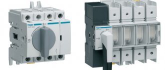
Distribution board diagram. Single-phase power comes from an input device with separated conductors PE and N. Two input single-pole 50 A circuit breakers are installed at the input. In the diagram they are paired and one two-pole circuit breaker can be used instead. Next, the power is supplied to the electricity meter and then distributed among the groups. The protective grounding conductor is connected to the PE bus, from which wiring is carried out throughout the premises. The working zero is connected to the N bus and then distributed among the groups.
The disadvantages of this scheme are the absence of a differential circuit breaker after the electric meter, which combines the functions of a residual current device (RCD) and a circuit breaker protecting electrical wiring from overcurrents (short circuit currents) and overload. The rating of this differential circuit breaker should be 50 A, the leakage current rating should be 30 mA, its shutdown time in the event of a short circuit should be less than the shutdown time of the input circuit breakers.
A 16 A circuit breaker and a 20 A RCD are installed on the group of kitchen and washing machine sockets, since the rating of the RCD must be greater than the rating of the circuit breaker installed in pair with it.
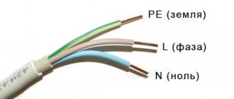
Diagram of a three-phase current input distribution device for an average private house with an outbuilding. A cable with conductors L1, L2, L3, and PEN is inserted into a plastic or metal cabinet. The PEN conductor is split (on the main grounding bus) into conductors N (working neutral) and PE (protective ground), which are connected to two copper busbars. Working neutrals from all groups come to the N bus; protective grounding wires coming from high-power devices are connected to the PE bus.
The phase wires go through the main three-phase circuit breaker to the meter. The working neutral is also connected to it. Then a three-phase RCD is installed, which protects the entire electrical circuit of the house. Next, the electric current is distributed along lines, protected, in turn, by automatic circuit breakers or RCDs.
The first three circuit breakers are designed to protect lighting circuits from overload and short circuit. A separate line, protected by a differential circuit breaker, is allocated for the kitchen outlet group. Next comes a group of sockets for other rooms, protected by an RCD and three circuit breakers. The last line, consisting of one RCD and two circuit breakers, is designed to protect the circuits of a separate room. All groups are powered from different phases L1, L2, L3, and protective devices are selected in accordance with a pre-designed circuit, taking into account the loads on each group and the operating conditions of the equipment.
Diagram of an apartment switchboard equipped (along with other protective devices) with a voltage relay. It indicates the ratings of all circuit breakers and electrical cable cross-sections. Energy consumers are divided into separate groups taking into account their functional characteristics. The input is made using a three-wire system (with a PE protective grounding conductor).
For electrical wiring, PVS brand cable is used here. This is a round flexible cable with double insulation and stranded conductors and is not recommended for hidden wiring. In addition, the ends of the cores of such a cable in numerous connections require tinning. It makes more sense to use VVG or NYM cable. Such a scheme may well be useful for organizing the power supply of a small private house.
The distribution board diagram can be made using the symbols adopted by the rules of the PUE. This diagram indicates the types and characteristics of protective devices, as well as their installation in specific groups.
The input type in the diagram shown is single-phase, with a PE protective conductor. The brand and cross-section of the wires are taken here in accordance with the ratings of the protective devices and the type of load.
The simplest electrical diagram of a distribution board in an apartment with single-phase input. It does not provide for the installation of an energy meter. There are three wires entering the apartment - L, N and PE. A circuit breaker is installed on the phase wire. Next comes the RCD, which protects the entire system from the possibility of electric shock to a person. The system is divided into nine consumer groups protected by automatic machines. Each group is connected to a PE protective grounding conductor.
The distribution board diagram of a private house with a sauna with a three-phase input without a protective PE grounding conductor, which is its main disadvantage. In this case, the short circuit of a phase wire to any open conductive body does not cause a short circuit necessary to trip the circuit breaker. In addition, an RCD is installed on the lines of the sauna, washing machine and group of kitchen sockets, which does not protect the circuits from overcurrents caused by overload or short circuit (the RCD does not respond to a short circuit). An RCD + automatic circuit breaker or differential circuit breakers should be installed here, combining the functions of an automatic device and an RCD.
For apartments of different layouts and degrees of comfort, we can offer several electrical circuits of distribution boards with the selection of ratings of protection devices.
Examples of electrical wiring diagrams
Each apartment power supply project is compiled taking into account the characteristics of the housing, types of power supply, as well as individual requests. In general, for high-quality subsequent installation, an electrician needs:
- Distribution board diagram
- Plan with placement of lighting fixtures, switches and control devices
- Layout of sockets and distribution board
- Plans and diagrams can be made in a fairly simplified form using conventional graphic symbols of specific devices. Their availability will help you select wires, as well as electrical and installation products necessary for installation
Connection diagram for a differential circuit breaker that performs the functions of an RCD and a circuit breaker.
Connection diagram of a common RCD with the output of the neutral conductor to the neutral bus. The rating of the RCD is an order of magnitude higher than the rating of the general circuit breaker.
Single line electrical diagram. It is a power supply system for a one-room apartment with a three-phase input and a PE protective conductor. It includes the results of network calculations and most fully reflects all its features. The types and characteristics of protective devices, the brand and cross-section of wires, and the power of consumers are indicated here. This scheme will allow you to properly equip and install the distribution board correctly.
See also:
- Berker switches, choice of colors, textures and shapes.
- Fontini switches, choice of colors, textures and shapes.
- THPG switches, choice of colors, textures and shapes.
- Lithoss switches, choice of colors, textures and shapes.
- Vimar Eikon Evo switches
- Art d'Arnould switches, choice of colors, textures and shapes.
- Hamilton switches, choice of colors, textures and shapes.
- Switch, purpose, characteristics
- Sockets, purpose, characteristics, device
- Electrical installation products, purpose
Instructions for checking voltage
You can measure this parameter in sockets in several ways:
- using an indicator;
- using a tester (multimeter or voltmeter);
- using modern tracking method.
User Electronics Engineer talked about the nuances of diagnosing this parameter on a household network and showed the procedure for performing the task.
Measuring with an indicator
We are talking about a special screwdriver, it is called a probe. The tip of this device must be inserted into one of the sockets of the socket. The type of screwdriver can be analog or digital; the nuances of its use differ. To diagnose, you need to close a special plate located on its handle with your finger.
If, as a result of connecting a screwdriver to the electrical network, the light indicator lights up, this is a phase, the other conductor is zero.
Types of screwdrivers
There are several types of devices:
- Conventional indicators equipped with a neon lighting source are based on a sting, a plastic case, a lamp, and a high-resistance resistor element. A contact plate made of steel is placed on the head of the device; a screwdriver can determine the phase contact and voltage in the electrical network. The advantages include ease of operation, high reliability and no battery. If there is current in the circuit, the indicator light will light up.
- Screwdrivers with built-in lights and batteries. Visually, they resemble simple testers, but the main feature is the ability to search for phase contact without touching the plate. Using the device, it is possible to test electrical wiring for breaks. To perform the task, the contact tip must be connected to one end of the electrical circuit, and the other must be touched with a finger. You need to touch the contact element on the head of the screwdriver; if the wiring is correct, the diode light will light up.
- Improved devices equipped with complex electronic components, but having a similar principle of operation. In addition to the main functions, they are suitable for non-contact detection of hidden electrical wiring if the layer of wall surface finishing is insignificant. The increased sensitivity of advanced screwdrivers allows you to determine the presence of a phase through one layer of insulation without the need to damage it. To switch from one operating mode to another, you must use the switch that the device is equipped with. Screwdrivers of this type are equipped with light and sound indicators.
Simple tester with neon indicator
Improved battery-powered screwdriver
Multifunction device with display
How to check with a multimeter
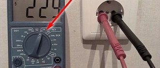
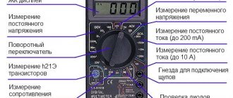
To measure using a tester, you need to do the following:
- First there is an automatic switching device for a 220-volt outlet. This element is located on the main panel of the switch and is marked on the equipment.
- The multimeter is activated. You need to find the knob on the device and turn the regulator towards alternating current. Then a voltage value is selected that is closer to that used in a household network. In this case - 220 volts.
- Two conductors with probes are connected to the measuring device - black and red. The first is negative, the second is positive. The multimeter has sockets of corresponding colors, so you won’t be able to mix them up.
- After connecting the contacts, they must be connected to the outputs of the sockets. Readings are then taken from the diagnostic tool. The voltage will be from 220 to 240 volts.
- The neutral slot is being diagnosed. It has L-shape type for all point directions. The scan tool's red pin goes to the hot slot, and then the black pin goes to the neutral output. As a result, the tester display will show a value of 110 and 120 volts. Then the red pin of the multimeter is connected to the hot slot, the resulting readings will be similar.
- All connected wires are disconnected, and the tester is deactivated.
Modern tracking
To constantly monitor the voltage parameter in the electrical network, you can install a monitoring relay. This is an automatic device that prevents overvoltage in the network. When installing it in an apartment or private house, the owner has the opportunity to monitor this parameter and prevent its jumps. But it is not advisable to install a control relay on a separate socket. The device is mounted on the most valuable electrical equipment or on the distribution panel.
What is the difference between volt and watt?
Watt (W or W) is a standard unit of measurement for power. Volt (V or V) is a standard unit of measurement for voltage, electrical potential difference, electrical potential, and electromotive force. The power (W) of any device can be calculated by multiplying the voltage (V) by the current (A).
Interesting materials:
How to enable voice dialing on Apple Watch? How to enable GX Control? How to enable feed in Google? How do I turn on the microphone on my headset? How to enable VK online notifications? How to enable mail ru mail forwarding? How to enable mail forwarding? How to enable charging percentage on MIUI 12? How to enable picture-in-picture mode on iPhone? How to enable Valet mode on an alarm?
Checking the connection
Socket for hob and oven
The voltage is checked in the outlet by connecting a voltmeter or tester. If it is present, the device will indicate how many volts it contains.
Socket voltage tester
The current strength can be determined by an ammeter connected in series with the operating load.
Electricians check the presence of voltage with an indicator. Single-pole - made in the form of a screwdriver with a light bulb. With its help you can find the phase, but it will not show the connection of the neutral wire. This can be done with a two-pole indicator, connecting it between phase and zero. You can easily check the voltage in the socket with a test lamp, which it should correspond to.
