What current does the motor consume from the network during startup and operation?
The passport of the electric motor indicates the current at the rated load on the shaft.
If, for example, 13.8/8 A is indicated, then this means that when the engine is connected to a 220 V network and at a rated load, the current consumed from the network will be equal to 13.8 A. When connected to a 380 V network, there will be a current of 8 A is consumed, that is, the power equality is valid: √ 3 x 380 x 8 = √ 3 x 220 x 13.8. Knowing the rated power of the motor (from the passport), you can determine its rated current. When the motor is connected to a three-phase 380 V network, the rated current can be calculated using the following formula:
I n = P n/ ( √3 U n x η x s osφ),
where P n is the rated power of the engine in kW, U n is the network voltage, in kV (0.38 kV). Efficiency factor (η) and power factor (with osφ) are the motor’s nameplate values, which are written on the shield in the form of a metal plate. See also - What passport data are indicated on the shield of an asynchronous motor.
Rice. 1. Electric motor passport. Rated power 1.5 kV, rated current at voltage 380 V – 3.4 A.
If the efficiency is not known. and the power factor of the engine, for example, if there is no passport plate on the engine, then its rated current with a small error can be determined by the ratio “two amperes per kilowatt”, i.e. If the rated power of the motor is 10 kW, then the current consumed by it will be approximately 20 A.
For the motor shown in the figure, this ratio also holds (3.4 A ≈ 2 x 1.5). More accurate current values when using this ratio are obtained with motor powers of 3 kW and above.
When the electric motor is idling, a small current is consumed from the network (no-load current). As the load increases, the current consumption also increases. As the current increases, the heating of the windings increases. Large overload leads to the fact that the increased current causes overheating of the motor windings, and there is a danger of charring of the insulation (burning out of the electric motor).
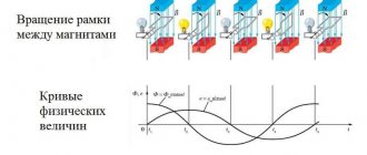
At the moment of starting from the network, the electric motor consumes the so-called starting current, which can be 3 to 8 times more than the rated current. The nature of the current change is presented on the graph (Fig. 2, a).
Rice. 2. The nature of the change in the current consumed by the motor from the network (a), and the effect of high current on voltage fluctuations in the network (b)
The exact value of the starting current for each specific engine can be determined by knowing the value of the starting current multiplicity - I start / I nom. The starting current multiplicity is one of the technical characteristics of the motor, which can be found in catalogs. The starting current is determined by the following formula: I start = I n x (I start / I nom). For example, with a rated motor current of 20 A and a starting current multiple of 6, the starting current is 20 x 6 = 120 A.
Knowing the actual value of the starting current is necessary for selecting fuses, checking the operation of electromagnetic releases during engine starting when selecting circuit breakers, and for determining the amount of voltage reduction in the network during startup.
The process of selecting fuses is discussed in detail in this article: Selecting fuses to protect asynchronous electric motors
A large starting current, for which the network is usually not designed, causes significant voltage drops in the network (Fig. 2, b).
If we take the resistance of the wires going from the source to the engine equal to 0.5 Ohm, the rated current I n = 15 A, and the starting current equal to five times the rated current, then the voltage loss in the wires at the time of starting will be 0.5 x 75 + 0, 5 x 75 = 75 V.
At the motor terminals, as well as at the terminals of nearby operating electric motors, there will be 220 - 75 = 145 V. Such a decrease in voltage can cause braking of operating motors, which will lead to an even greater increase in the current in the network and blown fuses.
In electric lamps, when the engines start, the heat decreases (the lamps “blink”). Therefore, when starting electric motors, they strive to reduce the starting currents.
To reduce the starting current, a motor starting circuit can be used with switching the stator windings from star to delta. In this case, the phase voltage will decrease by √ 3 times and the inrush current will be limited accordingly. After the rotor reaches a certain speed, the stator windings switch to a delta circuit and the voltage on them becomes equal to the rated one. Switching is usually done automatically using a time or current relay.
Rice. 3. Scheme for starting an electric motor with switching the stator windings from star to triangle
It is important to understand that not every engine can be connected according to this scheme. The most common asynchronous motors with an operating voltage of 380/200 V, including the motor shown in Figure 1, will fail when switched on according to this circuit. Read more about this here: Selecting a motor phase connection diagram
Currently, to reduce the starting current of electric motors, special microprocessor-based soft start devices (soft starters) are actively used. For more information about the purpose of this type of device, read the article Why a soft start of an asynchronous motor is needed.
Source: electricalschool.info
Download
I hope readers will forgive me for my free explanation of the processes - I tried to explain everything “on the fingers”. Who needs academic knowledge, please:
• V.L. Likhachev. Asynchronous electric motors. 2002 / The book is a reference book that describes in detail the design, operating principle and characteristics of asynchronous electric motors. Reference data is provided for engines of previous years of production and modern ones. Electronic starting devices (inverters), electric drives are described., djvu, 3.73 MB, downloaded: 7136 times./
• Bespalov, Kotelenets - Electrical machines / Transformers and electrical machines used in modern technology are considered. Their decisive role in the generation, distribution, conversion and utilization of electrical energy is shown. The basic theory, characteristics, operating modes, examples of designs and applications of electrical generators, transformers and motors are given., pdf, 16.82 MB, downloaded: 2317 times./
• MM. Katzman - Electrical Machines / Some say this is the best textbook on electrical engineering. The book discusses the theory, principle of operation, design and analysis of operating modes of electrical machines and transformers, both general and special purpose, which have become widespread in various branches of technology., pdf, 22.12 MB, downloaded: 2061 times./
• Electromash motor catalog / Asynchronous electric motors with squirrel-cage rotor - manufacturer’s catalog, pdf, 3.13 MB, downloaded: 1376 times./
• VEMZ engines catalog / Engine parameters and catalogue, pdf, 3.53 MB, downloaded: 1181 times./
• Dyakov V.I. Typical calculations for electrical equipment / Practical calculations for electrical equipment, theoretical information, calculation methods, examples and reference data., zip, 1.53 MB, downloaded: 2515 times./
• Karpov F.F. How to check the possibility of connecting several motors to the electrical network / The brochure shows the calculation of the electrical network for voltage fluctuations during the start-up and self-starting of asynchronous motors with squirrel-cage rotor and synchronous motors with asynchronous starting. The conditions under which starting and self-starting of engines are permissible are considered. The presentation of calculation methods is illustrated with numerical examples. The brochure is intended for qualified electricians as a guide when choosing the type of electric motors connected to a municipal or industrial power supply network., zip, 1.9 MB, downloaded: 1640 times./
• Operating manual for asynchronous motors / This manual contains the most important instructions for transportation, acceptance, storage, installation, commissioning, operation, maintenance, troubleshooting and troubleshooting for electric motors produced by Elektromashina. The operating manual is intended for three-phase asynchronous electric motors of low and high voltage series A, AIR, MTN, MTKN, 4MTM, 4MTKM, DA304, A4., pdf, 7.54 MB, downloaded: 2540 times./
• Catalog of AIR engines / Catalog of AIR engines - power from 0.12 to 315 kW; rotation speed 3000, 1500, 1000, 750 rpm; mains voltage 220/380 V, 380/660 V;, pdf, 1.07 MB, downloaded: 1044 times./
• Lomonosov, V.Yu.; Polivanov, K.M.; Mikhailov, O.P. Electrical engineering. / Lomonosov, V.Yu.; Polivanov, K.M.; Mikhailov, O.P. Electrical engineering. One of the best books on the basics of electrical engineering. The presentation begins with the very basics: it explains what voltage, current and resistance are, provides instructions for calculating the simplest electrical circuits, and talks about the relationship and interdependence of electrical and magnetic phenomena. Explains what alternating current is and how an alternating current generator works. It describes what a capacitor is and what an inductor is, what their role is in alternating current circuits. It is explained what three-phase current is, how three-phase current generators are designed and how its transmission is organized. A separate chapter is devoted to semiconductor devices: it talks about semiconductor diodes, transistors and thyristors; on the use of semiconductor devices for rectifying alternating current and as semiconductor switches. The achievements of microelectronics are briefly described. The last third of the book is entirely devoted to electrical machines, units and equipment: chapter 10 deals with direct current machines (generators and motors); Chapter 11 is devoted to transformers; AC machines (single-phase and three-phase, synchronous and asynchronous) are described in detail in Chapter 12; switches, electromagnets and relays are described in Chapter 13; Chapter 14 deals with electrical diagramming. The last, chapter 15, is devoted to measurements in electrical engineering. This book is a great way to learn the basics of electrical engineering, to understand the fundamental principles of the operation of electrical machines and units., zip, 13.87 MB, downloaded: 2653 times./
Another manual on motors: • Starting and protecting AC motors / Starting and protecting AC motors. Starting and braking systems for AC motors. Protection devices and fault analysis of AC motors. Guide to selecting protection devices. Manual from Schneider Electric, pdf, 1.17 MB, downloaded: 2042 times./
How to determine the power and current of an electric motor
All electric motors are produced with plates on the housing, from which you can find out the main characteristics of the electric motor: its brand, rated operating current and power consumption, rotation speed, motor type, efficiency and cos(fi). This data is also indicated in the passport for the device.
Of all the parameters, the most important for connection are: the power of the electric motor and the current consumption; this should not be confused with the starting one. It is these data that allow us to determine the sufficiency of power for the drive, the required cable cross-section for connecting the motor, and select the appropriate circuit breaker and thermal relay for protection.
Subscribe to the newsletter
The current needed to start an electric motor is called starting current. As a rule, the starting currents of electric motors are several times higher than the currents required for operation in a normally stable mode.
Figure 1. Asynchronous electric motor A large starting current of an asynchronous electric motor is necessary in order to spin the rotor from a standstill, which requires much more energy to be applied than to further maintain a constant number of its revolutions. It is worth noting that, despite a completely different operating principle, single-phase DC motors are also characterized by large starting currents.
High inrush currents for electric motors are undesirable because they can result in short-term power shortages for other equipment connected to the grid (voltage drop). Therefore, when connecting and setting up AC motors (the most common in industry), the task is always to minimize the values of starting currents, as well as to increase the smoothness of starting the motor through the use of special additional equipment. Such measures also make it possible to reduce the level of costs for starting an electric motor (use wires of a smaller cross-section, stabilizers and diesel power plants of lower power, etc.).
One of the most effective categories of devices that alleviate difficult starting conditions are soft starters and frequency converters. Their ability to maintain the starting current of AC motors for a long period—more than a minute—is considered especially valuable. Also, the starting current of an asynchronous electric motor can be reduced by introducing an external resistance into the rotor winding.
Calculation of the starting current of an asynchronous electric motor
Figure 2. Asynchronous electric motor with a frequency converter Calculation of the starting current of the electric motor may be required in order to select suitable circuit breakers that can protect the switching line of a given electric motor, as well as in order to select additional equipment (generators, etc.) suitable for the parameters.
The calculation of the starting current of the electric motor is carried out in several stages:
Determination of the rated current of a three-phase AC electric motor according to the formula: In=1000Pn/(Un*cosφ*√ηn). Рн here is the rated power of the engine, Un is the rated voltage, and ηн is the rated efficiency. Cosφ is the rated power factor of the electric motor. All this data can be found in the technical documentation for the engine.
Calculation of the starting current value using the formula Istart = In*Kpusk. Here In is the rated current value, and Startup is a multiple of the direct current to the rated value, which should also be indicated in the technical documentation for the electric motor.
Knowing exactly the starting currents of electric motors, you can correctly select circuit breakers that will protect the switching line.
How to determine the power of an electric motor
The easiest way is to look at the plate and find the value in kilowatts. For example, in the picture it is 45 kW.
Please note that this value on the plate indicates the active power consumed from the electrical network. The total power will be equal to the sum of active and reactive power. Electric meters in a house or garage count only the consumption of active electricity, and reactive energy is recorded only in enterprises using special meters. The higher the cos(fi) of an electric motor, the lower the reactive energy component of total power will be. Do not confuse cos(fi) with efficiency. This indicator shows how much electricity is converted into useful mechanical work, and how much into useless heat. For example, an efficiency of 90 percent means that a tenth of the electricity consumed is spent on heat losses and friction in the bearings.
You should keep in mind that the passport or plate indicates the rated power, which will be equal to this value only if the optimal load on the shaft is achieved. However, you should not overload the shaft for a number of reasons; it is better to choose a more powerful motor. At idle, the current will be much lower than the nominal value.
How to determine the rated power of an electric motor? On the Internet you will find many different formulas and calculations. For some, you need to measure the dimensions of the stator, for other formulas you will need to know the current value, efficiency and cos(fi). My advice is don't bother with all this. Practical measurements will still be better than these calculations. And you won’t need anything at all to carry them out.
How to determine the power of any electrical appliance in the house or garage? Of course, using an electricity meter. Before starting the measurement, unplug all electrical appliances from the sockets, lighting and everything connected to the electrical panel.
Next, if you have an electronic meter of the Mercury type, everything is very simple: you just need to turn on the motor under load and drive for about 5 minutes. The electronic display should display the load value in kW currently connected to the meter.
If you have a disk induction meter, keep in mind that it keeps records in kilowatt/hours. Write down the latest readings before starting measurements, turn on the engine strictly second per second for exactly 10 minutes, then after stopping, subtract the new readings from the previous ones and multiply kWh by 6. The result obtained will be the active power of this engine in Kilowatts; to convert to Watts, divide by 1000 I recommend reading the article: how to take electric meter readings.
If the engine is low-power , then for higher accuracy you can count the disk revolutions. For example, in one minute it made 10 full revolutions, and the meter says 1200 revolutions = 1 kW/h. We multiply 10 by the number of minutes in an hour and get 600 revolutions per hour. Divide 1200 by 600 and we get 500 watts or 0.5 kW. The longer you measure, the more accurate the data will be. But the time must always be a multiple of a full minute. Then divide 60 by the number of minutes of measurement and multiply by the counted revolutions. After this, we divide the value of revolutions equal to one Kilowatt/hour for your electric meter model by the result obtained and obtain the required amount of power.
How to protect your home from fire wiring
In a residential area, the power line must have protection elements. Calculation of parameters is simple. Calculate the total current that all electrical devices in the apartment will need if they are turned on at the same time. It is defined this way:
- sum up the power of the devices;
- divide the resulting number by the network voltage;
- the resulting parameter is calculated in amperes; it fixes the value that should be used when choosing protective elements.
Find out the maximum current value of the power line from the technician servicing your area. If it turns out that it involves less current consumption than you obtained when calculating the required value for all electrical appliances installed in the home (working simultaneously), reduce the parameter for which the protective elements are designed.
Follow the rule: never simultaneously connect to the network devices (food processor, kettle, air conditioner) that consume a total current exceeding the maximum power line parameter.
Important information! When electrical outlets have loose connections between the cord and the terminals, the wiring will not be able to handle the amperage it is designed to handle. To restore lost capacity, check the sockets and, if necessary, tighten the terminals. Be careful not to overtighten the screws, which could damage the outlet. Work is carried out with de-energized wiring.
How to determine the current consumption of an electric motor
Knowing the power , you can easily calculate the amount of current consumed. For 3-phase motors connected in a 380-volt star configuration, it is necessary to multiply the power in kilowatts by 2. For example, with a power of 5 kilowatts, the current will be 10 Amperes. Again, keep in mind that the motor will take such current only under a load as close as possible to the nominal value. A semi-loaded electric motor, and even more so at idle, will consume significantly less current.
To determine the current in single-phase networks, it is necessary to divide the power by voltage. For example, when the engine is running, the voltage at its connection point is 230 Volts. This is important because after turning on the load, the voltage will most likely drop at the point where the electric motor is connected.
If, for example, the power of a 220 Volt motor was measured to be 1.5 kW or 1500 Watts. Divide 1500 by 230 Volts and we find that the operating current of the motor is approximately 6.5 Amperes.
Battery selection
A car battery has many characteristics that need to be taken into account when choosing a new battery:
- Capacity. This value is expressed in Ah and reflects the maximum operating time of a fully charged battery. The choice based on it consists of comparing it with the car’s passport or the old standard battery model. The capacity is also selected according to the volume of the internal combustion engine. For example, to start engines up to 1.7 liters, it is enough to install a 55-60 A/h battery. If you have installed additional lighting or a fancy audio amplifier, we recommend a battery with a large parameter, but within the geometric dimensions. Since a more energy-intensive battery will have increased dimensions.
- Polarity. The location of the terminals determines the physical possibility of installing the battery in its original location and connecting the cables. For European cars, they usually buy batteries with direct polarity, for Russian cars - with reverse polarity, and for Asian cars they produce both. There are also universal ones, in which the terminals are located in the middle of the housing.
- Starting current. When you and I choose a battery and put it first, this is wrong. It is necessary to take into account the region and climatic conditions where the machine will be operated. If these are moderate latitudes with a normal climate, then there is no point in overpaying for more amps in the battery. If you need a frost-resistant source, the more amperes it has, the better, but the service life will be significantly shorter. We remind you that the inrush currents measured by different standards are different.
The table compares the characteristics of batteries of different performance standards:
| SAE/CCA | EN | IEC | DIN |
| 350 | 330 | 225 | 200 |
| 400 | 360 | 260 | 225 |
| 450 | 420 | 290 | 255 |
| 500 | 480 | 325 | 280 |
| 550 | 520 | 355 | 310 |
| 600 | 540 | 390 | 335 |
Motor starting current
When starting any type of electric motor, a starting current occurs from 2 to 8 times the rated current in the operating mode of the electric motor. The magnitude of the starting current depends on the type of motor, rotation speed, connection diagram, presence of load on the shaft and other parameters.
The starting current occurs because at the moment of starting a very strong magnetic field is induced in the windings, which is necessary to move and spin the rotor. When the motor is turned on, the resistance of the windings is low, and therefore, according to Ohm’s law, the current increases at a constant voltage in the circuit section. As the motor spins up, an emf or inductive reactance appears in the windings and the current begins to decrease to the rated value.
These surges of reactive energy negatively affect the operation of other electrical consumers connected to the same power line, which causes voltage surges or surges that are especially destructive for electronics.
Reasons for installing current transformers
Current transformer RTP-58
The device is designed to transform the primary current value to a safe value for the network. Transformers are also used for the following purposes:
- delineation of low-voltage metering equipment and relays connected to the secondary winding, if there is a primary high voltage in the network;
- increase or decrease in voltage readings;
- measuring the state of the electrical network and alternating current parameters;
- ensuring the safety of repair and diagnostic work;
- quick activation of relay protection in case of short circuits;
- energy consumption accounting - an electric meter is usually combined with them.
To measure, you will need to connect the CT to the wire gap, and connect a voltmeter or ammeter combined with a resistor to the secondary mark.
Starting currents of asynchronous electric motors
Asynchronous motors, when connected to the mains, consume a significant amount of energy in order to:
- set the rotor in motion;
- increase the rotation speed from zero to the operating level.
This explains the need to use a large starting current, which differs significantly from the amount of electricity that allows maintaining a constant speed. This is typical not only for asynchronous, but also for single-phase DC motors, although the operating principle of the latter is completely different.
Methods for checking PT
Can you trust the numbers provided by the manufacturer? It's a purely individual matter. Batteries from lesser known brands are really worth researching. But how can you check the starting current of the battery yourself, because, as we found out, this characteristic is very important?
There are several ways to do this using “folk” methods, but, let’s be honest, all of them are not highly accurate - for this you need to use expensive professional equipment.
A multimeter is not suitable for these purposes, and you will not find a description online of how to measure the starting current of a battery with such a device. The fact is that the multimeter is not designed to measure current ratings of several hundred amperes - if there are separate models that are able to do this, they will be too expensive.
So you will have to use less accurate methods:
- using a load fork, which is a voltmeter equipped with an additional resistance. The load plug, when connected to the battery terminals, acts as a load, replacing the on-board network of the machine;
- current clamps. This is the most affordable device for measuring the starting current of a car battery; it is not afraid of large amperages;
- The “grandfather” test consists of turning on the low beam on the car. If the brightness of the lamp does not change for 5-10 minutes, we can say that the battery is working. In this way, you can cut off a known problem battery when purchasing it;
- The “hearing” test is basically carried out every time we start the car. If the fuel system is in good condition, the engine should start in 2-4 seconds. When it takes more than 10 seconds, we can say that its starting current is insufficient.
High inrush current problem: solution
High inrush current can cause a sudden, albeit short-term voltage drop, causing other devices connected to the network to experience a lack of power. This is undesirable because it negatively affects the safety of operation and the durability of the equipment.
To solve the problem, special additional devices are provided, the installation of which during the process of connecting and adjusting the engines allows:
- reduce the starting current as much as possible;
- improve startup smoothness;
- reduce the cost of starting the unit, since it becomes possible to use less powerful diesel power plants, stabilizers, wires with a smaller cross-section, etc.
The most effective are modern devices such as frequency converters and soft starters. They provide a high (more than a minute) duration of maintaining the inrush current.
What problems arise when starting loads increase?
The amplitude of the starting surge is influenced by the structural features and how high the quality of the transformer is. Network impedance also matters. If it is low, more throw will occur. When starting, the coils take a lot of electricity for some time, until the parameters in the core are restored.
The inrush current heats up the elements of the power supply. This can cause their failure as a result of burning of the contacts in the switches due to the appearance of an “arc”. The overestimated starting throw is smoothed out when using additional elements of the so-called “soft start”. Starting surges and the supply of excessive voltage return to normal, and therefore the activation of safety devices is eliminated.
How to calculate the starting current of an electric motor
In order to objectively assess the complexity of the engine starting conditions, it is necessary to first know the amount of starting current required for this. The main calculation steps are as follows:
- calculation of rated current;
- determination of the starting current value (in amperes).
In order to obtain the value of the rated current for the used electric motor model, use a formula that has the form Iн=1000Pн / (Un*cosφ*√ηн). Pн and Un are the rated power and voltage indicators, cosφ and ηн are the rated power and efficiency factors.
The actual starting current, which is designated as Iп, is determined using the formula Iп = Iн * Kп, where Kп is the multiple of the direct current in relation to its rated value (Iн). All information necessary for calculations (values of Kp, Pn, ηn, cosφ, Un) can be found in the technical documentation that comes with the electric motor.
Correct calculation of the motor starting current facilitates the correct selection of circuit breakers designed to protect the switching line, as well as the purchase of additional equipment (generators, etc.) with suitable parameters.
Source: www.szemo.ru
How to choose a circuit breaker for your engine
The correct selection of a circuit breaker to protect an electric motor is of great importance for the equipment. Reliability of operation, protection of the engine from emergency operating conditions and wiring directly depend on the selection of the circuit breaker.
In this article we will outline the conditions for choosing a circuit breaker to protect an electric motor. In order to choose a circuit breaker you need to know:
— rated motor current;
— multiple of the starting current to the rated current;
— maximum permissible electrical wiring current.
Motor rated current
- this is the current that the electric motor has during operation at rated power. It is indicated on the electric motor passport or taken from the electric motor passport data tables.
Multiplicity of starting current to rated current
– this is the ratio of the starting current that occurs in the electric motor during start-up to the rated current. It is also indicated on the electric motor passport or in the electric motor tables.
Maximum permissible wiring current
- this is the permissible current that can pass through a wire or cable that is connected to an electric motor.
Conditions for correct selection of circuit breaker
to protect the electric motor:
— the rated current of the circuit breaker must be greater than or equal to the rated current of the electric motor. For example: electric motor current AIR112M4U2 In. dv. =11.4A, select the VA51G2534 circuit breaker for rated current In. = 25A and release current IN..ras. = 12.5A.
After this, we will check that the circuit breaker does not trip when starting the electric motor using the following condition:
Iu.e.>kzap. · kр.у · kр.п. ·In.dv ·ki
where Kzap . — safety factor that takes into account voltage fluctuations, Kzap. = 1.1;
kр.у - coefficient that takes into account the inaccuracy of the insertion of the operating current of the electromagnetic release of the circuit breaker, Kр.у = 1.2;
Starting currents of electrical equipment
Electricity users are not left indifferent by the power of electrical appliances that surround us in everyday life, because in the end it comes down to the capabilities of our wallet. We take into account the total power from the figures indicated in the documentation for electrical appliances when designing a future network, however, we do not always take into account that the manufacturer indicates the electrical characteristics for equipment operating in nominal mode.
In real conditions, most electrical appliances exceed their rated power, reaching their maximum load the moment they are turned on. This happens due to inrush currents, which for a short period of time (from tenths to several seconds) exceed the rated current consumption by up to 10 times.
These features are typical for electrical appliances that have electric motors (refrigerators, air conditioners, electric pumps), and electric heating devices using heating elements. Oddly enough, even ordinary incandescent lamps have fairly high inrush current values from 5 to 13 times higher than the rated values (it’s not for nothing that they almost always burn out the moment they are turned on).
Nature of inrush currents
It is easy to illustrate the reason for the occurrence of inrush current using a simple example. Anyone who has ever ridden a bicycle knows that the first turns of the pedals require the most effort, when the bicycle starts moving; then, when the rated speed is reached, it is much easier to do this.
Similar processes occur when starting an electric motor, because to overcome the inertia of the motor shaft and associated mechanisms, a powerful electromagnetic field is required, which operates until the operating speed is reached. It is characterized by higher currents when starting the engine, related to the rated values using starting current coefficients (multiple of the starting current to the rated value).
The nature of inrush currents is different for incandescent lamps. The resistance value of the tungsten filament of a 100-watt light bulb in a cold (off) state is 40 Ohms, and in a hot (on) state it is 490 Ohms. It is not surprising that the current at the moment of switching on is more than 12 times higher than the rated current of the lamp. The resistance of the nichrome filament of the heating element of an electric heating device changes in a similar way.
Power supply specifications
Today, creating an IP with a power of up to 1 kW is not a difficult technical task. The availability of the element base and a large number of developments in this area make it possible to quickly set up the production of power supplies based on known components and according to well-known recommendations. It is not surprising that the circuit design, technical characteristics and appearance of inexpensive rectifier devices from both the world's leading manufacturers and little-known companies are very similar.
One of the inexpensive power sources often used to power LED strips are the LRS manufactured by MEAN WELL (Figure 1). When developing this line, both the latest achievements in the production of switching power supplies and the most modern element base were used, which made it possible to bring the LRS family of power supplies to a modern technical level and provide a good price/quality ratio.
Rice. 1. Rectifier from the LRS family
The key features of the LRS family (Table 1) are the ability to operate in a universal input voltage range (85...264 V AC), compact size (profile height 1U - 30 mm), high efficiency (up to 91.2%) and low consumption when the load is turned off. (0.2...0.75 W). The LRS family of power supplies have many certificates, including IEC/EN 60335-1 (PD3) and IEC/EN61558-1, 2-16. All LRS power supplies are tested at 100% load and come with a three-year warranty.
Table 1. Main technical characteristics of rectifiers of the LRS family
| Name | Rated output power, W | Output voltage, V | Input voltage V AC | Current consumption at 230 V AC, A | Starting current at 230 V AC, A |
| LRS-35 | 35 | 5…48 | 85…264 | 0,42 | 45 |
| LRS-50 | 50 | 3,3…48 | 85…264 | 0,56 | 45 |
| LRS-75 | 75 | 5…48 | 85…264 | 0,85 | 65 |
| LRS-100 | 100 | 3,3…48 | 85…264 | 1,2 | 50 |
| LRS-150 | 150 | 12…48 | 85…132/170…264 | 1,7 | 60 |
| LRS-150F | 150 | 5…48 | 85…264 | 1,7 | 60 |
| LRS-200 | 200 | 3,3…48 | 90…132/180…264 | 2,2 | 60 |
| LRS-350 | 350 | 3,3…48 | 90…132/180…264 | 3,4 | 60 |
One of the specific features of LED lighting is the ability to install equipment in specialized electrical cabinets, therefore, along with power supplies in perforated housings, in practice there may be a real need for modules with a form factor designed for installation on a DIN rail. In this case, you should pay attention to the HDR produced by MEAN WELL , produced in small-sized plastic cases (Figure 2).
Rice. 2. Appearance of rectifiers of the HDR family produced by MEAN WELL
Although HDR rectifiers were originally designed for use in automated control systems and have insulation ratings up to Class II, their applications are not limited to powering industrial controllers. Thanks to a wide range of input voltages, a good level of electrical safety, high efficiency and low power consumption when the load is turned off (no more than 0.3 W), these modules (Table 2) can be successfully used in a wide variety of applications, from powering elements of complex technological lines to the same LED lighting.
Table 2. Main technical characteristics of rectifiers of the HDR family
| Name | Maximum output power, W | Output voltage, V | Input voltage, V AC | Current consumption at 230 V AC, A | Starting current at 230 V AC, A |
| HDR-15 | 15 | 5…48 | 85…264 | 0,25 | 45 |
| HDR-30 | 36 | 5…48 | 85…264 | 0,48 | 25 |
| HDR-60 | 60 | 5…48 | 85…264 | 0,8 | 60 |
| HDR-100 | 100 | 12…48 | 85…264 | 1,6 | 70 |
| HDR-150 | 150 | 12…48 | 85…264 | 1,6 | 70 |
Analyzing the data in tables 1 and 2, you can see that for all considered power supplies the starting current is tens of times higher than the current consumed at maximum load. Moreover, the lower the power of the power source, the greater this ratio. For example, for the lowest-power of the models considered - IP HDR-15, the starting current (45 A), according to the technical documentation, is 180 times higher than the maximum value during operation (0.25 A). For powerful rectifiers, this ratio, although slightly smaller, is still quite large. The absolute record for the highest starting current (70 A) belongs to the HDR-150 . With such a starting current, at the moment the device is turned on, although briefly, it will consume about 15 kW, which is quite a lot even for industrial equipment.
The introduction of a power factor corrector (PFC) into the IP does not help the situation. If we analyze the technical characteristics of the modules of the RSP family manufactured by MEAN WELL (Figure 3), which differ from the LRS rectifiers discussed above by the presence of an active power factor corrector, it turns out that their starting currents also exceed the rated values by 15...70 times (Table 3). This is, of course, less than in modules without PFC, but it is still a lot, even despite the high power factor (at least 0.93).
Rice. 3. RSP family rectifier manufactured by MEAN WELL
Table 3. Main technical characteristics of rectifiers of the RSP family
| Name | Maximum output power, W | Output voltage, V | Input voltage, V AC | Current consumption at 230 V AC, A | Starting current at 230 V AC, A |
| RSP-75 | 75 | 3,3…48 | 85…264 | 0,5 | 35 |
| RSP-100 | 100 | 3,3…48 | 85…264 | 0,55 | 30 |
| RSP-150 | 150 | 3,3…48 | 85…264 | 0,8 | 45 |
| RSP-200 | 200 | 2,5…48 | 88…264 | 1,1 | 40 |
| RSP-320 | 320 | 2,5…12 | 88…264 | 1,5 | 40 |
| RSP-500 | 500 | 3,3…48 | 85…264 | 2,65 | 40 |
Electric motor power calculation
Electric motor power by current can be calculated using our online calculator:
The result can be rounded to the nearest standard power value.
Standard values of electric motor power : 0.25; 0.37; 0.55; 0.75; 1.1; 1.5; 2.2; 3.0; 4.0; 5.5; 7.5; eleven; 15; 18.5; 22; thirty; 37; 45; 55; 75 kW, etc.
Engine power is calculated using the following formula:
P=√3UIcosφη
- U - Rated voltage (voltage to which the electric motor is connected);
- I - Rated current of the electric motor (taken from the passport data of the electric motor , and in their absence is determined by calculation);
- cosφ - Power factor - the ratio of active power to total power (taken from 0.75 to 0.9 depending on the power of the electric motor);
- η - Efficiency factor - the ratio of the electrical power consumed by the electric motor from the network to the mechanical power on the motor shaft (taken from 0.7 to 0.85 depending on the power of the electric motor);
Main types of electric motors
There are many types and modifications of electric motors. Each of them has its own power and other parameters.
The main classification divides these devices into DC and AC motors. The first option is used much less frequently, since its operation requires the presence of a direct current source or a device that converts alternating voltage into direct current. Fulfilling this condition in modern production will require significant additional costs.
But, despite significant disadvantages, DC motors have a high starting torque and operate stably even at high overloads. Due to their qualities, these units are widely used in electric transport, in the metallurgical and machine tool industries.
However, most modern equipment runs on AC motors. The operation of these devices is based on electromagnetic induction, which is created in a magnetic field by a conducting medium. The magnetic field is created using windings flowing around currents or using permanent magnets. Electric motors operating on alternating current can be synchronous or asynchronous.
The use of synchronous electric motors is practiced in equipment where a constant rotation speed is required. These are DC generators, pumps, compressors and other similar installations. Different models differ in their own technical characteristics. For example, the rotation speed can be in the range of 125-1000 rpm, and the power reaches 10 thousand kilowatts.
Many designs have a short-circuited winding located on the rotor. With its help, if necessary, an asynchronous start is made, after which the synchronous motor continues to operate as usual, minimizing electrical energy losses. These engines are characterized by their small size and high efficiency.
Asynchronous AC motors have become much more widespread in the manufacturing sector. They are characterized by a very high frequency of rotation of the magnetic field, significantly exceeding the speed of rotation of the rotor. A significant disadvantage of these devices is considered to be a decrease in efficiency to 30-50% of the norm at low loads. In addition, during start-up, the current parameters become several times greater compared to operating indicators. These problems are eliminated by using frequency converters and soft starters.
Asynchronous motors are used in those facilities where frequent switching on and off of equipment is required, for example, in elevators, winches, and other devices.
Motor current calculation
The rated and starting current of an electric motor can be calculated by power using our online calculator:
The rated motor current is calculated using the following formula:
Inom=P/√3Ucosφη
- P - Rated power of the electric motor (taken from the motor’s passport data or determined by calculation);
- U - Rated voltage (voltage to which the electric motor is connected);
- cosφ - Power factor - the ratio of active power to total power (taken from 0.75 to 0.9 depending on the power of the electric motor);
- η - Efficiency factor - the ratio of the electrical power consumed by the electric motor from the network to the mechanical power on the motor shaft (taken from 0.7 to 0.85 depending on the power of the electric motor);
The starting current of the electric motor is calculated using the formula:
Istart=Inom* K
- K - Starting current multiplicity, this value is taken from the electric motor passport, or from catalog data (in the above online calculator, the starting current multiplicity is determined approximately based on the other specified characteristics of the electric motor).
Real current measurements
As I said above, in my opinion the best way to “see” the inrush current is to use an active (resistive) shunt and look at the voltage on it with an oscilloscope.
I use this shunt:
Shunt for measuring inrush current using an oscilloscope
The subject is a geared motor that turns a vertical auger through a chain transmission:
Geared motor on which we measure the starting current
The auger was full at the time of start-up, so its operating current (7.7 A, measured with clamps) was almost equal to the rated current (8.9 A, visible on the nameplate).
Vertical auger motor nameplate
The inrush current situation is visible on the oscilloscope:
Inrush current waveform 500 ms/div
Let's bring the moment of interest closer by accelerating the scan to 100 ms/div:
Inrush current waveform 100 ms/div
Here it is already easy to see the sine of the supply current and estimate the multiplicity factor of the starting current Kp, which is approximately equal to 4.
Let's bring the moment of truth even closer (up to 50 ms/div):
Motor starting moment – starting current
Here the transient processes caused by the inductance and self-inductive emf of the motor windings are already clearly visible. This pulse, the duration of which is much less than the network period of 20 ms, provides good interference with a wide spectrum into the power supply network and radio air.
Another reason to use an inverter? Not really, the situation with interference there is much worse!
For those who don’t want to bother, I repeat – there are clamps with the Inrush function that can measure inrush current.
Calculation of electric motor power factor
Online calculation of power factor (cosφ) of an electric motor
Calculation of cosφ (cosine phi) of the engine is carried out using the following formula:
cosφ=P/√3UIη
- P - Rated power of the electric motor (taken from the motor’s passport data or determined by calculation);
- U - Rated voltage (voltage to which the electric motor is connected);
- I - Rated current of the electric motor (taken from the passport data of the electric motor , and in their absence is determined by calculation);
- η - Efficiency factor - the ratio of the electrical power consumed by the electric motor from the network to the mechanical power on the motor shaft (taken from 0.7 to 0.85 depending on the power of the electric motor);
Connecting an asynchronous motor
The stator winding of almost any such device has six terminals (of which three are the beginning and three are the ends). Depending on the power supply network of the motor, these terminals are connected either in a “star” or in a “triangle”. For this purpose, the housing of each motor has a box in which the starting and ending wires of the windings are located (they are designated, respectively, C1, C2, C3 and C4, C5, C6).
Star connection
This is the name for the method of connecting windings in which all three windings have one common point (neutral). The linear voltage of such a connection is 1.73 times higher than the phase voltage. Low starting currents are considered a positive quality of this type of connection, although the power losses are quite significant.
The delta connection method differs in that with this method the connection is made in such a way that the end of one winding becomes the beginning of the next.
Delta connection
In this case, the connection phase and linear voltages are the same, therefore, with a linear voltage of 220 volts, the correct connection of the windings will be a triangle. The positive side of this connection is high power, while the negative side is high starting currents.
To reverse (change the direction of rotation) of a three-phase asynchronous motor, it is enough to swap the leads of its two phases. In production, this is done using a pair of magnetic starters with dependent switching.
Significant starting currents for asynchronous motors are a very undesirable phenomenon, because they can lead to a voltage shortage effect for other types of equipment connected to the same network. This was the reason that when connecting and setting up motors of this type, the task arises of minimizing starting currents and increasing the smoothness of starting motors by using specialized equipment. The most effective types of such devices are soft starters and frequency converters. One of their most valuable qualities is that they are able to maintain the motor starting current for quite a long time (usually more than a minute).
In addition to the standard method of turning on asynchronous motors, there are also methods for connecting them to a supply network that has only one phase.
Capacitor starting of an asynchronous motor
For this purpose, the capacitor switching method is mainly used. The capacitor can be installed either alone or in pairs (one starting and the second working). A pair of condensers is installed when there is a need to change the capacity during start-up and operation, which is done by connecting and disconnecting one of the condensers (starting). For this, as a rule, paper containers are used, since they do not have polarity, and when operating on alternating current, this is very important.
To calculate the working capacitor there is the following formula:
Avg=4800(i/u).
The starting capacitor must have a capacity two to three times greater than the operating capacitor and an operating voltage one and a half times higher than the supply voltage.
The starting and running capacitors are connected in parallel, so that in parallel with the starting capacitor, a shunt resistor is switched on and one end of the starting capacitor is switched on through a switch. When starting the engine, the key is closed, increasing the starting current, then it is opened.
However, we must not forget that not every engine can be connected to a single-phase network. In addition, the power of the motor in such a connection will be only 0.5-0.6 of the power of a three-phase connection.