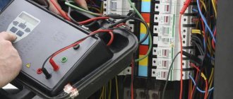
It is not so often necessary to find out exactly the frequency of alternating current, compared to indicators such as voltage and current. For example, in order to measure the current strength, you can use a measuring clamp; for this you don’t even have to come into contact with conductive parts, and any pointer or digital multimeter checks the voltage. However, to check the frequency with which the polarity changes in alternating current circuits, that is, the number of its full periods, a frequency meter is used. In principle, a device with the same name can also measure the number of mechanical vibrations over a certain period of time, but in this article we will talk exclusively about the electrical quantity. Next, we will tell you how to measure the frequency of alternating current with a multimeter and frequency meter.
Direct and alternating current
From a physics course we know that electric current is the directed movement of electrons.
With direct current, the polarity of charged particles is constant. Therefore, all devices designed to operate from it always have polarity markings for correct connection to the network. Otherwise, the device simply will not work and may also fail.
Alternating current is safer in this regard. Since its polarity is constantly changing, it does not have a detrimental effect on connected electrical appliances. Appliance plugs and AC outlets do not have polarity markings, so you can safely plug them into the network without worrying about the correct position of the contacts.
But the main advantage of alternating current is the great ability to regulate the network voltage using transformers. That is why alternating current has become much more widespread throughout the world than direct current.
What devices can be used
Classification of frequency meters
All these devices are divided into two main groups according to their area of application:
- Electrical measuring. They are used for household or industrial frequency measurement in alternating current circuits. They are used for frequency regulation of the speed of asynchronous motors, since the type of frequency measurement of revolutions, in this case, is the most effective and widespread.
- Radio measuring. They are used exclusively in radio engineering and can measure a wide range of high-frequency voltages.
By design, frequency meters are divided into panel-mounted, stationary and portable. Naturally, portable devices are more compact, versatile and mobile, which are widely used by radio amateurs.
For any type of frequency meter, the most important characteristics that, in principle, a person should pay attention to when purchasing are:
- The range of frequencies that the device can measure. When planning to work with the standard industrial value of 50 Hz, you need to carefully read the instructions, since not all devices will be able to see it.
- Operating voltage in the circuits in which the measuring work will take place.
- Sensitivity, this value is more important for radio frequency devices.
- The error with which he can make measurements.
AC Frequency Multimeter
The most common device with which you can find out the magnitude of frequency fluctuations and which is freely and widely available is a multimeter. You need to pay attention to its functionality, since not every such device will be able to measure the frequency of alternating current in an outlet or other electrical circuit.
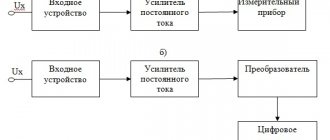
Such a tester is most often made very compact so that it fits easily in a bag and is as functional as possible, measuring, in addition to frequency, also voltage, current, resistance, and sometimes even air temperature, capacitance and inductance. The modern type of multimeter and its circuit are based purely on digital electronic elements for more accurate measurements. This multimeter consists of:
- Liquid crystal informative indicator for displaying measurement results, located, most often, in the upper part of the structure.
- The switch is basically made in the form of a mechanical element that allows you to quickly move from measuring one quantity to another. You need to be very careful, because, for example, if you measure voltage and the switch is set to o, that is, the current strength, then the consequence of this will inevitably be a short circuit, which will not only lead to failure of the device, but can also cause a thermal burn the arc of a person's arms and face.
- Probe socket. With their help, there is a direct electrical connection between the device and the measured conductive object. The wires should not have cracks or breaks in the insulation, especially their tips, which will be in the hands of the person measuring.
I would also like to mention special attachments for the multimeter, which exist and are designed specifically to increase the number of functions of a conventional device with a standard set.
Why is AC frequency important?
Alternating current is widely used in household and industrial electrical networks. For the normal operation of any devices and equipment, it is extremely important that the frequency of the current is constant. If it fluctuates by more than 1%, the efficiency of any machines and mechanisms connected to the network, or household appliances, significantly decreases.
In industrial production, a sharp change in the frequency of the current used can lead to manufacturing defects and even equipment breakdown.
There is a frequency standard for electric current:
- 50 Hz – Russia, countries of the former USSR, Europe, the Baltic states, North Korea, Australia;
- 60 Hz – USA, Canada, Taiwan, South Korea, Cuba, Costa Rica and others.
But, for example, in Japan both frequencies are used. In the western regions of the country, the standard frequency is 60 Hz, and in the eastern regions - 50 Hz.
What devices can be used
Classification of frequency meters
All these devices are divided into two main groups according to their area of application:
- Electrical measuring. They are used for household or industrial frequency measurement in alternating current circuits. They are used for frequency regulation of the speed of asynchronous motors, since the type of frequency measurement of revolutions, in this case, is the most effective and widespread.
- Radio measuring. They are used exclusively in radio engineering and can measure a wide range of high-frequency voltages.
By design, frequency meters are divided into panel-mounted, stationary and portable. Naturally, portable devices are more compact, versatile and mobile, which are widely used by radio amateurs.
For any type of frequency meter, the most important characteristics that, in principle, a person should pay attention to when purchasing are:
- The range of frequencies that the device can measure. When planning to work with the standard industrial value of 50 Hz, you need to carefully read the instructions, since not all devices will be able to see it.
- Operating voltage in the circuits in which the measuring work will take place.
- Sensitivity, this value is more important for radio frequency devices.
- The error with which he can make measurements.
AC Frequency Multimeter
The most common device with which you can find out the magnitude of frequency fluctuations and which is freely and widely available is a multimeter. You need to pay attention to its functionality, since not every such device will be able to measure the frequency of alternating current in an outlet or other electrical circuit.
Such a tester is most often made very compact so that it fits easily in a bag and is as functional as possible, measuring, in addition to frequency, also voltage, current, resistance, and sometimes even air temperature, capacitance and inductance. The modern type of multimeter and its circuit are based purely on digital electronic elements for more accurate measurements. This multimeter consists of:
- Liquid crystal informative indicator for displaying measurement results, located, most often, in the upper part of the structure.
- The switch is basically made in the form of a mechanical element that allows you to quickly move from measuring one quantity to another. You need to be very careful, because, for example, if you measure voltage and the switch is set to o, that is, the current strength, then the consequence of this will inevitably be a short circuit, which will not only lead to failure of the device, but can also cause a thermal burn the arc of a person's arms and face.
- Probe socket. With their help, there is a direct electrical connection between the device and the measured conductive object. The wires should not have cracks or breaks in the insulation, especially their tips, which will be in the hands of the person measuring.
How to measure frequency with a multimeter?
In ordinary life, it is not so often necessary to measure the frequency of electric current, since it is maintained centrally in the network. Deviations, if any, are less than 1%.
You can determine the frequency of the current produced by any device using a special frequency meter. But such devices are rarely found in a home craftsman’s kit. They are mainly used by professionals. But nowadays almost everyone has a digital multimeter.
Some (not all) multimeter models are equipped with an AC frequency measurement feature. If it exists, then it will be easy to find out this parameter.
The procedure is as follows:
- The probes are connected to the appropriate sockets according to the instructions.
- The mode switch is set to measure the frequency of alternating current.
- To begin with, you can measure the frequency in the 220 V network. It is supported by the electricity supplier and is equal to 50 Hz. The frequency is measured with a multimeter by connecting the probes of the device to the contacts of the socket. If the result differs slightly from the standard frequency, this should be taken into account as an instrument error. And make corrections for it during the next measurements.
- Next, you can measure the frequency parameter of the device that interests you.
Thus, the multimeter allows you to determine with sufficient accuracy the frequency of the current in the network or at the output of electrical generators, converters, and filtering devices.
Now you know how to measure frequency with a multimeter. We wish you safe and accurate measurements!
Circuit of a simple frequency meter
The frequency meter circuit is quite simple; most functions are performed by a microcontroller. The only thing is that the microcontroller needs an amplification stage to increase the input voltage from 200-300 mV to 3 V. A transistor connected in a common-emitter circuit provides a pseudo-TTL signal fed to the microcontroller input. Some kind of “fast” transistor is needed as a transistor; I used BFR91, a domestic analogue of the KT3198V.
The voltage Vke is set at 1.8-2.2 volts by resistor R3* in the circuit. Mine is 22 kOhm, but adjustments may be required. The collector voltage of the transistor is applied to the counter/timer input of the PIC microcontroller through a 470 ohm series resistance. To turn off the measurement, the built-in pull-down resistors are used in the PIC. The PIC implements a 32-bit counter, partly in hardware, partly in software. The counting begins after the built-in pull-down resistors of the microcontroller are turned off, the duration is exactly 0.4 seconds. After this time, the PIC divides the resulting number by 4, and then adds or subtracts the appropriate intermediate frequency to obtain the actual frequency. The resulting frequency is converted for display on the display.
In order for the frequency meter to work correctly, it must be calibrated. The easiest way to do this is to connect a pulse source with a precisely known frequency in advance and rotate the tuning capacitor to set the required readings. If this method is not suitable, then you can use “rough calibration”. To do this, turn off the power of the device, and connect pin 10 of the microcontroller to GND. Then, turn on the power. The MK will measure and display the internal frequency.
If you cannot adjust the displayed frequency (by adjusting the 33 pF capacitor), then briefly connect pin 12 or 13 of the MK to GND. This may need to be done several times since the program only checks these pins once per measurement (0.4 sec). After calibration, disconnect the 10th leg of the microcontroller from GND without turning off the power to the device in order to save the data in the non-volatile memory of the MK.
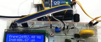
I drew a printed circuit board for my case. This is what happened: when power is applied, a screen saver pops up briefly and the frequency meter goes into measurement mode, there is nothing at the input:
Software part
Code for ATtiny414
When writing code for the ATtiny414 and its binding, I found the AVR1000b documentation useful: Getting Started with Writing C-Code for AVR MCUs. Also, when choosing characters for specific case settings, it would be a good idea to read iotn414.h, which is located on your PC in megaTinyCore.
OLED display
In the display interface, I used the same functions as in many previous projects, for example Tiny Function Generator, which used the same I2C OLED display.
The text is drawn using a 6x8 pixel character set, but at double the scale, the smoothing function I described in Smooth Big Text is used to produce 12x16 pixel characters. Note that on the ATtiny414 in megaTinyCore the I2C buffer size is only 16 bytes to save RAM, so I had to change the ClearDisplay and PlotChar() functions to send data in smaller chunks.
I adjusted the Plotlnt() function to display commas between each triple of digits to make them easier to read.
Real time clock
Configuring an RTC to use an external crystal is more difficult than it may seem, since the clock controller is protected from accidental tampering by the Change Configuration Protocol (CCP). For this reason, before each adjustment is made, this action must be activated. It's good that there is a note in the application explaining how to do this, and I wrote the code using the example from this note.
Timer/counter TCD0
TCD0 is configured to count from 0 to 0xFFF and capture the counter value into the CAPTUREB register when event B is received. It generates interrupts on capture events as well as counter overflows, and is clocked by an external signal via the EXTCLK/PA3 pin: void TCDSetup() { TCD0.CTRLB = TCD_WGMODE_ONERAMP_gc; // Setting the counter mode TCD0.CMPBCLR = 0xFFF; // Countdown to maximum TCD0.INPUTCTRLB = TCD_INPUTMODE_EDGETRIG_gc; // Capture and reset counter TCD0.EVCTRLB = TCD_CFG_ASYNC_gc | TCD_ACTION_bm | TCD_TRIGEI_bm; // Activate event TCD0.INTCTRL = TCD_OVF_bm | TCD_TRIGB_bm; // Activate interrupts // wait for the ENRDY bit to be set while(!(TCD0.STATUS & TCD_ENRDY_bm)); // External clock signal, no divider, timer activation TCD0.CTRLA = TCD_CLKSEL_EXTCLK_gc | TCD_CNTPRES_DIV1_gc | TCD_ENABLE_bm; } The overflow interrupt service increments the MSByte counter for the high part of the frequency value: ISR (TCD0_OVF_vect) { TCD0.INTFLAGS = TCD_OVF_bm; // Clear the overflow interrupt flag MSByte++; } The capture interrupt service reads the capture register and combines its value with MSbyte to form the Counter value. ISR (TCD0_TRIG_vect) { PORTA.IN = PIN4_bm; // Turn on the LED TCD0.INTFLAGS = TCD_TRIGB_bm; // Clear the interception interrupt flag Counter = TCD0.CAPTUREB; Counter = (uint32_t)MSByte<<12 | Counter; MSByte = 0; Ready = true; PORTA.IN = PIN4_bm; // Turn off the LED TCD0.INTFLAGS = TCD_OVF_bm; // Clear the overflow interrupt flag } It also lights up the LED to indicate that the capture is in progress. If you don't need this, you can exclude the LED.
Events
To enable events, you need to configure the RTC overflow to generate an event on channel 1, and TCD0 to use this event to perform the capture: void EvsysSetup (void) { EVSYS.ASYNCCH1 = EVSYS_ASYNCCH1_RTC_OVF_gc; // Event generated by RTC OVF EVSYS.ASYNCUSER7 = EVSYS_ASYNCUSER7_ASYNCCH1_gc; // Event triggers TCD0 capture EVSYS.ASYNCCH0 = EVSYS_ASYNCCH0_PORTA_PIN1_gc; // PA1 is the event generator EVSYS.ASYNCUSER8 = EVSYS_ASYNCUSER8_ASYNCCH0_gc; // ASYNCUSER8 is EVOUT0 (PA2) PORTMUX.CTRLA = PORTMUX_EVOUT0_bm; // Activate EVOUT0 PORTA.PIN1CTRL = PORT_INVEN_bm; // Invert Input } Event Channel 0 is used to create an inverter between PA1 and PA2, which, as mentioned above, will act as a crystal resonator.
Main loop
The main loop waits for the global variable Ready to be set, indicating that the capture is in progress. It then copies the value of Counter to temp. In this case, interrupts are disabled to prevent possible changes to this value by the interrupt service while it is being displayed: void loop() { uint32_t temp; unsigned long start = millis(); while (!Ready) { if (millis() - start > 1000) { Counter = 0; break; } } Ready = false; cli(); temp = Counter; sei(); PlotInt(temp, 1, 0); } If there is no input signal, TCD0 is not clocked and the Counter value is not updated. To check for such a situation, there is a one-second timeout that resets Counter to zero if Ready has not been set. The zero value is displayed by the PlotInt() function as three dashes.
Using the Event System
I could use the RTC to generate an interrupt every second and then grab the counter value from TCD0 through the interrupt routine.
However, the latest AVR processors provide an Event System that allows you to do this more efficiently. It is possible to generate an internal signal from the RTC and use it to directly activate the capture. The advantage here is that calling the interrupt service does not require unnecessary processing, resulting in a response that is returned almost instantly.
Compilation
To compile, use megaTinyCore by Spence Conde from GitHub. From the Board menu under the megaTinyCore tab, select the ATtiny1614/1604/814/804/441/404/241/204 option. Check that the following options are set like this (ignore the rest): Chip: “ATtiny414” Clock: “20 MHz Internal” millis()/micros(): “TCA0 (default on 0-series)” Then use the programmer UPDI download the program to ATtiny414. megaTinyCore now supports two features:
- Creating a UPDI programmer from Arduino Uno or another ATmega328P based board (instructions on the Make UPDI Programmer page) and setting the Programmer option to jtag2updi.
- Using a USB-Serial board such as SparkFun FTDI Basic, connecting TX to the UPDI pin via a 4.7k Ohm resistor, connecting RX directly to the UPDI pin and setting the Programmer option to Serial port and 4.7k (pyupdi style).
You can ignore the “Cannot locate flash and boot memories in description” error.
If this error occurs:
(.text+0x0): multiple definition of __vector_14 This means that you did not set the millis()/micros() option to TCA0 as discussed above.
Here is the entire program for a frequency meter up to 100 MHz: 100 MHz Frequency Meter Program.
Using Timer/Counter TCD0
I thought about using TCD0 just casually.
This is a 12-bit device, but, unlike most of its analogues, it works asynchronously, that is, independently of the processor clock cycles. TCD0 is primarily intended for signal generation, such as motor control, and I'm not even familiar with many of its capabilities. However, it seemed to me that with its help it is quite possible to capture the value of a counter operating under the control of a real-time clock.
Through experience, I found out that TCD0 can be clocked at a frequency of more than 100 MHz, which would allow me to build a very simple frequency meter with the range I needed without a divider.
Resonant reed switches
Resonant reed switches typically operate at lower frequencies and are therefore rarely used in RF applications. However, their low frequencies make them suitable for tuning motors and other devices that use applied AC power. Because of their simple mechanical operation, resonant reed meters are less accurate than deflection meters, but are rugged enough to be used for field measurements.
Reed meters simply consist of a series of metal reeds tuned to different frequencies. When AC power is applied to the meter, the reed closest in frequency to the signal will vibrate more than the others, causing an audible signal at that frequency. This is shown in the image below. Since the 120 VAC supply voltage is properly tuned to 60 Hz, the center reed at 60 Hz vibrates more than the others.
Accuracy
To test this project, I needed to find a way to generate accurate signals up to 100 MHz, but I don't have such a generator.
The accuracy of my previous project, Programmable Signal Generator, is only 1.1%, which is clearly not enough for this case, besides, its upper limit is only 68 MHz. In this regard, I bought a Si5351A clock generator breakout board from Adafruit, which can be programmed via I2C to generate signals from 8kHz to 160MHz (there is also an option for a similar board on Banggood). I managed it through Jason Milldrum's excellent Si5351 library running on Arduino Uno.
The accuracy of the frequency counter primarily depends on the accuracy of the crystal used to generate the 1Hz sampled signal. I used a cylindrical crystal with a stated accuracy of 20ppm. Sounds good until you figure out that with a 100MHz input signal this is equivalent to ±2000Hz. In practice, its accuracy as a whole turned out to be 5-10 times higher than stated.