In today's reality, laying and connecting an electrical cable is impossible without the use of multi-colored wire markings. It will tell you what a particular core is intended for, indicate an incorrect connection, and help avoid a short circuit.
This decision was not born out of nowhere. Each color corresponds to the principles of the PUE, which contains all the information about the color and symbol designation .
The work of electricians in connecting cable systems has been greatly simplified thanks to the introduction of standardization, which is mandatory for all manufacturers of such products. Brown, grey, green, white and other tones are exceptional in their defining meaning .
The colors of the wires are carried out along the entire length of the cable cores. Marking on ends or connections is permitted using multi-colored insulating tape or multi-colored cambric.
What color are plus and minus?
Author Mashka asked a question in the Technology
, what color is the plus and minus wire? The charger has 2 wires, black and white. where is the plus where is the minus? and got the best answer
Answer from Yes, it's me! [guru] Minus - black, as a rule.
The most important responsibility during the flight is to provide more details.
Correct identification of conductors is needed to solve various practical problems. If you correctly determine the “red black plus minus” correspondence, the normal functioning of the audio speakers will be ensured. Errors in power networks when determining “phase” and “zero” are accompanied by significant damage and emergency situations. The information presented below will help eliminate incorrect actions during installation work.
Wire Classification Options
The typical cable name contains letters and numbers. By decoding these symbols you can find out the main characteristics of products in this category:
- conductor (shell) materials;
- number of cores;
- cross-sectional area;
- Extra options.
Example of decoding (AVBbv-ng):
- A – the core is made of aluminum (copper is not marked);
- B – insulating shells are made of PVC;
- BB – protection against mechanical damage, made of steel tape without a damping gasket;
- ng – components that prevent combustion have been added to the polymer shell.
Where is speaker cable used?
In a Hi-Fi system, each loudspeaker is driven by its own electrical signal. Accordingly, the AC passes from each speaker to the receiver or amplifier. The subwoofer is usually connected via a monaural AC. On the other hand, dual core stereo cables are used for speakers. Two copper wires, each carrying an audio signal from the receiver to the box. The following types of cables exist in an audio system:
- Electric - to power all system devices. The most important criterion here is the cross-section.
- A speaker wire that conducts sound, its main role is to provide the best connection between the amplifier and speakers to dissipate the least amount of energy. To achieve this, the resistance of the conductors must be as low as possible compared to the total resistance of the installation.
- An audio cable is a coaxial AC cable consisting of one or more conductors surrounded by a shield. This type can be used for line level signal transmission as well as microphone.
- DMX is a digital signal just like AES/EBU. DMX has an ideal impedance characteristic value of 100 to 120 ohms.
You might be interested in: Features of electrical wires and cables
Marking of wires for alternating three-phase current
The special color designation of the shell helps to determine the purpose of individual lines even without studying the accompanying design documentation:
- gray, purple, orange or red wire – phase;
- yellow and green stripes – grounding;
- blue or a combination of white and blue stripes is neutral.
Such designations simplify installation operations when laying power lines during the assembly of electrical panels. It is especially important to eliminate errors when hidden installation of communications inside building structures is used. In this case, correcting incorrect actions will be accompanied by increased costs.
Coloring phase
In cases where the electrical installation is installed using rigid metal busbars, the tires are painted with indelible paint in the following colors:
- yellow – phase A (L1);
- green – phase B(L2);
- red – phase C (L3);
- blue – zero bus;
- longitudinal or inclined stripes of yellow and green color – grounding bus.
The color of the phases must be maintained throughout the entire device, but not necessarily over the entire surface of the bus. It is allowed to mark the phase designation only at the connection points. On a painted surface, you can duplicate the color with the “ZhZK” symbols for paint of the corresponding colors.
If tires are not accessible for inspection or work when there is voltage on them, then they may not be painted.
The color of phase wires connected to rigid busbars may not coincide with them in color, since there is a difference in the accepted designation systems for flexible conductors and rigid stationary distribution busbars.
Color of wires plus (+) and minus (-) in DC networks
Is the red wire positive or negative? Such questions arise when working with DC electrical circuits.
Red
To remember which plus is red or black, they use the name of a well-known international organization - the Red Cross. This phrase suggests that red means plus.
Black
Black color indicates the negative conductor. These markings can be seen on typical household equipment:
- power supplies;
- audio, video equipment;
- other devices with electronic software control units.
Plus
The polarity of conductors must be observed when repairing standard electrical equipment of cars. In some situations, confusion with plus and minus is accompanied by a violation of the functional state.
Minus
The high power of connected consumers increases the responsibility for performing repair and adjustment work. In such situations, it is necessary to eliminate errors in determining polarity. Strong direct current is used to supply electricity:
- warehouse and municipal transport;
- lifting mechanisms;
- sensors and automation.
Wire colors in electrical wiring
The color identification scheme is convenient not only for installation. As a rule, different contractors install and operate electrical wiring. Compliance with standards prevents errors during repair work and in the modernization process.
Something to remember! Domestic standards have changed several times over the past decades. Currently, the markings discussed above are used.
Color of zero working and zero protective wires
The color options for the shells will help you recognize the intended purpose of the conductors:
- blue – working zero;
- transverse or longitudinal combinations of yellow and green stripes - protective zero;
- main blue with a change to a combination of yellow and green stripes at the junctions - combined working and protective zero.
For your information. The last universal option can be done in the reverse way. The main part of the line is created from a combination of yellow and green stripes, with blue color applied at the junctions.
Additional requirements
Since lines, like wiring, can be made using various cable products, there are a number of rules for their mutual connection. The connection of a three-wire cable to a five-wire cable must be carried out in compliance with the color markings from master to slave. Accordingly, the grounding and neutral colors must match.
Phase connection, in this case, is performed using a unifying bus. On the one hand, three cores are connected to it, on the other hand - one, which will be the phase in the new branch.
When installing household electrical networks, according to safety requirements, it is prohibited to use wiring with aluminum or multi-wire conductors. Only solid copper cable should be used.
Video
In a charger cable, most often the red wire is positive and the black wire is negative. The white and green wires are used to transmit data.
If the wires do not have color or markings, power is transmitted through the outermost wires on the left and right.
To ensure that the consumer does not get confused which sign (“+” or “-“) and in what place is located on the charger, manufacturers try to mark the wires with different colors.
Basically, “+” corresponds to red, “-“ to black, and less often blue.
On the charger of almost any electrical device, the minus is usually indicated in blue or black, but the plus can be almost any color, but most often it is red and immediately attracts attention.
Yes, it's very simple. All wires on the charger are either positive or negative by color. For example, the red color of the wire always means a plus, and the black and blue wires always mean a minus.
How to find a short circuit in a car with a multimeter
Multimeter devices will help you determine exactly which wire is not working, as there will be a noticeable lack of voltage on the faulty cable. Finding a short circuit is a fairly tedious process and will require a continuity measurement to determine.
Note! Depending on which device will be tested, you will need to set the range and parameters for the multimeter. If it is current, it is important to ensure that a fused pin port is always used. Otherwise, you will have to test unused ports.
Wire Classification Options
The typical cable name contains letters and numbers. By decoding these symbols you can find out the main characteristics of products in this category:
- conductor (shell) materials;
- number of cores;
- cross-sectional area;
- Extra options.
Example of decoding (AVBbv-ng):
- A – the core is made of aluminum (copper is not marked);
- B – insulating shells are made of PVC;
- BB – protection against mechanical damage, made of steel tape without a damping gasket;
- ng – components that prevent combustion have been added to the polymer shell.
Marking of wires for alternating three-phase current
The special color designation of the shell helps to determine the purpose of individual lines even without studying the accompanying design documentation:
- gray, purple, orange or red wire – phase;
- yellow and green stripes – grounding;
- blue or a combination of white and blue stripes is neutral.
Such designations simplify installation operations when laying power lines during the assembly of electrical panels. It is especially important to eliminate errors when hidden installation of communications inside building structures is used. In this case, correcting incorrect actions will be accompanied by increased costs.
Color of wires plus (+) and minus (-) in DC networks
Is the red wire positive or negative? Such questions arise when working with DC electrical circuits.
Red
To remember which plus is red or black, they use the name of a well-known international organization - the Red Cross. This phrase suggests that red means plus.
Black
Black color indicates the negative conductor. These markings can be seen on typical household equipment:
- power supplies;
- audio, video equipment;
- other devices with electronic software control units.
Plus
The polarity of conductors must be observed when repairing standard electrical equipment of cars. In some situations, confusion with plus and minus is accompanied by a violation of the functional state.
Minus
The high power of connected consumers increases the responsibility for performing repair and adjustment work. In such situations, it is necessary to eliminate errors in determining polarity. Strong direct current is used to supply electricity:
- warehouse and municipal transport;
- lifting mechanisms;
- sensors and automation.
Determination of polarity by alternative methods
If it happens that you don’t have a multimeter at hand, but you need to find the polarity, you can use alternative and “folk” means.
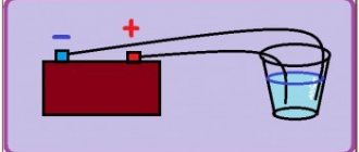
For example, speaker wiring charges are checked using a 3-volt battery. To do this, you need to briefly touch the wires connected to the battery to the speaker terminals.
If the cone in the speaker begins to move outward, this will mean that the positive terminal of the speaker is connected to the positive terminal of the battery, and the negative terminal to the negative terminal. If the diffuser moves inward, the polarity is reversed: the positive terminal is connected to the minus, and the negative terminal to the plus.
If you need to connect a DC power supply or battery, but there are no polarity markings on them, and you don’t have a multimeter at hand, plus and minus can be determined by “folk” methods using improvised materials.
The easiest way to determine polarity that you can use at home is to use potatoes. To do this, you need to take one raw potato tuber and cut it in half. After this, two wires (preferably of different colors or with any other distinctive sign) with their bare ends are stuck into a cut of potato at a distance of 1-2 centimeters from each other.
The other ends of the wires are connected to the constant current source being tested, and the device is turned on (if it is a battery, then after connecting the wires, nothing else needs to be done) for 15-20 minutes. After this time, a light green spot will form on the potato cut around one of the wires, which will be a sign of a positive charge on the wire.
Wire colors in electrical wiring
The color identification scheme is convenient not only for installation. As a rule, different contractors install and operate electrical wiring. Compliance with standards prevents errors during repair work and in the modernization process.
Something to remember! Domestic standards have changed several times over the past decades. Currently, the markings discussed above are used.
Color of zero working and zero protective wires
The color options for the shells will help you recognize the intended purpose of the conductors:
- blue – working zero;
- transverse or longitudinal combinations of yellow and green stripes - protective zero;
- main blue with a change to a combination of yellow and green stripes at the junctions - combined working and protective zero.
Checking the correct connection
Unfortunately, not all electricians strictly follow the standards and make mistakes in choosing a conductor when making connections. Therefore, when hanging a chandelier, installing a socket or other electrical installation device, it is better to additionally check whether the insulation of each core corresponds to its purpose.
Mandatory checking of the neutral or phase is dictated by safety standards and the instinct of self-preservation: if you accidentally mix up the contacts during installation, you can get an unpleasant injury - an electrical burn
For identification, installers use two methods: the first is checking with an indicator screwdriver, the second is using a tester or multimeter. The phase is usually determined with a screwdriver, and neutral and zero are determined with measuring instruments.
How to use the indicator?
Even such simple devices as indicator screwdrivers are different. Some of them are equipped with a small button, others are triggered automatically when a metal rod and a current-carrying conductor or contact are connected.
But all models without exception have a built-in LED that lights up under voltage.
The indicator screwdriver is preferred by amateurs who do not have special qualifications. Professional electricians value accuracy, so they always have a tester with them.
A screwdriver is a convenient tool for identifying the phase conductor. To find out whether the wire is working, use the metal blade of a screwdriver to gently touch the exposed wire.
If the LED lights up, the wire is energized. The absence of a signal indicates that it is ground or zero.
When using the indicator, you must adhere to the safety rules. Even if the screwdriver handle is insulated, it is recommended to wear protective gloves (with a rubberized inner layer), as when working with electricians in general.
The verification procedure is performed with one hand, therefore, the other is free. It is better to also use it - for example, to fix wires. But it is strictly forbidden to touch the exposed parts of conductors or metal objects located nearby (pipes, fittings) with your second hand.
Rules for using the tester
An electrician's kit always includes a tester or multimeter. He has to work with the connection of conductors in electrical installations indoors and when assembling an electrical panel. If the wiring was installed a long time ago, marking the wires by color can be neglected.
Even if the insulation colors seem to be consistent, it is not a fact that they are connected according to all the rules.
Using the tester, you can find out not only the likelihood of connecting conductors to the electrical network, but also some parameters: current, resistance, voltage. Using a multimeter you can test diodes, check transistors, determine inductance
Before taking measurements, you should study the instructions that accompany all measuring instruments.
The procedure is approximately as follows:
- we set a value that is obviously higher than the expected voltage, for example, 260 V;
- connect the probes to the required sockets;
- we touch two conductors with probes - presumably phase and neutral;
- repeat the procedure with another pair of conductors.
The combination of phase-zero cores should produce a result close to 220 V. It will always be higher than the phase-ground pair.
There are both digital, modern instruments on sale, as well as outdated ones, with arrows and value scales. It is more convenient to use digital ones. Before installing electrical devices yourself, we recommend learning how to use either an indicator screwdriver or a multimeter - you should not rely only on the color of the wires.
How to determine ground, zero and phase on wires if there are no markings
It is more difficult to determine in practice than in theory. Not all manufacturers comply with the standards. Therefore, when laying a two-phase 220 V network with grounding, you have to use a VVG cable with blue, brown and red colors. Combinations may be different, but without complying with regulatory requirements.
For your information. In old wiring from “Soviet times” there is no color marking. Identical white (gray) shells do not allow the purpose and correspondence of the lines to be known by simple visual inspection.
To avoid problems, it is recommended to carry out installation work using the same type of cable products. When color coding is not available, it should be created at the joints using insulating tape or heat shrink tubing. The latter option is preferable, as it is designed to maintain integrity for a long time.
Below are methods for determining phase and neutral wires with the advantages and disadvantages of each option. In any case, first clarify the network parameters. In old houses, for example, a two-wire connection scheme with a single working and grounding conductor is often used.
The figure shows a modern network with separate grounding and working zero connections. It is possible to connect three- and single-phase loads.
Determining the phase using an indicator screwdriver
Touching the tip of such a device to the phase wire closes the current circuit. This is accompanied by the warning lamp or LED lighting up. A built-in resistor limits the current to a safe level.
Advantages of the indicator:
- minimum cost;
- compactness;
- reliability;
- durability;
- autonomy;
- good protection from adverse external influences.
The disadvantage is the limited measurement accuracy. Under certain conditions, false positives cannot be ruled out.
Determination of ground, zero and phase using a test lamp
To reproduce this technology, you need to prepare a simple design. An incandescent lamp designed for the appropriate mains voltage is screwed into a standard socket. Connect wires of sufficient length to perform work operations in a specific location.
Next, connect one of the wires to the known zero line. Others sequentially check other cable cores. Lighting of the lamp indicates the presence of a phase.
Using a measuring device
When checking a 220 V household network, you do not need to know how to determine the polarity. The power supply is organized using alternating current, so set the multimeter switch to the appropriate position. Touching the phase-zero (phase-ground) wires with the probes is accompanied by an indication of the corresponding voltage (≈220 V). The potential difference between the neutral conductor and ground is minimal.
For your information. When checking an old two-wire circuit, one of the probes touches the reinforcement in a concrete slab, a radiator of a heating system, or another grounded element of a building structure.
When switching to constant voltage, the multimeter will show where the plus and minus are. In the absence of reliable information about the electrical parameters in the circuit, they begin with the maximum measurement range with a sequential transition to smaller values with insufficient accuracy.
Such a “device” is useful for testing DC circuits in the absence of specialized measuring instruments. Bubbles near the negative wire are the release of hydrogen during the electrolysis reaction. The area near the plus will take on a greenish tint after a few minutes.
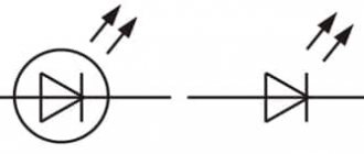
Using LED
You can create a control device with your own hands by analogy with an indicator screwdriver. Instead of a light bulb, install AL 307 or another LED with similar characteristics. A 100-120 kOhm resistor with a power of 1-2 W is added in series to the circuit.
Normative base
The main document describing the requirements for the installation of electrical networks is GOST R 50462–2009, which is based on the IEC 60446:2007 standard. It sets out the rules that the color marking of wires must comply with. They concern manufacturers of cable products, construction and operating organizations whose activities are related to the installation of electrical networks.
Extended installation requirements are contained in the Electrical Installation Regulations. They contain the recommended connection procedure, with reference to GOST-R in paragraphs regarding color gradations.