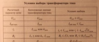
Instrument current transformers 6-10 kV are used in reclosers (RPS), commercial metering points (PKU), CSO cameras - wherever electricity metering or current control is required to protect the line from overload.
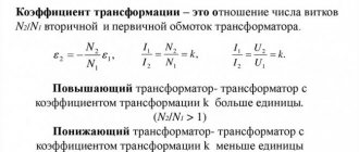
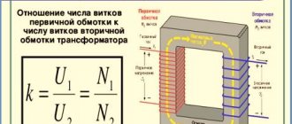
One of the main parameters of a current transformer (CT) is the transformation ratio, which is most often designated 10/5, 30/5, 150/5 or similar. Let's try to figure out what this means and how to choose the correct transformation ratio of the current transformer.
Important! The current transformer is step-up in nature, so its secondary winding must always be short-circuited through an ammeter or simply with a jumper. Otherwise it will burn out or shock someone.
Why are current transformers needed?
Electricians familiar with ~220 V electrical equipment may notice that residential electricity meters are connected directly to the line without the use of current transformers. However, already in three-phase networks, transformer connection is more common than direct connection. In the circuits of PKU and 6-10 kV distribution devices, all measuring devices are connected through current transformers.
The current transformer is designed to reduce the magnitude of the measured current and bring it to the standard range. As a rule, the current is converted to a standard value of 5 A (less often - 1 A or 10 A).
Another purpose of current transformers is to create galvanic isolation between the measured and measuring circuits.
Calculation and selection of measuring CTs
11. Calculation and selection of measuring CTs
Table of contents
11.1 Selection of measuring current transformers, cross-section of cable cores. 3
11.1.1 Measuring current transformers. 3
11.1.2. Methodology for selecting current transformers. 3
11.1.3. Calculation of CT transformation ratio. 3
11.1.4. Checking the choice of CT transformation ratio.. 4
11.2. Calculation of CT secondary load. 4
Appendix 11.1. 7
11.1 Selection of measuring current transformers, cross-section of cable cores
11.1.1 Current transformers
The project describes the general principle for selecting current transformers (CTs), and provides methods and algorithms for calculating CT parameters.
Current transformers used for commercial metering of electricity must be included in the state register of measuring instruments and have a valid certificate (mark in the passport) of verification of measuring instruments.
Current transformers are selected according to rated voltage, primary and secondary currents, type of installation, design, accuracy class.
To connect estimated electricity meters, current transformers with an accuracy class of no more than 0.5S are used.
CT installation is carried out on connections with voltage class 0.4 kV.
The PUE (Chapter 1.5 “Electricity metering”) is used as the main regulatory documents regulating the requirements for the placement of CTs and their parameters.
11.1.2. Methodology for selecting current transformers.
Choice of CT design.
Taking into account the design features of low voltage assemblies and the location of current-carrying busbars, it is necessary to use busbar current transformers of the TShP-0.66, TSh-0.66 type, and reference current transformers of the TOP-0.66, T-0.66 type.
11.1.3. Calculation of CT transformation ratio.
The transformation ratio for each point must be selected taking into account the minimum and maximum primary currents on operating days (summer minimum and winter maximum) or data on the connected power of the subscriber, or fuse settings or the installed power of the power transformer (for organizing technical accounting on TP beams). The maximum primary current of the CT is calculated using the formula:
, A
The minimum current is assumed to be 15% of the maximum:
, A
According to the PUE (clause 1.5.17), the use of current transformers with an overestimated transformation ratio is allowed if, at the maximum load of the connection, the current in the secondary winding of the current transformer is at least 40% of the rated current of the meter, and at a minimum operating load - at least 5%. The choice of CT consists of selecting a CT with a rated primary current that satisfies the condition:
11.1.4. Checking the choice of CT transformation ratio
The selected TT coefficients are checked for compliance with clause 1.5.17 of the PUE. When using electric meters of the type with Inom meter = 5 A, the following inequalities must be satisfied:
; .
Current transformers must be installed type TShP-0.66, or TSh-0.66, with an accuracy class of 0.5S, with a rated secondary load of 5 VA.
The calculated connection currents and selected transformation ratios are given in Appendix 11.1. table 11.1.
11.2. Calculation of CT secondary load.
To ensure that the CT error does not exceed the permissible value for a given accuracy class, the load of the secondary windings of instrument transformers in accordance with GOST 7746 must meet the following requirements: “for transformers with rated secondary loads 1; 2; 2.5; 3; 5 and 10 VA lower limit of secondary loads - 0.8; 1.25; 1.5; 1.75; 3.75 and 3.75 VA respectively.” For CTs with rated secondary loads above 10 W, the secondary load must be at least 25% of the rated load and must not exceed the rated load specified in the catalogs.
The project provides for the use of current transformers of the TShP -0.66 and T-0.66 types. The CT accuracy class is 0.5S, the rated secondary load is 5 VA and the rated secondary current is 5 A. In accordance with the requirements of GOST 7746, the calculated value of the CT secondary load must be in the range: 3.75 VA ... 5 VA (0.15 Ohm ... 0.2 Ohm).
According to GOST 7746, the rated secondary load is the total resistance of the external secondary circuit of the current transformer, which has a power factor of cos φ = 0.8, at which the accuracy class of the current transformer is guaranteed.
The current transformer load consists of the following elements: the resistance of the wires connecting the electric energy meter to the current transformers; resistance of devices included in the current transformer circuit; transition resistance in contact connections.
The external load on the current transformer is determined taking into account the current transformer connection diagram, catalog data for meters and calculated data on the length of the CT secondary circuits given in the cable log.
When calculating the external load of a current transformer, for simplicity, it is assumed that all impedances have the same angles, i.e., they can be added arithmetically. This assumption is acceptable since the error introduced by this is usually small and goes towards the additional margin.
The secondary load of current transformers is determined by the formula,
, Where
— the transition resistance in the contacts is assumed to be 0.05 Ohm;
— resistance of the wires, Ohm (in the case of connecting current transformers with a star in the test terminal box, increase the resistance by 2 times);
— device resistance, Ohm
When selecting current transformers, the following condition must be met:
,
where is the rated load capacity of the current transformer in the selected accuracy class.
The resistance of the wires for the connection circuit of the meter and CT according to the “star” circuit is determined by the formula:
,
where is the length of the wire, m;
— specific conductivity, Ohm/m;
— cross-section of the wire or cable core;
The resistance of the meter is determined from the catalog for the corresponding equipment directly or by recalculation using the data on power consumption and current available in the catalog according to the formula,
,
where is the power, VA, consumed by the device at current I, A.
For the types of meters considered in the project, the power consumed by each current circuit does not exceed 0.1 VA, therefore = 0.004 Ohm.
Load calculations for the secondary measuring circuits of current transformers are given in Appendix 11.1., Table 11.2.
Table 11.1
Selecting the transformation ratio and checking the selected CT transformation ratio at connections in accordance with clause 1.5.17 of the PUE. Data on connected power, permitted one-time power, operating currents are taken on the basis of materials from a pre-design survey of the facility.
| Name of connection | Entry 1 | Input 2 |
| TT type | T-0.66 | T-0.66 |
| U nom, kV | 0,4 | 0,4 |
| Smax, kVA (Imax*√3*Unom) | Data on one-time capacity (permission to connect) is not provided. The transformation coefficient was selected based on a visual inspection of the existing metering unit (TT) and a single-line diagram | |
| — | — | |
| Connection Imax, A (Imax=Smax/(√3*Unom) | — | — |
| Connection Imin (0.15*Imax), A | — | — |
| Rated primary current I(1)CT from the rated series. Selected based on the condition I(1)tm ≤ Imax | 200 | 50 |
| Imax as a percentage of the rated current of the CT, % | — | — |
| Imin as a percentage of the rated current of the CT, % | — | — |
| Rated secondary current CT I(2)CT, A | 5 | 5 |
| CHP transformation coefficient | 40 | 10 |
| Checking for compliance with clause 1.5.17 of the PUE (Imax/Ktt>0.4*Inom count; Inom count=5 A) | — | — |
| Checking for compliance with clause 1.5.17 of the PUE (Imin/Ktt>0.05*Inom count; Inom count=5 A) | — | — |
| The selected primary rated currents and CT transformation ratios correspond to clause 1.5.17 PUE, YES/NO | — | — |
Table 11.2
Calculation of loads of secondary measuring circuits of current transformers IIC.
| Name of feeder 0.4 kV | Entry 1 | Input 2 |
| TT type | T-0.66 | T-0.66 |
| Rated secondary current of CT, A | 5 | 5 |
| Accuracy class | 0.5S | 0.5S |
| Rated secondary load of CT, VA | 5 | 5 |
| Minimum CT secondary load at which the accuracy class of the current transformer is guaranteed, VA | 3,75 | 3,75 |
| Nominal resistance of the secondary winding of the CT, Ohm | 0,2 | 0,2 |
| Counter resistance in current circuits, Ohm | 0,004 | 0,004 |
| Contact resistance in current circuits, Ohm | 0,1 | 0,1 |
| Conductor cross-section (material copper), mm2 | 2,5 | 2,5 |
| Conductor length, m. | 7 | 7 |
| Resistance of secondary circuit conductors, Ohm | 0,049 | 0,049 |
| Resistance of secondary circuits, Ohm | 0,153 | 0,153 |
| Rated load of secondary circuits, VA | 3,825 | 3,825 |
| The load of the secondary circuits is less than the rated secondary load of the CT and more than the minimum for the CT, YES/NO | YES | YES |
Get text
How to choose a current transformer
The maximum operating current of the primary winding of the transformer is determined by the power of the power transformer at the step-down substation.
For example, if the power of the substation is 250 kVA, then with a rated line voltage of 10 kV, the current will not exceed 15 A. This means that the transformation ratio of the current transformers must be at least 3 or, as it is often referred to, 15/5. The use of lower rated current transformers may result in secondary current significantly exceeding the specified value of 5 A, which may lead to a significant reduction in measurement accuracy or even failure of the electricity meter.
Thus, the minimum value of the CT transformation ratio is limited by the rated line current.
Are there any restrictions on the transformation ratio on the other hand? Is it possible to use, for example, 100/5 transformers instead of 15/5 transformers? Yes, such restrictions exist.
If current transformers with a disproportionately large rating are used, the result will be too little current in the secondary winding of the transformer, which the electricity meter will not be able to measure with the required accuracy.
In order not to perform cumbersome mathematical calculations each time, a number of rules have been developed for choosing the CT transformation coefficient. These rules are recorded in the handbook of every power engineer - in the “Rules for the Construction of Electrical Installations” (PUE).
Electrical installation rules allow the use of current transformers with a transformation ratio higher than the rated one. However, such PUE transformers are called “transformers with an overestimated transformation ratio” and their use is limited as follows.
1.5.17. It is allowed to use current transformers with an increased transformation ratio (according to the conditions of electrodynamic and thermal resistance or busbar protection), if at the maximum load of the connection the current in the secondary winding of the current transformer is at least 40% of the rated current of the meter, and at a minimum operating load - at least 5 %.
Since the concept of minimum workload mentioned in the PUE is not very clear, another rule is used:
A current transformer is considered to be overestimated in terms of transformation ratio if, at 25% of the rated connected load (in normal mode), the current in the secondary winding is less than 10% of the rated current of the meter.
Thus, the maximum possible value of the transformation ratio of the current transformers used is limited by the sensitivity of electricity meters.
Selection of current transformers for voltage 6(10) kV
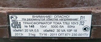
It is required to select current transformers (CTs) of type TOL-SESH-10 for a voltage of 6 kV installed in a cell of type KRU-SESH-61M (JSC Samarsky) to power an electric energy meter of type SET 4TM.03M, connected to the winding of accuracy class 0, 5S (for technical accounting), as well as for connecting a relay protection terminal of the Sirius-21-L-I1 type (RADIUS Avtomatika JSC), according to Fig. 1 and Fig. 2.
A power transformer with a capacity of 2500 kVA is supplied from the designed cell.
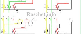
Fig. 1 - Connection diagram of current transformers to the Sirius-21-L-I1 terminal
Fig. 2 - Connection diagram of current transformers to the SET 4TM.03M meter
We must select current transformers based on the following conditions:
1. Rated voltage Uset=6 kV ≤ Unom=10 kV (the condition is met);
2. Rated current Icalc < Inom;
2.1. We calculate the primary rated current:
We first select current transformers for a rated primary current of 300 A (according to the catalog, see table 1) Inom.=300 A > Icalc =240.8 A (the condition is met);
3. In order for the connected devices to operate in the required accuracy class, it is necessary that the connected secondary load Zн does not exceed the rated load for a given accuracy class, and the condition Zн ≤ Z additional must be met.
We calculate the secondary load according to the standard work “Instructions for calculating current transformer loads” “Teploelektroproekt” No. 48082-e.
3.1 Determine the resistance of the meter type SET 4TM.03M:
Where:
- Sapprox. = 0.3 VA – power consumption of the device, according to the catalog for the SET 4TM.03M meter.
- I2nom. = 5 A – rated current of the secondary winding of the current transformer.
3.2 We determine the winding resistance of the current transformers for measurement, calculated from the rated secondary load, equal to 5 VA, according to the catalog on TOL-SESH-10.
3.3 We determine the resistance of the wire (cable) using expression (3) from standard work No. 48082-e, for the connection diagram of current transformers in a full star, assuming that Zn = Zadd:
where: rper=0.05 Ohm – contact resistance for two or three devices and 0.1 Ohm for more devices;
3.4 Determine the cross-section of the cable connecting current transformers of accuracy class 0.5S with a meter type SET 4TM.03M:
Where:
- l – length of the wire (cable) from the current transformer to the installation site of the measuring instruments, m;
- γ – specific conductivity, m/Ohm*mm2 (for copper γ = 57, for aluminum γ = 34.5).
According to the mechanical strength conditions for copper, we accept a cable with a cross-section of 2.5 mm2.
3.5 Determine the actual cable resistance taking into account the accepted one.
3.6 Determine the actual load, in this case the condition Zн < Zadd must be met:
Zn < Zadd.=0.09 Ohm < 0.2 Ohm (the condition is met);
4. Determine the resistance and cable cross-section for the current circuits of the Sirius-21-L-I1 microprocessor terminal, according to Fig. 1.
4.1 Determine the resistance of the Sirius-21-L-I1 microprocessor terminal:
where: Sap. = 0.5 VA – power consumption of the Sirius-21-L-I1 terminal, according to the catalogue.
4.2 We determine the calculated multiplicity for the current cut-off using formula (13) from standard work No. 48082-e:
Where:
- 1.1 – coefficient taking into account the 10% error of the CT when the protection is triggered;
- Is.z.=3000 A – primary protection current;
- I1н – primary rated current of the CT.
Using the maximum multiplicity curve for TOL-SESH-10, we determine the permissible load, based on the calculated multiplicity of 11 at which the error should not be more than 10%. Sadd.=30 VA.
Fig. 3 – Curve of the maximum multiplicity of the secondary winding for protection with accuracy class 5P, 10P and a rated load of 30 VA of a transformer with primary currents of 10...300, 600 A
4.3 We determine the winding resistance of the current transformers for protection - 10P, calculated from the permissible secondary load equal to 30 VA:
4.4 We determine the resistance of the wire (cable) using expression (3) from standard work No. 48082-e, for the connection diagram of current transformers in a full star, assuming that Zn = Zadd:
4.5 Determine the cross-section of the cable connecting current transformers of accuracy class 10P with the Sirius-21-L-I1 terminal:
Where:
- l – length of the wire (cable) from the current transformer to the terminal installation site, m;
- γ – specific conductivity, m/Ohm*mm2 (for copper γ = 57, for aluminum γ = 34.5).
According to the mechanical strength conditions for copper, we accept a cable with a cross-section of 2.5 mm2.
4.6 Determine the actual cable resistance taking into account the accepted one.
4.7 Determine the actual load, provided that Zн < Zadd must be satisfied:
Zn < Zadd.=0.01 Ohm < 1.2 Ohm (the condition is met);
Here I would like to make a small digression, as can be seen from the calculations when using modern equipment in switchgear cells with low power consumption and insignificant cable length, it is possible not to carry out calculations to determine the cable cross-section.
And the cable cross-section should be used according to mechanical strength, according to the PUE section 3.4.4. for current circuits - 2.5 mm2 for copper and 4 mm2 for aluminum;
If, for example, your current transformers are located on the outdoor switchgear, and the measuring equipment is located at a considerable distance from the current transformers, then you must check that the condition Zн ≤ Zadd is met.
5. We check for electrodynamic resistance according to the following conditions:
iу=20.553 kA ≤ ipr.s=80 kA (condition met)
Where:
- iу=20.553 kA – calculated short-circuit shock current;
- ipr.s= 80 kA – dynamic current, selected from the catalog according to table 2 for version 01.
6. Let us determine the limiting current of thermal resistance. In this case, the following condition must be met:
Where:
- Iter. =31.5 kA limiting thermal resistance current, selected from the catalog (see table 2);
- tter=1 sec. - duration of thermal resistance current flow, according to the catalog (see table 2);
- Vk - thermal impulse was calculated early, when choosing a 6 kV power switch.
We select a current transformer of the TOL-SESH-10-01-0.5S/0.5/10P-5/10/30-300/5U2 type and for the current circuits we select a cable of the KVVGEng-4x2.5mm2 brand.
We summarize all calculation and catalog data in Table 3.
Table 3
| No. | Calculation data | Catalog data | Selection condition | Note |
| Current transformer TOL-SESH-10-01-0.5S/0.5/10P-5/10/30-300/5U2 | ||||
| 1 | Uset=6 kV | Unom=10 kV | Uset ≤ Unom | condition is met |
| 2 | Icalc=240.8 A | Inom=300 A | Icalc<Inom | condition is met |
| 3 | Zn=0.09 Ohm | Zadd=0.2 Ohm | Zн ≤ Zadd | For the SET 4TM.03M meter (the condition is met) |
| 4 | Zn=0.01 Ohm | Zadd=1.2 Ohm | Zн ≤ Zadd | For the Sirius-21-L-I1 terminal (the condition is met) |
| 5 | condition is met |
Literature:
1. Standard work “Instructions for calculating the loads of current transformers” “Teploelektroproekt” No. 48082-e 2. Rules for the construction of electrical installations (PUE). Seventh edition. 2008 3. Rozhkova L.D. and Kozulin V.S. Electrical equipment of stations and substations: Textbook for technical schools. − 3rd ed., revised. and additional − M., Energoatomizdat, 1987.
All the best! See you again on the Raschet.info website.