One of the most commonly used electronics components is the timer oscillator. The modern format for the release of its designs is organized in the form of specialized assemblies used in millions of different devices. The most common timer of this type, or, with another name, is the time relay, 555 series of chips, first released and developed by Signetic in 1971.
Due to the lack of competition at that time, it received very high recognition and distribution in electrical device circuits. The characteristics and output signal of the NE555 series of timers (original name) made it possible to use them in the development of generators, modulators, delay systems, various filters, and voltage converters. With the development of digital technology, the microcircuit has not lost its relevance and is already used as its element.
The main task of the 555 timer is to create single or multiple pulses with precise delimitation of time intervals between them.
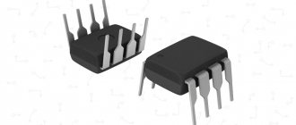
Appearance of the NE555 chip
Features and Specifications
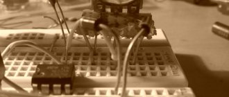
A simple 555-based pulse generator
The most famous feature of the 555 series of chips, which reduces the number of applications for them, is the internal voltage divider. It sets a fixed threshold level for both comparators of the device, which cannot be changed.
The 555 series timer is powered with voltage from 4.5 to 16 volts. Current consumption directly depends on this parameter and ranges from 2 to 15 mA. Output signal characteristics vary among different manufacturers. Basically, its current does not exceed 200 mA.
Temperature conditions also depend on the assembly. Conventional NE555 are designed for operation in the range from 0 to 70°C. Military versions of the timer (historically designated the SE series) allow a wider range - from -55 to 125°C.
During the active period of the timer, there is voltage at the output; it is equal to that arriving at the power bus minus 1.75V. In other cases, this pin has 0.25V, with a total voltage of +5V. The terminology describes these states as high and low signal levels.
The timer is started to generate by a 1/3 volt pulse signal from the device power supply. Its shape is any - sinus or rectangular.
Circuit elements that determine response timing parameters
The response time of the state change is set by the characteristics of the external capacitor between the discharge terminal and ground, as well as the resistance of the two resistors. The first is located on the power bus and connects it to the stop input of the microcircuit. The second is located on the line between the previous one and the discharge contact, but before the previously described capacitance.
Location and assignment of pins
The NE555 and its analogs are primarily available in eight-pin PDIP8, TSSOP, or SOIC packages. The pinout arrangement, regardless of the housing, is standard. The symbolic graphic designation of the timer is a rectangle with the inscription G1 (for a single pulse generator) and GN (for multivibrators).
- General (GND). The first conclusion is regarding the key. Connects to the negative power supply of the device.
- Trigger (TRIG). Applying a low-level pulse to the input of the second comparator leads to the launch and appearance at the output of a high-level signal, the duration of which depends on the rating of the external elements R and C. Possible variations of the input signal are written in the “Montistrator” section.
- Output (OUT). The high level of the output signal is (Upit-1.5V), and the low level is about 0.25V. Switching takes about 0.1 µs.
- Reset (RESET). This input has the highest priority and is able to control the operation of the timer regardless of the voltage on the other pins. To allow startup, it is necessary that a potential of more than 0.7 volts be present on it. For this reason, it is connected through a resistor to the power supply of the circuit. The appearance of a pulse of less than 0.7 volts prohibits the operation of NE555.
- Control (CTRL). As can be seen from the internal structure of the IC, it is directly connected to the voltage divider and, in the absence of external influence, produces 2/3 Upit. By applying a control signal to CTRL, a modulated signal can be obtained at the output. In simple circuits it is connected to an external capacitor.
- Stop (THR). It is the input of the first comparator, the appearance of a voltage on which exceeds 2/3 Upit stops the operation of the trigger and turns the timer output to a low level. In this case, there should be no trigger signal at pin 2, since TRIG has priority over THR (except for KR1006VI1).
- Discharge (DIS). Connected directly to the internal transistor, which is connected according to a common collector circuit. Typically, a timing capacitor is connected to the collector-emitter junction, which discharges while the transistor is in the open state. Less commonly used to increase the load capacity of the timer.
- Power (VCC). Connects to the positive of a 4.5–16V power source.
Advantages and disadvantages
The main advantage of a time relay on a 555 chip is its low price and a huge number of electrical equipment circuits developed and using it.
There are also shortcomings, which, however, have been corrected in the release of microcircuits with a transistor base based on CMOS. When using bipolar ones, at the moment the state of the generating cascade changes to the opposite, a parasitic voltage of up to 400 mA could arise at the terminals. The problem is solved by installing a 0.1 µF polar capacitor between the control contact and the common wire.
Capacitor that reduces the influence of interference on the device
You can also improve the noise immunity of the timer chip. To do this, place a 1 µF non-polar capacitor on the power supply line.
Analogues of the NE555 chip
The 555 chip, the analogue of which in Russia was called KR1006VI1, is an integrated device.
View gallery
Among the working blocks, we should highlight the RS trigger (DD1), comparators (DA1 and DA2), an output amplifier stage based on a push-pull system and a complementary transistor VT3. The purpose of the latter is to reset the time-setting capacitor when using the unit as a generator. The trigger is reset when a logical unit (Jupit/2...Jupit) is applied to the R inputs.
If the trigger is reset, a low voltage reading will be observed at the device output (pin 3) (transistor VT2 is open).
Device operating modes
The main modes of using the 555 series microcircuit are monovibrator, multivibrator and Schmitt trigger.
The first is used to create a one-time signal of a given duration when an input voltage is applied to the start contact of the chip.
The second is for generating many self-oscillating rectangular pulses.
The third, thanks to the memory effect of the previous signal and three options outgoing according to internal logic, in delay systems and digital devices.
One-shot
In this circuit, when a signal of any shape is applied to the second input of the 555 series, a pulse will be generated at its third output. Its duration depends on the characteristics of resistance R and capacitance C. The required duration of the outgoing signal can be calculated using the formula t=1.1*C*R.
Single-shot circuit
Multivibrator
Unlike the previous circuit, the multivibrator does not need an external signal to start continuous generation. All you need to do is connect the power supply. The output is rectangular pulses with a change in state during t2 and with a period of action t1.
Their time is calculated from parameters R1 and R2 using the formulas:
Period and frequency:
To achieve a pulse time greater than the pause time, use a diode connecting the 7th cathode contact of the microcircuit (discharge) with 6 (stop) through its anode.
Multivibrator
Precision Schmitt trigger
The functionality within the 555 series inverting precision switch is provided by the presence of two threshold comparators and an RS flip-flop. The input voltage is divided into three parts, upon reaching the threshold values of which the signal output state of the device changes.
The distinction is made by polarity, and 1/3 of the total supply voltage of either pole is sufficient for switching. At the output, upon receiving a threshold signal at the input, a pulse appears, inverted in polarity relative to the original one. Its level is constant and it lasts exactly the time that the initiating impulse is active.
Simply put, a Schmitt trigger is an inverting monostable with memory of the polarity of the previous signal.
A similar scheme is used in systems where it is necessary to get rid of excess noise and bring its sequences to the required threshold values.
Schmitt trigger circuit with a graph of equalized signal levels
Timer with delayed shutdown on Ne555
My wife and I purchased an anti-mosquito fumigator, and I thought that it was not good that it worked all night, and decided to build a timer on the well-known Ne555.
I assembled the circuit and seemed pleased with it, but I couldn’t get more than 40-50 minutes out of it, and I calmed down, seemingly thinking that this time would be enough for the procedure of killing mosquitoes, but it turned out no, I experimentally determined that at least 2.5 hours were needed (for stable introduction of mosquitoes, in a steep dive). I started studying the Ne555, or rather tinkering with the circuit in the excellent online simulator https://www.falstad.com/circuit/, and discovered that if we apply a voltage from 0 to the supply voltage to the 5th leg of the microcircuit, we can significantly influence timer operation time. Later I looked into the documentation of this wonderful microcircuit and found confirmation of this, the 5th leg was created for this purpose, to influence the timer comparator divider, that is, by applying this or that voltage to the 5th leg of the timer, we can control the shutdown interval. the first thing that came to my mind was to connect a controlled reference voltage source to the fifth leg. But in the simulator it suddenly became clear that this voltage does affect the time interval, but logarithmically, that is, up to 1 volt, it greatly increases this interval, and then with a small scatter. For my purposes, it is necessary to apply a voltage with an amplitude of 0.5 volts, and then the idea came to my mind: what if I apply it through a diode from the output of the microcircuit to the 5th leg of it, but I connected the output of the microcircuit to the anode, well, logically, that’s how it should be work, but nothing happened, that is, the time interval did not change, out of despair I turned the diode the other way around and oh eureka, I got the desired effect on the interval, it became 3.6 times longer, that is, not 40 minutes but 2 hours 20 minutes , this is in the simulator, but practice turned out to be even more generous, the timer turned off after 2 hours 40 minutes, the timer works stably. Now the mosquitoes are also dying, but we see the seller of the fumigator liquid less often, and I still have some money left in my pocket, so I’ll use this extra money to buy this miracle microcircuit. Here is a circuit with an additional diode circuit at the output.
Receive a selection of new homemade products by email. No spam, only useful ideas!
*By filling out the form you agree to the processing of personal data
Scope of application HE555
The capabilities of the microcircuit provide a wide range of equipment in which it is used. Multivibrators based on the 555 series are found in almost all signal generation circuits.
An example is various sound and light warning devices, metal, light, humidity or touch detectors. The timer embedded in the microcircuit allows you to create a time relay to control the operation of various equipment according to periods determined by a person.
Options in the form of a Schmitt trigger are used as filtering converters of noisy signals to give them a regular rectangular shape. Such schemes are also relevant in digital technology, which uses only two types of pulses - its presence and its absence.
Chip 555 practical application
Author: s2. Published in All articles
There is probably no radio amateur who would not use this microcircuit in his practice.
The chip has been around since 1971, when Signetics Corporation released the SE555/NE555 chip called the "Integrated Timer"
Immediately after going on sale, the microcircuit gained wild popularity among both amateurs and professionals. A bunch of articles, descriptions, and diagrams using this device have appeared. Over the past 39 years, almost every self-respecting semiconductor manufacturer has considered it their duty to release their own version of this chip.
But there are no differences in the functionality and location of the pins. All of them are complete analogues of the original Signetics Corporation. New types of circuit solutions are still being found today.
This microcircuit still often surprises me, how by changing the connection of one element in the circuit, the circuit acquires new functionality.
The article contains simple diagrams and examples of the practical application of this microcircuit.
Schmidt trigger.
This is a very simple but effective scheme. The circuit allows, by applying an analog signal to the input, to obtain a pure rectangular signal at the output
— — — — — — — — — — — — — — — — — — — — — — — — — — — — — — — — — — — —
Simple timer.
- NE555 simple timer circuit, video review from user jakson .
— — — — — — — — — — — — — — — — — — — — — — — — — — — — — — — — — — — —
NE555 timer circuit, for more accurate intervals .
— — — — — — — — — — — — — — — — — — — — — — — — — — — — — — — — — — — —
Simple PWM
— — — — — — — — — — — — — — — — — — — — — — — — — — — — — — — — — — — —
Twilight Switch.
— — — — — — — — — — — — — — — — — — — — — — — — — — — — — — — — — — — —
Control your device with one button.
- A version of such a scheme is in this blog.
— — — — — — — — — — — — — — — — — — — — — — — — — — — — — — — — — — — —
A similar circuit for controlling one button on the CD4013 chip (analogous to 561TM2)
— — — — — — — — — — — — — — — — — — — — — — — — — — — — — — — — — — — —
Humidity sensor (indicator).
— — — — — — — — — — — — — — — — — — — — — — — — — — — — — — — — — — — —
Water level control.
Two liquid level sensors can be used to monitor the amount of water in the tank. One sensor reports that there is a small amount of water in the tank, and the second that the tank is full. With a little modification of the circuit, the output signals of the circuit can be connected to more serious loads :).
— — — — — — — — — — — — — — — — — — — — — — — — — — — — — — — — — — — —
ON/OFF sensor.
— — — — — — — — — — — — — — — — — — — — — — — — — — — — — — — — — — — —
Circuit for turning on LED backlight from autonomous power supply, for 10-30 seconds.
One application option is built into the front door near the keyhole.
The backlight is turned on by pressing a button on the door handle - as a result, there will be no problems with opening the lock in the absence of natural or artificial light.
— — — — — — — — — — — — — — — — — — — — — — — — — — — — — — — — — — — —
Combination lock on timer NE555.
I have not yet seen a similar development of a combination lock on the NE555 timer on the Internet, so this development is dedicated to all lovers of this wonderful microcircuit. A circuit based on the NE555 chip in the form of a combination lock for a door or safe can be easily implemented using this timer. I also know that the 555 works normally at low temperatures (if it is to be used outdoors) and has a wider supply voltage range of up to 16V. The reliability of the microcircuit is beyond doubt.
Domestic and foreign manufacturers
The 555 series timer chip is so popular that its analogues are manufactured by almost all well-known brands in the microelectronics industry. Moreover, they are geographically located not only in the USA, but also in other countries of the world. Among them: Texas Instrument, Sanyo, RCA, Raytheon, NTE Silvania, National, Motorola, Maxim, Lithic Systems, Intersil, Harris, Fairchild, Exar ECG Phillips and many others.
Often the series number from competitors contains a reference to the original NE555. There are markings NE555N, HE555P or the like.
Russian KR1006VI1
The timer is also produced in Russia, marked with the KR1006VI1 microcircuit with bipolar transistors and KR1441VI1 using CMOS technology. The national version is slightly different from the classic 555 series - in it the stop input has higher priority than the start signal.
How to make a 555 time relay with your own hands
One of the options for getting acquainted with the 555 series timer is to make your own time relay. The scheme is quite simple, considered classic and can be repeated by a specialist of any level.
Sleep timer circuit
The start is made by pressing the SB1 toggle switch. The duration is adjusted by resistor R2. In the diagram presented, the average operating time is within 6 seconds. To increase it, without changing the characteristics of R2, increase the capacitance of C1.
If a daily cycle of operation is required, then a 1600 µF capacitor will be needed. If the device will be used in conditions close to reality, the number of farads is changed to a more suitable one for the required operating time. The calculation is made according to the formula: T=C1*R2, where C1 is the capacitance of the corresponding capacitor in the circuit, R2 is the average resistance of the megohm trimming resistor.
A more accurate calibration of the action time will be established during use of the variable resistor R2.
A little about the numbering of the used contacts of the 555 series microcircuit, that is, its pinout:
- “Ground” (GND) – power supply minus.
- “Trigger” – a pulse is sent to the contact, starting the timer. Initiated by pressing the toggle switch.
- “Output” – while the timer is active, an outgoing signal is generated at the contact. Its voltage is equal to Vsupply-1.7V, through the limiting resistor R3 allows you to open the base of the transistor VT1. In turn, the semiconductor amplifier begins to pass voltage to the starting relay K1, which already switches the current to the consumer. Diode VD1 in the circuit prevents the surge of parasitic currents during activation.
- “Reset” – when a negative signal is applied, the timer is set to 0 and stopped. To prevent this from happening, the circuit supplies the positive power pole through a resistance to this contact.
- “Control” (Control Voltage) - for such a simple device, this input of the microcircuit is connected to ground through a capacitor. This design increases the noise immunity of the entire assembly.
- “Stop” (Threshold) - in the circuit, the contact is simply connected to the positive pole of the power supply. In more complex systems, briefly shorting it to minus will stop the timer.
- “Discharge” – the contact is designed to connect the 555 microcircuit with a capacitance that specifies the time interval.
- “Power” (VCC) is the plus voltage of the circuit.