It is in every computer, laptop and set-top box. It does not affect your frame rate or Bitcoin mining. It doesn't have billions of transistors, and it doesn't use the latest semiconductor processes. Sound boring? Not at all! Without this thing, our computers would do absolutely nothing.
PSUs, aka power supply units (English PSU, Power Supply Units), do not blow up the headlines like the latest processors, but they are interesting technologies that deserve our attention. So put on your white coats, masks, gloves and let's start opening up our humble little guy - the power supply, let's take it apart and look at what each of its organs does.
And yes, quite recently we figured out how to choose the right power supply. Recommended reading.
What is it and what is it eaten with?
Many computer components have names that require a bit of technical knowledge to understand what they are and why (for example, a solid-state drive), but in the case of a power supply, everything is pretty obvious. This is the unit that provides power.
But we cannot put an end to this, proudly declaring “the article is ready.” Our series of articles is devoted to the internal structure, and on the operating table we have a test subject - the Cooler Master G650M. This is a fairly typical representative, with characteristics similar to dozens of other models, but it has one feature that is not found in all power supplies.
Official photo of the Cooler Master power supply.
This is a standard size power supply that fits the ATX 12V v2.31 form factor, making it suitable for many computer cases.
There are other form factors - for example, for small cases, or completely unique ones upon special order. Not every block corresponds to the exact dimensions established by standard form factors - they may be the same width and height, but differ in length.
This power supply from Cisco is specially designed for server racks
PSU markings usually indicate their main parameter - the maximum power provided. In the case of our Cooler Master, this is 650 W. Later we will talk about what this actually means, but for now we will just note that there are also less powerful power supplies, since not all computers require exactly that much, and some need even an order of magnitude less. But still, most desktop computers are provided with power in the range from 400 to 600 W.
Power supplies like ours are assembled in rectangular, often unpainted, metal cases, which is why they are quite heavy.
Laptops almost always have an external power supply, in a plastic case, but its internals are very similar to what we will see in the power supply we are considering. Photo source nix.ru
Most typical power supplies are equipped with a power switch and a cooler for active thermal regulation, although not all power supplies need it. And not all of them have a ventilation grill - in server versions, in particular, this is rare.
Well, as you can see in the photo above, we are already armed with a screwdriver and are ready to start opening our copy.
Nice bonuses
One of the most pleasant “features” of modern power supplies is the modular design: some of the wires (and sometimes all the wires) have connectors at both ends, allowing you to remove unnecessary and unused “braids” from the system unit: it is both more aesthetically pleasing and it is more convenient to lay cables inside the PC , and less resistance to air flow in the housing.
Of course, you have to pay extra for this feature, albeit a little. If you are assembling a computer and your budget is very limited, you can not bother with “modulars” and just take an inexpensive, high-quality model with “built-in” wires, and you will always find somewhere to invest the extra 500-600 rubles.
A little theory
But before we start digging into the internals, let's ask ourselves, is a power supply really that necessary? Why can't you plug your computer directly into a power outlet? The answer is that computer components are designed for a completely different voltage than the mains voltage.
The graph below shows what the grid electricity should be (US = blue and green curves; UK = red curve). The X axis represents time in milliseconds, and the Y axis represents voltage in volts. The easiest way to understand what voltage is is by looking at the energy difference between two points.
If a voltage is applied to a conductor (such as a metal wire), the difference in energy will cause electrons in the conductor material to flow from a higher energy level to a lower one. Electrons are the constituent atoms that make up a conductor, and metals have many electrons that can move freely. This flow of electrons is called current and is measured in amperes.
A good analogy is with a garden hose: voltage is akin to the pressure you use, and water flow is akin to current. Any restrictions or obstacles in the hose are essentially like electrical resistance.
We see that the electricity in the network varies over time, which is why it is called alternating current voltage (AC, alternating current). In the US, line voltage varies 60 times per second, peaking at 340 V or 170 V, depending on location and connection method. In the UK the peak voltages are lower and the frequency of these fluctuations is also slightly different. Most countries have similar mains voltage standards, with only a few countries having lower or higher peak voltages.
The need for a power supply is that computers do not work with alternating current: they need a constant voltage that never changes, and also much lower. On the same graph it will look something like this:
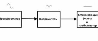
But a modern computer requires not one constant voltage, but four: +12 volts, -12 volts, +5 volts and +3.3 volts. And since these values do not change, such a current is called constant (DC, direct current). Converting current from AC to DC (so-called rectification) is one of the main functions of the power supply. It's time to open it up and see how he does it!
Converting current from AC to DC is one of the main functions of PSU. It's time to see how he does it!
Here we must warn you that the power supply contains elements that accumulate electricity, including deadly electricity.
Therefore, disassembling the PSU is potentially dangerous. Official photo of the Cooler Master power supply.
The principle of operation of this power supply is similar to many others, and although the markings on various parts inside will be different, this does not make any fundamental differences.
The power cord connector is in the top left corner of the photo, and the current essentially flows clockwise until it reaches the output of the power supply (bundle of colored wires, bottom left corner).
Photo source
techspot.com
If we turn the board over, we can see that compared to the motherboard, the conductors and connections on it are wider and more massive - this is because they are designed to handle higher currents. Also, a wide stripe in the middle catches your eye, like a river flowing across the plain.
This again suggests that all power supplies have two clearly separated nodes: primary and secondary. The first is to adjust the input voltage so that it can be effectively stepped down; the second is all the settings for the already rectified and reduced voltage.
Passive cooling
For fans of deathly silence, there are special fanless models that do not make any sounds at all (if, of course, the manufacturer has installed normal chokes). All of them are usually obscenely expensive due to 80+ Platinum / Titanium certification (and without such efficiency, passive cooling is difficult to obtain).
Thanks to the resource Overclockers.ru for the picture.
An example is the 500-W Chieftec PGS-500C. The price is an impressive 10 and a half thousand rubles. For about the same money, for example, you can buy an 850-Watt TT Moscow with “gold” certification and a completely silent cooler or a 1000-Watt TT Volga with similar characteristics in terms of efficiency and noise.
You can only hear it in a remote crypt, but ordinary people cannot understand these passive people 
Filtration
The first thing the power supply does with mains electricity is not rectification or reduction, but equalization of the input voltage. Since our homes, offices and businesses have many electrical devices and appliances that constantly turn on and off, as well as emitting electromagnetic interference, alternating current in the network is often “lumpy” and with random surges and drops (the frequency is also not constant). Not only does this make it difficult for the power supply to carry out conversions, but it can damage some of the components inside it.
Our power supply has two stages of so-called input filters (transient filter), the first of which is built directly at the input using three capacitors. It performs a role similar to that of a speed bump on the road - only instead of speed, this filter dampens sudden surges in input voltage.
Photo source techspot.com
The second filter stage is more complex, but essentially does the same thing.
The yellow bricks are again capacitors, but the green rings wrapped in copper wire are inductive coils (although when used in this way they are usually called chokes). The coils accumulate electrical energy in a magnetic field, but the energy is not lost and is smoothly returned due to self-induction. Thus, a suddenly appearing high pulse (jump) is absorbed by the magnetic field of the inductor in order to give an even voltage at the output without any jumps.
The two small blue disks are another representative of the capacitor variety, and just below them (green, with long legs covered with black insulators) is a metal oxide varistor (MOV). They are also used to protect against input voltage surges. You can read more about the different types of input filters here.
Photo source techspot.com
From this power supply unit you can often determine how much the manufacturer has saved, or what budget class the device belongs to. Cheaper ones will have simplified input filtering, and the cheapest ones will not have it at all (avoid these!).
Now that the tension has been leveled and combed, he is allowed to move on - in fact, to transformation.
Conversion
As we said, the power supply needs to change the AC voltage, which in American outlets is usually around 120 volts (technically, this is 120 volts rms, but we won’t break our tongue like that), giving the output a constant voltage of 12, 5 and 3. 3 volts.
The first step is to convert AC to DC, and our unit uses a bridge rectifier for this. In the photo below it is a flat black element glued to the radiator.
Photo source techspot.com
This is another place where the power supply manufacturer can cut costs, since cheaper rectifiers perform worse (eg run hotter). Now, if the peak input voltage is 170 V (which is the case for a 120 V network), then after passing through the rectifier bridge, it will become 170 V, but already DC.
In this form, it enters the next stage, and in our block it is an active power factor correction module (APFC or Active PFC, Active Power Factor Correction converter). This unit also stabilizes the voltage, smoothing out “dips” due to storage capacitors; In addition, it protects against output power surges.
Passive correctors (PPFC or Passive PFC) do essentially the same job. They are less efficient, but good for low-power power supplies.
Photo source techspot.com
The APFC in the photo above is represented by a pair of large cylinders on the left - these are capacitors that accumulate equalized current before sending it further along the chain of processes in our power supply.
Behind the APFC there is a PWM, pulse width modulator (PWM, Pulse Width Modulator). Its purpose is to convert direct current back to alternating current using several fast-switching field-effect transistors. This needs to be done because in the next step a step-down transformer awaits us. These devices, based on electromagnetic induction, consist of two windings with different numbers of turns on the metal core needed to step down the voltage, and operate transformers with alternating current only.
The frequency of the AC current (the rate at which it changes; in Hertz, Hz) greatly affects the efficiency of the transformer - the higher the better, so the frequency of the original 50/60 Hz supply increases by about a thousand times. And the more efficient the transformer, the smaller its size. This type of device that uses these ultra-fast DC frequencies is called a Switched Mode Power Supply (SMPS).
In the photo below you can see 3 transformers - the largest one has 12 volts at its only output, and the smaller one has 5 volts (we'll talk about it a little later). In other power supplies you can find one large transformer for all voltages at once, that is, with several outputs. And the smallest transformer is designed to protect PWM transistors and suppress its interference.
| Photo source techspot.com
You can implement in different ways obtaining the necessary voltages, PWM protection, and so on. It all depends on the budget segment and the power of the device. However, everyone equally needs to remove the voltage from the transformers and straighten them again.
In the photo below we see an aluminum heatsink for the low-voltage diodes that perform this rectification. And also, specifically in this PSU, we see a small additional board in the center of the photo - this is a node of voltage regulation modules (VRM, Voltage Regulation Modules), providing outputs of 5 and 3.3 volts.
Photo source techspot.com
And here we should talk about what pulsation is.
In an ideal world, with ideal power supplies, alternating current will be converted into absolutely smooth, without the slightest fluctuation, direct current. In reality, such 100% accuracy is not achieved, and the DC voltage has, albeit minor, fluctuations.
This effect is called ripple voltage, and in our power supplies we like to keep it as low as possible. Cooler Master does not provide information about the ripple voltage value in the specification for our experimental PSU, so we resorted to third-party testing results. One such analysis was performed by JonnyGuru.com and they found that the maximum ripple voltage of the +12V output was 0.042V (42 millivolts).
The graph below shows the deviation of the actual voltage received (blue curve; its shape, of course, is not such an ideal sine wave - after all, the ripple itself is not constant) from the required flat voltage of +12 V DC (red straight).
This deviation is largely the responsibility of the capacitors throughout the PSU. Low-quality, cheap capacitors lead to an increase in this unnecessary ripple. If it is too large, then some electronic components of the computer that are most sensitive to power quality may begin to work unstable. Fortunately, in our example, 40-plus millivolts is normal. Not great, but not bad either.
But obtaining acceptable output voltages is not the end of the matter.
It is necessary to ensure control of the outputs so that the power at each of them is always full and stable, regardless of the power of the loads at other outputs. Photo source techspot.com
The chip you see in this photo is called a supervisor and it makes sure that the pins do not have too high or low voltage and current. It works simply - it simply turns off the power supply when such problems occur.
More expensive PSUs can be equipped with a digital signal processor (DSP), which not only monitors voltages, but can also adjust them if necessary, and also send detailed data about the state of the power supply to the computer using it. For the average user, this function is quite controversial, but for servers and workstations it is highly desirable.
Power supplies
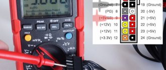
Wiring for ATX power supply connectors (ATX12V) with ratings and color coding of wires:
Contact table of the 24-pin ATX power supply connector (ATX12V) with ratings and color coding of wires
- Comte
- Designation
- Color
- Description
| 1 | 3.3V | Orange | +3.3 VDC |
| 2 | 3.3V | Orange | +3.3 VDC |
| 3 | COM | Black | Earth |
| 4 | 5V | Red | +5 VDC |
| 5 | COM | Black | Earth |
| 6 | 5V | Red | +5 VDC |
| 7 | COM | Black | Earth |
| 8 | PWR_OK | Grey | Power Ok - All voltages are within normal limits. This signal is generated when the power supply is turned on and is used to reset the system board. |
| 9 | 5VSB | Violet | +5 VDC Standby voltage |
| 10 | 12V | Yellow | +12 VDC |
| 11 | 12V | Yellow | +12 VDC |
| 12 | 3.3V | Orange | +3.3 VDC |
| 13 | 3.3V | Orange | +3.3 VDC |
| 14 | -12V | Blue | -12 VDC |
| 15 | COM | Black | Earth |
| 16 | /PS_ON | Green | Power Supply On. To turn on the power supply, you need to short-circuit this contact to ground (with a black wire). |
| 17 | COM | Black | Earth |
| 18 | COM | Black | Earth |
| 19 | COM | Black | Earth |
| 20 | -5V | White | -5 VDC (this voltage is used very rarely, mainly to power old expansion cards.) |
| 21 | +5V | Red | +5 VDC |
| 22 | +5V | Red | +5 VDC |
| 23 | +5V | Red | +5 VDC |
| 24 | COM | Black | Earth |
- a typical 450W power supply circuit with the implementation of active power factor correction (PFC) for modern computers. - a typical diagram of a 300W power supply with notes on the functional purpose of individual parts of the circuit.
— Power supply diagram Alim ATX 250Watt SMEV JM 2002. atx-300p4-pfc.png — Power supply diagram ATX-300P4-PFC (ATX-310T 2.03).
— ATX-P6 power supply diagram. GPS-350EB-101A.pdf - PSU diagram CHIEFTEC TECHNOLOGY 350W GPS-350EB-101A. GPS-350FB-101A.pdf - PSU diagram CHIEFTEC TECHNOLOGY 350W GPS-350FB-101A.
— Chieftec CTG-350-80P, CTG-400-80P, CTG-450-80P and CTG-500-80P ctg-350-500.pdf — Chieftec CTG-350-80P, CTG-400-80P, CTG-450- 80P and CTG-500-80P cft-370_430_460.pdf — Diagram of power supplies Chieftec CFT-370-P12S, CFT-430-P12S, CFT-460-P12S
— Power supply diagram Chieftec 400W iArena GPA-400S8 GPS-500AB-A.pdf — Power supply diagram Chieftec 500W GPS-500AB-A. GPA500S.pdf - PSU diagram CHIEFTEC TECHNOLOGY GPA500S 500W Model GPAxY-ZZ SERIES. cft500-cft560-cft620.pdf - Diagram of power supplies Chieftec CFT-500A-12S, CFT-560A-12S, CFT-620A-12S - Diagram of power supplies Chieftec 550W APS-550S gps-650_cft-650.pdf - Diagram of power supplies Chieftec 650W GPS-650AB-A and Chieftec 650W CFT-650A-12B ctb-650.pdf — Power supply diagram Chieftec 650W CTB-650S ctb-650_no720.pdf — Power supply diagram Chieftec 650W CTB-650S Board marking: NO-720A REV- A1 aps-750.pdf - Diagram of power supplies Chieftec 750W APS-750C ctg-750.pdf - Diagram of power supplies Chieftec 750W CTG-750C cft-600_850.pdf - Diagram of power supplies Chieftec CFT-600-14CS, CFT-650-14CS , CFT-700-14CS, CFT-750-14CS cft-850g.pdf — Power supply diagram Chieftec 850W CFT-850G-DF cft-1000_cft-1200.pdf — Power supply diagram Chieftec 1000W CFT-1000G-DF and Chieftec 1200W CFT -1200G-DF
— NUITEK (COLORS iT) 330U (sg6105) power supply circuit. — NUITEK (COLORS iT) 330U power supply circuit on the SG6105 chip. 350U.pdf - NUITEK (COLORS iT) 350U SCH power supply diagram. 350T.pdf - NUITEK (COLORS iT) 350T power supply diagram. 400U.pdf - NUITEK (COLORS iT) 400U power supply diagram. 500T.pdf - NUITEK (COLORS iT) 500T power supply diagram. 600T.pdf - PSU diagram NUITEK (COLORS iT) ATX12V-13 600T (COLORS-IT - 600T - PSU, 720W, SILENT, ATX)
— PSU circuit Codegen 300w mod. 300X. PUH400W.pdf - PSU diagram CWT Model PUH400W.
— Power supply diagram Dell 145W SA145-3436 Dell-160W-PS-5161-7DS.pdf — Power supply diagram Dell 160W PS-5161-7DS Dell_PS-5231-2DS-LF.pdf — Power supply diagram Dell 230W PS-5231- 2DS-LF (Liteon Electronics L230N-00) Dell_PS-5251-2DFS.pdf - Power supply diagram Dell 250W PS-5251-2DFS Dell_PS-5281-5DF-LF.pdf - Power supply diagram Dell 280W PS-5281-5DF-LF model L280P-01 Dell_PS-6311-2DF2-LF.pdf — Power supply diagram Dell 305W PS-6311-2DF2-LF model L305-00 Dell_L350P-00.pdf — Power supply diagram Dell 350W PS-6351-1DFS model L350P-00 Dell_L350P-00_Parts_List.pdf - List of parts for power supply Dell 350W PS-6351-1DFS model L350P-00 delta-450AA-101A.pdf - Power supply diagram Delta 450W GPS-450AA-101A DTK-PTP-1358.pdf - Power supply diagram DTK PTP-1358. DTK-PTP-1503.pdf - Power supply diagram DTK PTP-1503 150W DTK-PTP-1508.pdf - Power supply diagram DTK PTP-1508 150W DTK-PTP-1568.pdf - Power supply diagram DTK PTP-1568. DTK-PTP-2001.pdf - DTK PTP-2001 200W power supply diagram. DTK-PTP-2005.pdf - DTK PTP-2005 200W power supply diagram.
— Power supply diagram DTK Computer model PTP-2007 (aka MACRON Power Co. model ATX 9912) DTK-PTP-2007.pdf — Power supply diagram DTK PTP-2007 200W. DTK-PTP-2008.pdf - DTK PTP-2008 200W power supply diagram. DTK-PTP-2028.pdf - DTK PTP-2028 230W power supply diagram.
— Power supply circuit DTK PTP-2038 200W. DTK-PTP-2068.pdf - Power supply diagram DTK PTP-2068 200W DTK-PTP-3518.pdf - Power supply diagram DTK Computer model 3518 200W. DTK-PTP-3018.pdf - DTK DTK PTP-3018 230W power supply diagram. DTK-PTP-2538.pdf - Power supply diagram DTK PTP-2538 250W DTK-PTP-2518.pdf - Power supply diagram DTK PTP-2518 250W DTK-PTP-2508.pdf - Power supply diagram DTK PTP-2508 250W DTK- PTP-2505.pdf - Power supply diagram DTK PTP-2505 250W
— EC model 200X power supply circuit.
— Power supply diagram FSP Group Inc. model FSP145-60SP. — Diagram of the standby power supply power supply FSP Group Inc. model ATX-300GTF.
— Diagram of the standby power supply power supply FSP Group Inc. model FSP Epsilon FX 600 GLN.
— Green Tech power supply diagram. model MAV-300W-P4.
— Power supply circuits INWIN IW-P300A2-0 R1.2. IW-ISP300AX.gif - INWIN IW-P300A3-1 Powerman power supply circuits.
The most common malfunction of Inwin power supplies, the diagrams of which are given above, is the failure of the standby voltage generation circuit +5VSB (standby voltage).
As a rule, it is necessary to replace the electrolytic capacitor C34 10uF x 50V and the protective zener diode D14 (6-6.3 V). In the worst case, R54, R9, R37, U3 microcircuit (SG6105 or IW1688 (complete analogue of SG6105)) are added to the faulty elements. For the experiment, I tried installing C34 with a capacity of 22-47 uF - perhaps this will increase the reliability of the duty station.
IP-P550DJ2-0.pdf - diagram of the Powerman IP-P550DJ2-0 power supply (IP-DJ Rev:1.51 board). The standby voltage generation circuit in the document is used in many other models of Power Man power supplies (for many power supplies with a power of 350W and 550W, the differences are only in the ratings of the elements).
- JNC Computer Co. LTD LC-B250ATX JNC_SY-300ATX.pdf - JNC Computer Co. LTD. SY-300ATX power supply diagram
— Power supply circuits Key Mouse Electroniks Co Ltd model PM-230W — Power supply circuits L & C Technology Co. model LC-A250ATX LiteOn_PE-5161-1.pdf - Diagram of LiteOn PE-5161-1 135W power supplies. LiteOn-PA-1201-1.pdf - Diagram of power supplies LiteOn PA-1201-1 200W (complete set of documentation for the power supply) LiteOn_model_PS-5281-7VW.pdf - Diagram of power supplies LiteOn PS-5281-7VW 280W (complete set of documentation for PSU) LiteOn_model_PS-5281-7VR1.pdf - Diagram of power supplies LiteOn PS-5281-7VR1 280W (complete set of documentation for the PSU) LiteOn_model_PS-5281-7VR.pdf - Diagram of power supplies LiteOn PS-5281-7VR 280W (complete set of documentation for BP)
— Circuits of the LWT2005 power supply on the KA7500B and LM339N chip
— PSU diagram M-tech KOB AP4450XA. — PSU diagram MACRON Power Co. model ATX 9912 (aka DTK Computer model PTP-2007)
— PSU diagram Maxpower PX-300W
— PSU circuit Maxpower PC ATX SMPS PX-230W ver.2.03
— Power supply diagrams PowerLink model LP-J2-18 300W.
— Power supply circuits Power Master model LP-8 ver 2.03 230W (AP-5-E v1.1).
— Power supply circuits Power Master model FA-5-2 ver 3.2 250W. microlab350w.pdf - Microlab 350W power supply circuit microlab_400w.pdf - Microlab 400W power supply circuit - Powerlink LPJ2-18 300W power supply circuit
— PSU circuit Powerlink LPK, LPQ
— PSU circuit Power Efficiency Electronic Co LTD model PE-050187 ATX-230.pdf — PSU circuit Rolsen ATX-230
— PSU diagram SevenTeam ST-200HRK
— PSU circuit SevenTeam ST-230WHF 230Watt
— PSU diagram SevenTeam ATX2 V2 hpc-420-302.pdf — PSU diagram Sirtec HighPower HPC-420-302 420W HP-500-G14C.pdf — PSU diagram Sirtec HighPower HP-500-G14C 500W cft-850g-df_141.pdf — Power supply diagram SIRTEC INTERNATIONAL CO. LTD. NO-672S. 850W. Power supplies from the Sirtec HighPower RockSolid line were sold under the CHIEFTEC CFT-850G-DF brand. — Power supply diagrams SHIDO model LP-6100 250W.
— Power supply diagram SUNNY TECHNOLOGIES CO. LTD ATX-230 — Power supply diagram Utiek ATX12V-13 600T — Power supply diagram Wintech PC ATX SMPS model Win-235PE ver.2.03
Exits
All power supplies come with long bundles of wires sticking out from the back. The number of wires and available connectors for powering devices will vary from model to model, but some standard connections should be provided by all power supplies without exception.
Since voltage is the magnitude of the potential difference, each output has two wires: one for the specified voltage (for example, +12 V) and a wire against which the potential difference is measured. This wire is called the ground, "earth", "reference wire" or "common" wire, and these two wires form a loop: from the power supply to the consumer device, and then back to the power supply.
Because some of these closed loops carry small currents, they may share common ground wires.
Official photo of the Cooler Master power supply.
The main required connector is the 24-pin ATX12V v. 2.4, which provides main power via several pins of different voltages, and also has a number of special pins.
Of these special ones, we note only the “+5 standby” pin – standby power supply for the computer. This voltage is always supplied to the motherboard, even when the computer is turned off, provided that it remains plugged in and its power supply is working. The motherboard needs standby power in order to remain active.
Most PSUs also have an additional 8-pin motherboard connector with two +12V lines, and at least one 6 or 8-pin power connector for PCI Express.
The PCI Express slot can handle a maximum of 75W of graphics cards, so this slot provides additional power for modern GPUs.
Our particular power supply in question actually uses two PCI Express power connectors on the same lane for cost reasons. Therefore, if you have a really powerful video card, try to allocate an independent power line for it, do not share it with other devices.
The difference between 6 and 8-pin PCI Express connectors is two additional ground wires. This allows you to increase the current, satisfying the needs of the most power-hungry video cards.
Over the past few years, we have increasingly begun to notice power supplies proudly labeled “modular” (modular PSU). This simply means that they have detachable cables, allowing you to use only the number of cables and connectors you need without connecting anything unnecessary, thereby freeing up space inside the unit.
Photo source nix.ru
Our Cooler Master, like most, uses a fairly simple system for connecting modular cables.
Each connector has one +12V, +5V and +3.3V wire, as well as two ground wires, and depending on what device the cable is connected to, the connector at the other end will use either the corresponding or simplified wiring.
The Serial ATA (SATA) connector pictured above is used to connect power to hard drives, solid-state drives, and peripherals such as DVD drives.
This familiar connector is called intricately: “AMP MATE-N-LOK power connector 1-480424-0”. But everyone simply calls it Molex, despite the fact that this is just the name of the company that developed this connector. It provides one +12V and +5V terminal, and two ground wires.
On output wires, manufacturers can also save money or increase the price by using brighter or softer wires. The cross-section of the wire also plays an important role, since thicker wires have less resistance than thin ones, so they heat up less when current passes through them.
Pinout of the main PSU connector
To carry out repairs, we will also need to know the pinout of the main power connector, it is shown below.
PSU plugs: A – old style (20pin), B – new (24pin)
To start the power supply, you need to connect the green wire (PS_ON#) to any black zero wire. This can be done using a regular jumper. Note that some devices may have color markings that differ from the standard ones; as a rule, unknown manufacturers from the Middle Kingdom are guilty of this.
What to look for when choosing
At the beginning of our article, we said that most power supplies have the value of their maximum power in their name. In simple terms, electrical power is voltage times current (for example, 12 volts x 20 amps = 240 watts). Although this statement is not entirely technically accurate, for our purposes it is satisfactory.
Like most models, our power supply has a nameplate that contains basic information about how much power each voltage line can provide.
Photo source nix.ru
Here we see that the total maximum power of all +12 V lines is 624 W. Adding all the other powers, we end up with 760 W, not 650. What's wrong with that? The simple fact is that the +5 V lines (except for the standby line) and +3.3 V are created through the VRM using one of the +12 V lines.
And of course, all output voltages come from one source: the wall outlet. Thus, a power of 650 W is the maximum that the power supply can provide overall across all lines. That is, if you have a load of 600 W on the +12 V lines, then you have only 50 W left on all other lines. Fortunately, most equipment takes most of its power from 12V lines anyway, so the problem of an incorrectly selected power supply is rare.
To the right of the table with power specifications, there is an “80 Plus Bronze” icon on the nameplate. This is the efficiency rating used by the industry to meet requirements for power supply manufacturers. Efficiency also reflects the amount of total load the power supply can handle.
20%, 50% and 100% – percentage of load in relation to maximum power for standard systems
If our Cooler Master is loaded at exactly half of its maximum power, that is, 325 W, then its expected efficiency will be in the range of 80-85% depending on the network voltage (115/230 V).
This means the actual load of the power supply on the network is from 382 to 406 W. A higher 80 PLUS rating doesn't mean the power supply will give you more power, it's just more energy efficient - it wastes less power in all stages of filtering, rectification and conversion.
Also note that maximum efficiency is achieved between 50 and 100% load. Some manufacturers provide graphs showing what efficiency can be expected from their device at various loads and line voltages.
Official image from Cooler Master.
Efficiency graph for the Cooler Master V1300 Platinum power supply. The vertical scale is efficiency (efficiency), the horizontal scale is % of load relative to maximum power.
Sometimes it is useful to pay attention to this information, especially if you are going to fork out for a kilowatt power supply. If your computer draws close to this power limit, the efficiency of the power supply will be slightly reduced.
You may come across some “single-channel” and “multi-channel” (or combined - equipped with a switch) power supplies. The term "channel" in this case is simply another word for the specific voltage output by the PSU. Our Cooler Master has one 12V channel and various power connectors providing +12V line from this channel. A multi-channel power supply has two or more systems providing 12 volt lines, however there is a big difference in how this is implemented.
Multi-channel power supplies are widely used for servers or data centers for fault tolerance purposes - if one of the channels fails, the system’s functionality will not be affected. For regular computers, multi-channel PSUs may also be offered, but most likely you will encounter pseudo-multi-channel, when the manufacturer simply splits a single channel into two or three supposedly independent channels. For example, our test subject produces up to 52 amps along the +12V line, which is equivalent to 624 W of electricity. A cheap “multi-channel” version of such a power supply will supposedly have two +12 V channels in the specification, but in reality these are only two half-channels, each of which will provide only 26 A (or 312 W).
A good desktop power supply that uses quality components doesn't require multi-channel +12V at all, so don't worry about it!