The traction substation performs the key task of converting electricity in order to supply it to the contact network to power electric transport (ground and underground). This is a separate area of technology, the main function of which is to reduce the voltage value, and, if necessary, to rectify the current if it is intended to operate an installation operating on direct current.
- Scope of use
- Types and their features
- Properties and characteristics of TP
- Criterias of choice
- Recommendations from experts
What is a contact network
Contact network is a set of linear current-carrying, insulating, supporting and supporting elements designed to supply electricity to the substation current collectors. The contact wire is made of chalk and its alloys (copper-cadmium and copper-magnesium) with a cross-section of 65–100 mm2. On auxiliary lines and lines in depots, copper wires with a steel core may be used. The wire must have good electrical conductivity, wear resistance and high strength to allow reliable tension.
The cross-section of contact wires is selected taking into account their cost according to the so-called economic current density from the condition of the optimal ratio between the consumption of non-ferrous metals and losses of electrical energy in the traction network. The hanging height of contact wires on lines under construction or reconstruction must be 6.0 m. A reduction in the hanging height is allowed inside production premises, under bridges and overpasses - up to 4.2 m, in tunnels - up to 3.9 m.
At high current loads of the contact network or when the voltage drop at the end of the section is greater than permissible, reinforcing wires made of copper, aluminum or twisted wire made of steel and aluminum wire are laid parallel to the contact wires to increase strength. At certain intervals these wires are connected to the contact wires.
Catenary suspension is a system for suspending contact wires to supporting structures. Depending on the method of hanging, fastening and maintaining tension, catenary pendants can be simple, chain and polygon. The distance between the points of attachment of the contact wire to the supporting structures is called the catenary span length. For fastening contact wires and supporting structures, various fittings with or without insulation are used.
Traction substation - top view.
Polygon suspension is used when electric transport lines pass under artificial structures, on curved sections, city squares, etc. In this case, the entire suspension and contact wire are located in a horizontal plane. The contact wires of tram lines on straight sections of the track are arranged in a zigzag pattern with a distance from the center line of up to 400 mm for uniform wear of the current collector.
At the intersections of contact wires, air crossings and crosses are installed. They ensure the passage of PS current collectors without contact with the crossed contact wire along special guides. For this purpose, non-contact sections are organized at intersections, which the PS coasts through. Brackets, simple and chain flexible crossbars, beams and ceilings of overpasses, tunnels and other engineering structures are used as supporting devices in the contact networks of trams and trolleybuses. Flexible devices typically use galvanized steel seven-wire rope.
Supporting structures are intended for fastening supporting devices: special supports (reinforced concrete or steel), walls of brick and reinforced concrete buildings, structures of tunnels, bridges and overpasses.
The trolleybus contact network must ensure the movement of the trolleybus in the first and second lanes, and on the approaches to left turns - in the far left lane, provide for the possibility of timely changing lanes of the trolleybus, taking into account the specific road situation. The negative (zero) wire of the trolleybus contact network is located on the right side in the direction of travel.
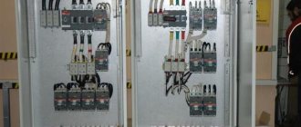
Traction substation control panel.
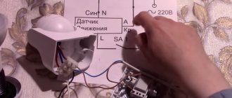
To change the direction of trolleybus movement, switches are installed on the contact network. Traditionally, switches of the trolleybus contact network are controlled similarly to trams, i.e. depending on the presence of traction when approaching the turnout. Modern turnouts are controlled using a radio signal from the driver's cabin. A transmitter (radio transmitting device) and a number of control buttons are installed in the cabin. On the contact network support next to the automatic switch there is a device that receives radio signals and supplies a control impulse to the switch drive, as well as a special traffic light that shows the direction of movement of the trolleybus at the current position of the switch feathers.
If the driver is satisfied with this direction, then he, without performing any actions, passes the arrow and follows the given route. If the driver needs to move the arrow in another direction, he presses a certain button on the control panel and thereby sends a radio signal that activates the arrow drive. Within 1.5-2.0 seconds, the direction of movement is switched, and the trolleybus follows a different path. After the car passes, the switch remains in its new position. Such arrows do not have de-energized elements, so the driver does not need to specifically reduce speed to pass them.
If several automatic switches are installed at one place on the route, then different buttons are used to control them. The radio transmitting device has four channels; to control each arrow at complex intersections, its own channel is determined. Similar arrows operate automatically without driver intervention.
Types of traction substations
Traction substation is primarily divided into two groups:
- Direct current.
- Alternating current.
The first of these options includes equipment designed for 6-220 kV. In this case, power is supplied via overhead and cable power lines. In the case when the voltage is below the threshold of 110 kV, a reduction is required; accordingly, the electricity first goes through the stage of reducing the value of the electrical parameters with the participation of a transformer.
In other situations, the energy is sent directly to the distribution board. device. A multi-type AC traction substation is by and large similar to equipment of this kind operating on direct current, with the only exception being the absence of a converting unit for rectifying the electrical characteristics.
Why is a traction substation needed?
Traction substation of different types is also found in other designs, the division is carried out according to the intended purpose of the transport:
- Equipment for the railway. Available in the following variants:
- Support – can act as a power source for other installations;
- Dead-end – receives electricity from a nearby substation;
- Intermediate - powered by two nearby installations.
- Traction substations for trams and trolleybuses. Equipment of this type also exists in several versions:
- With the need for the participation of service personnel;
- Fully automated;
- TP for trams and trolleybuses, which do not require personnel to operate the equipment and are remote-controlled equipment.
- Installations for the metro. The following types of such equipment are distinguished:
- Traction;
- Decreasing;
- Traction-lowering.
It will be interesting➡ What is a pulse transformer and how to calculate it
In the first case, a traction distribution substation is presented, powered by city power grids. The second of these options involves receiving high current from the traction unit, which is subsequently reduced to a level of 400-230 V, which is sufficient for power and lighting devices.
Transformer substation.
Specifications
Traction substations for trams, metro and trolleybuses and railway transport have a number of parameters according to which the required option is selected. By the way, if we compare them with equipment such as STP pole substations, which are powered by alternating current and are represented exclusively by a dead-end design, the range will be very wide, which makes the choice somewhat difficult.
To navigate a large number of designs, you need to clearly understand what loads will be placed on equipment of this type, according to which the equipment parameters are determined:
- the value of resistance and voltage on the buses where the rectified current is supplied;
- the traction substation of the metro, railway and other electric transport is characterized by internal resistance, as well as the resistance of the suction feeder and smoothing unit; using these values, you can obtain the resistance value of the entire installation by summing them up;
- Metro and Russian Railways traction substations differ in the number of transformers and switchgear used in the design. devices;
- the voltage of the entire installation is a calculated value and is determined from the formulas;
- short circuit power.
For comparison, the defining parameters for equipment such as pole-mounted transformer substations are: total power, as well as high and low voltage values.
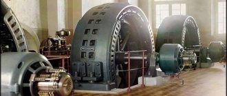
High power traction substation.
Where can it be used
A traction substation is a separate type of equipment that provides a source of electricity for all types of electric vehicles. But for each direction a special type of similar technology is assumed. TPs can be located along the entire length of the road at intervals of 25 to 50 km. The frequency with which a traction substation is installed is determined by several factors, including: the profile of the railway, the size and intended purpose of the vehicle.
Let's watch the video, scope and types of TP:
The main directions that involve the installation of this type of equipment are:
- Railway transport;
- Metropolitan;
- Ground electric transport (trams, trolleybuses).
The traction substation can be represented in different designs, differing in technical characteristics. In this case, the feasibility of installing one or another option is determined by the compliance of the main parameters with the level of the expected load, as well as operating conditions.
AC traction substation
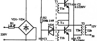
The AC traction substation serves only to reduce the voltage (transformation) of the alternating current received from the power systems. A single-phase current of this voltage powers the contact network. AC traction substations of the 2×25 kV system with a primary voltage of 110 (220) kV have a structural diagram, the peculiarity of which is the use of special single-phase transformers and their connection to the traction network. At AC traction substations, capacitor banks are used. At AC traction substations, in many cases, equipment is installed, the need for which is determined by the type of current and its effect on communication lines and low-voltage electrical networks running parallel to the railway.
Scheme of an AC traction substation.
For this purpose, at traction substations, special installations are used to increase the power factor of the traction load, signaling devices for powering lines with high-frequency current, and compensating devices. At AC traction substations, high-voltage traction voltage cables must be unarmoured and in a non-metallic sheath. In addition, the switchgear must include measures to prevent heating of metal structures by single-phase alternating current.
At 2×25 kV AC traction substations, two working and one backup transformers are installed. Powering traction loads from single-phase transformers assembled according to an open delta circuit forces the installation of additional two or three winding transformers to power regional non-traction consumers.
At combined AC traction substations (for electricity consumers of categories I and II), as a rule, two traction and two separate transformers are installed to power the power load. At AC traction substations built between 1954 and 1961. In auto-blocking power supply circuits at a frequency of 75 Hz, in addition to the listed transformers, autotransformers are installed. In an autotransformer, the low voltage winding is part of the high voltage winding.
The district is powered from alternating current traction substations with a higher voltage of PO kV can be supplied either from three-winding traction transformers or from individual transformers installed at traction substations. If a single supply voltage is required to power the area, the most appropriate power supply circuit is from the third winding of traction transformers. In the presence of an existing district load on two voltages, it may be a more economical option to supply traction and district consumers from separate transformers.
Additional material: How to make a 4G antenna.
The efficiency of a separate power supply scheme increases in cases where it is possible to limit the installation of one transformer to power traction, and also when a traction substation is built near an existing regional substation. The power of transformers STp of AC traction substations depends on the magnitude of the traction load on power arms 1a and /fr and on the power of the railway non-traction S. Due to the high power of AC traction substations, voltages below PO kV are not used to power them. Therefore, when placing such a substation near a district one, it is recommended to place them on the same site.
How does a traction substation work?
Classification depending on purpose
In accordance with the operating conditions, the traction substation can be classified into one of the following groups. For railway transport, support, dead-end, and intermediate varieties are used. In the first case, the installation can be used to power other objects. Dead-end devices are provided with electric current from neighboring substations, and intermediate ones - from two neighboring installations.
Special types are used for trolleybuses and trams. The first group of devices requires the participation of maintenance personnel. The second category is fully automated. The third category includes remote-controlled equipment. The management of such stations does not require the participation of personnel. For the subway, step-down, traction and traction-step-down devices are used. In the first option, the system is powered by city power supply equipment. The second type reduces the voltage to 400-220 V. Its energy is used to power lighting and power devices.
General view of the electrical substation.
Design Guidelines
Transformer power alone is not enough to properly design an installation. A whole list of parameters that affect the operation of the equipment should be taken into account. The amount of voltage and resistance on the buses into which current is supplied. The substation itself has a certain level of resistance, as well as the resistance of the feeder, smoothing unit. When choosing an installation, the total amount of this parameter must be taken into account.
It will be interesting➡ Design and circuit of a three-phase transformer
The design can use a different number of transformers and distributors. When choosing, take into account the operating conditions of the equipment. Using generally accepted formulas, it is necessary to calculate the total value of the required installation voltage. The short circuit power is also taken into account. In most cases, the total power of the equipment, as well as low and high voltage indicators, are taken into account.
Substation for the residential sector.
Structure
The description of the typical circuits of the presented devices is quite complex. However, common features can be identified. The connection in the system is made in accordance with the characteristics of the transport for which the unit is used. The distributor consists of three blocks. The first contains a device that receives high voltage, the second compartment contains a transformer, and the third contains an output for electricity with specified characteristics. There is only one switch. There is a disconnector at the input.
The connection of the primary windings is carried out according to the star circuit. The zero phase must be grounded. The secondary windings are connected in the form of a triangle. One of the phases is grounded and connected to the rail. The metro has a special contactor for this purpose. This rail is intended solely for relieving the stress of an electric locomotive. The other phases feed into two overhead cables. They are sometimes used to supply electricity to other consumers, but mainly traction substations provide power to trolleybuses via overhead wires.
For a tram, this process involves one overhead wire and one ground rail. In most countries of the world, the voltage for such a network is 550 V.
Substation power supply
The traction substation must provide an uninterrupted supply of electricity for vehicle movement. Therefore, many of these units are powered from two autonomous networks at once. In this case, a single-line diagram of a traction substation can be used or using two backup lines to another power source. It is also possible to supply power via jumpers between individual substations.
Substation power supply
If the option of two separate lines is used, each of them must be designed for the maximum load of the unit. Redundant communications must be able to withstand the total load of the connected stations. Previously, a radial circuit was used to power subway networks. It is complex and expensive. It requires too much cable. They didn't seem like it from her. Today, only the above schemes are used. Lines and jumpers allow you to combine equipment into separate groups. If one device inside it fails, other units take over its functions.
Also, when carrying out routine maintenance of units, all operations will be simpler, without causing the system to stop. In this case, it is possible to de-energize only one unit. Other devices will ensure the operation of the line. This approach to routine repairs greatly simplifies the work of personnel, making maintenance less expensive.
Complete equipment
In addition to the basic electrical equipment in the form of converters, rectifiers and other devices serving the contact network, substations are supplemented with protective equipment and fire-fighting equipment. Moreover, these funds are required not only for local maintenance of protective functions, but also to ensure the possibility of providing pre-hospital medical care. The protective equipment of traction substations may include relay devices, circuit breakers, alarm equipment, etc. The structure of modern substations includes sensors that record facts of overloads, overheating and failure of individual segments of telemechanics.
Use of traction substations
The purpose of the traction substation is as follows: to convert and distribute electric current for the purpose of servicing electric vehicles. Substations are divided according to the type of electric current supplied to the contact network - direct and alternating - depending on what type of electric transport is used: electric locomotives of surface railways, subways, trams or trolleybuses. A traction substation can provide electricity to other consumers, not just the railway.
A traction substation can be stationary or mobile. Mobile ones are used quite rarely. The distance between traction substations with direct current in the contact network, they are erected in increments of ten to fifteen kilometers. The distance varies depending on the required power, which depends on the tension in the movement of trains and the terrain.
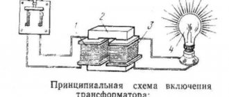
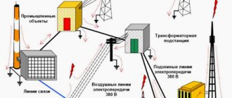
The traction substation is powered from power lines laid over the air on supports, or through a cable network. The external voltage is reduced by the transformer and transferred to the rectifier, from which electric current is supplied to the contact network. Currently, energy recovery is widely used on electric locomotives and other types of electric transport. When braking, electric locomotives, trolleybuses, trams - consumers of electric current, turn into its source. Electric motors become generators and transmit electric current to the contact network, thereby absorbing the kinetic energy of movement and providing braking for electric vehicles.
Substation contact network.
An inverter is used to flow the current back into the power grid. They automatically turn off the rectifiers as soon as the vehicle braking in recuperation mode begins to produce current. On the railway, the nominal voltage level is considered to be 3300 Volts, in subways 825 Volts, in the contact network of trolleybuses and trams 600 Volts.
AC substations differ from similar DC substations in the absence of a rectifier; a step-down transformer supplies current directly to the contact network.
The distance between traction substations that use alternating current is higher than for stations using direct current - up to fifty kilometers. And the voltage that electric vehicles remove is 27.5 kilovolts. Power supply from an external network for them ranges from 110 to 220 kilovolts. The connection diagram of the primary windings of the step-down transformer of such stations is a “star” with a grounded zero phase. The secondary windings are connected in a delta pattern.
One of the phases is grounded and connected to a rail, which serves as one of the contact wires for the electric locomotive. In the subway, this is a separate contact rail, which serves solely to relieve voltage from the subway electric locomotive. The other two phases supply current to two overhead wires on different paths and are also used to supply other electrical consumers.
There are quite a lot of the latter near railways. This includes automation that controls the movement of trains, signaling devices, communications, lighting of platforms and station buildings, their heating and much more. Traditionally, in many areas, the railway power supply system is the only way to supply voltage to populated areas. Therefore, the traction substation is not only used for electric transport, but also supplies populated areas and other consumers with electricity, meeting their needs.
Power lines.
The traction substation and their groups provide service to ground, mainly urban, electric transport - trolleybuses and trams. They convert current from external networks into direct current and transmit it to contact wires or rails. For trolleybuses there are two contact overhead wires, for trams there is one overhead wire and a rail. The voltage used in most countries is 550 Volts.
It will be interesting➡ Necessary conditions for parallel operation of transformers
A traction substation can be remote-controlled, fully automated, or have service personnel. Most often, personnel are present at small stations in small cities. Where the creation of automatic control systems is not economically feasible.
Or, on the contrary, at large traction substations, whose value is too great to have the risk of shutting them down. Often, personnel are present only at one of the traction substations, from where other stations included in the overall system are remotely controlled. The presence of personnel does not exclude automatic control. In this case, the person is assigned the role of an observer-controller who can intervene in the operation of the substation in emergency cases requiring decision-making and in emergency situations.
How does a traction substation work?
Fully automated stations are used where the intensity of train traffic is low, and the stop should not entail far-reaching consequences in terms of safety. The most reliable and economical control system is remote. A traction substation can be single-unit or multi-unit. Single-unit ones are used where a centralized supply of electricity is not required, on branches. They are quite rare because they do not provide a reliable supply of electricity. If the unit fails, the entire network served by the substation is de-energized. Therefore, two-unit substations are most often used. There are both three-unit and four-unit ones.
The presence of several units significantly increases operational reliability. When one unit fails, the second one turns on, which ensures uninterrupted operation. Also, the presence of more than one unit gives flexibility to the work at times of maximum load. Combining several substations into a single group controlled from one center makes it possible to make them interchangeable, reduces the cost of construction and operating costs.
Interesting read: How to solder aluminum with your own hands.
Since the main condition for the operation of a traction substation is uninterrupted operation, they are all powered simultaneously from two different external networks. Power supply can be carried out via separate lines, or from one using the main and backup lines to another substation; the option of connecting with jumper cables between substations is possible.
When using two separate lines, both must be designed for the maximum load of the substation. The backup connection must simultaneously withstand the load of the connected stations; the connection with a jumper cable must withstand one. Scheme number two is most often used in the metro, as it is quite reliable, economical and easy to manage.
Previously, when the construction of the metro in the country was just beginning, a radial line design was used to power substations from city networks. However, such a scheme is quite complex; it involves many cables and cells. Therefore, it was soon abandoned. Now powering is done using lines and jumpers. This ensures the consolidation of substations into separate groups. If one of the step-down transformers in the group fails, the others redistribute its load.
Recommendations for selection
The main criterion for the effectiveness of using a particular type of installation is the compliance of the parameters with the operating conditions, in particular, the level of the supplied load. If a traction or pole transformer substation is selected, its typical design implies the need to perform the following actions:
- Selection of connection diagram and connection of main components;
- Determination of the most suitable option for current-carrying devices and components;
- Based on the calculated values of electrical parameters, the main components of such equipment (switchgears, transformers, switches, disconnectors, protection elements, charging batteries) are selected.
Similar actions are performed in the case when a mast transformer substation is selected; a typical project will also largely consist of a calculation part.
What is a traction substation and how is it designed?
Installation nuances and regulatory documentation
The main feature of the principle of installation of equipment used to power railway electric transport is that all work is carried out with the direct participation of electrical installation trains. The list of key tasks includes the installation of the traction substation itself, and at the same time the sectioning posts, telemechanical equipment and contact network. Equipment such as pole-mounted transformer substations are connected in a slightly different way, given that all the main components are mounted on a support.
STN TsE 12-00 “Standards for the production and acceptance of construction and installation work during the electrification of railways” define a number of requirements for the installation of such equipment. For comparison, a mast-mounted transformer substation involves preparing a pit for installing a support, checking the accuracy of the installation using plumb lines, installing the main components on the supporting structure, and connecting all elements.
Thus, traction units are distinguished by a variety of designs, which, on the one hand, somewhat complicates the choice of such equipment, and on the other, allows you to choose the most suitable option. But pole-mounted transformer substations are equipment for a narrower purpose and represent a dead-end design option for a certain range of power values and voltages. When choosing any of these types of equipment, the level of load withstand, the connection diagram, as well as the compliance of the main parameters with the operating conditions are taken into account.
Installation of a traction substation.
Carrying out repair work
At the time of the overhaul, the responsible person receives a document indicating the results of previous tests. Based on his analysis, the engineer issues a conclusion indicating problem areas where repair operations will be carried out. At a basic level, bolted, contact and welded connections are updated. When performing routine repairs, fastening units are restored, cracks in insulation are eliminated, seals and seams are reinforced. In extreme cases, a traction substation may undergo reconstruction with the replacement of main equipment. Typically, such measures are carried out after changing network parameters, when voltage values increase or decrease. Modernization is also common as part of expanding the range of station tasks.