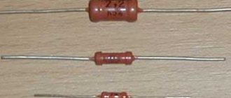
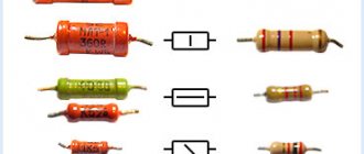
People who repair household appliances remember inconvenient Soviet resistors, the capacity of which was often very difficult to determine without desoldering it from the board. This situation arose because the capacity was printed in the form of numbers on only one side of the device and it was not always possible to see them. Subsequently, color marking of resistors came into use - colored circular stripes were applied to the body, which are visible in any position of the element. Let's look at how to correctly determine the value of permanent resistors using strips.
Introduction
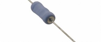
A resistor is an electronic device that has a certain resistance. Its main task is to convert current into voltage and vice versa. Due to its small size, it is not always possible to apply and read markings from a resistor - for example , a 0.25-watt device, quite often used in systems engineering, has a length of no more than 3.2 mm with a diameter of 1.8 mm . That is why the color marking scheme was developed. It is international, it was approved by IEC (International Electrotechnical Commission) and the requirements of GOST 175-72.
Marking resistors with stripes
Stripes should be read from left to right. The first ring is applied closer to the wire exit from the device.
Ready-made solutions for all areas
Mobility, accuracy and speed of counting goods on the sales floor and in the warehouse will allow you not to lose days of sales during inventory and when receiving goods.
Speed up your warehouse employees' work with mobile automation. Eliminate errors in receiving, shipping, inventory and movement of goods forever.
Speed, accuracy of acceptance and shipment of goods in the warehouse is the cornerstone in the E-commerce business. Start using modern, more efficient mobile tools.
Increase the accuracy of accounting for the organization’s property, the level of control over the safety and movement of each item. Mobile accounting will reduce the likelihood of theft and natural losses.
Increase the efficiency of your manufacturing enterprise by introducing mobile automation for inventory accounting.
The first ready-made solution in Russia for tracking goods using RFID tags at each stage of the supply chain.
Eliminate errors in comparing and reading excise duty stamps for alcoholic beverages using mobile accounting tools.
Obtaining certified Cleverence partner status will allow your company to reach a new level of problem solving at your clients’ enterprises.
Use modern mobile tools to carry out product inventory. Increase the speed and accuracy of your business process.
Use modern mobile tools to account for goods and fixed assets in your enterprise. Completely abandon accounting “on paper”.
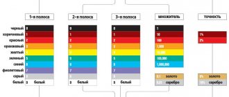
Color Chart
To read resistor color stripes, you can use this table:
| Color | Digital value |
| Black | 0 |
| Brown | 1 |
| Red | 2 |
| Orange | 3 |
| Yellow | 4 |
| Green | 5 |
| Blue | 6 |
| Violet | 7 |
| Grey | 8 |
| White | 9 |
| Gold | -1 |
| Silver | -2 |
The last numbers are used for the decimal multiplier. It should also be remembered that there are six accuracy levels provided by GOST. For the E6 series, a deviation of 20% is allowed, for E12 - 10%, E24 - 5%, E48 - 2%, E96 - 1%, E 192 - 0.5%.
Reading stripes is easier than markings
Alphanumeric designations
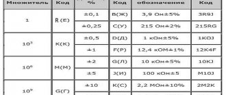
They are conceived quite logically: denominations are written in numbers, and multipliers are written in letters. The latter will have to be remembered, which is not very convenient. Another nuance is that the code can come from all representatives of the alphabet, for example, “33” - this indicates a standard tolerance of 20%.
This is true for MLT, that is, metal-film varnished heat-resistant electronic elements - the most popular in the times of the late USSR and still working in well-preserved retro equipment.
Transcription examples
The principle is clear, plus, to make the process easier, you can substitute the Cyrillic alphabet instead of English letters. Then all that remains is to remember that “E” and “R” are equal to one, and the others are quite consistent with SI.
Labeling rules
Classic color marking of resistors consists of 3-6 stripes/rings. The more stripes, the greater the measurement accuracy. Let's look at the most popular options.
Devices with three stripes
Such marking is used only for those elements that have “planned” deviations of no more than 20%. The numbers related to colors can be taken from the table above. The first and second circles show the resistance of the device, the third - the multiplier indicator.
If we designate the first strip D1, the second D2, the third E, then the formula for calculating the resistance will look like this:
R=(10D1+D2)*10E
For example, on the resistor you are looking for, the first stripe is red, the second is green, and the third is yellow. We are looking for resistance (10*2+5)*104=25*10 to the 4th power=250000 Ohm or 250 kOhm.
Devices with 4 stripes
Used for devices with an accuracy of up to 5-10% (series E12 and E24 according to GOST marking). The color marking scheme for resistances remains the same: the first two rings are the resistance rating, the third is the decimal multiplier, the fourth is the tolerance. Gold tolerance - 5% (applies to the E24 series), silver - 10% (E 12 series). In this case, the formula looks like this: R=(10D1+D2)*10E±S, where the first stripe is D1, the second is D2, the third is E, the fourth is S.
Example:
if you see a device with 4 stripes of green, orange, red and gold, then the resistance will be R=(50+3)*10 second power=5300 Ohm+-5% or 5.3 kOhm ± 5%.
4 strip resistors
Devices with 5 stripes
Similar marking of resistors by strips is used for strips E48 - 2%, E96 - 1%, E 192 - 0.5%. The technique for counting the first three bands remains the same, the fourth indicates the decimal multiplier, the fifth indicates the tolerance level. The formula is as follows: R=(100D1+10D2+D3)*10E±S, where D1, D2 and D3 are the first three circles, E is the fourth, S is the fifth. Tolerances are indicated as follows:
- E48 (2%) - red;
- E96 (1%) - brown;
- E192 (0.5%) - green;
- 0.25% - blue;
- 0.1% - purple;
- 0.05% - gray.
Six-band devices
Professional repairmen know that some resistors have a so-called temperature resistance coefficient, or TCR for short. This parameter shows by what amount the resistance of the element increases/decreases when the temperature changes by 1 degree. This coefficient is measured in ppm/OC (parts per million or millionth of the available nominal value, divided by the number of degrees). Let's look at the designation of resistors by color on the sixth ring:
- Brown color - 100 ppm/OC.
- Red - 50 ppm/OC.
- Yellow - 25 ppm/OC.
- Orange - 15 ppm/OC.
- Blue - 10 ppm/OC.
- Violet - 5 ppm/OC.
- White - 1 ppm/OC.
Let's look at an example of identifying a resistor by color marking .
for 6 rings. For example, we have a resistor with red, green, purple, yellow, brown and orange stripes. The resistance will be equal to (100*2+10*5+7)*104 +-1% (15ppm/OC) or 2570000±1% (15ppm/OC) or 2.57 ±1% (15ppm/OC) MOhm.
Attention:
the sixth ring is often used to calculate the element's reliability factor. If it is of standard width, it determines the ppm/OC coefficient; if it is one and a half times wider, it shows the percentage of element failures per thousand hours of operation.
The color designations in this case are as follows:
- Brown color - up to 1 percent failure rate.
- Red color - no more than 0.1% failures.
- Orange color - no more than 0.01% failure rate.
- Yellow - no more than 0.001% failures per 1000 hours of operation.
The following option can be used as a worksheet to determine resistance:
Resistor Value Reading Table
Why are identification marks needed?
Studying a typical low power component (0.05 or 0.125 W) will help clarify the reasons for the color coding of resistors. With a length of 3-5 mm, the diameter of the element is 0.8-1.2 mm.
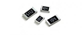
Marking of SMD resistors
To present information in abbreviated form, you can use “classic” encoding. The nominal value of 2,200 kOhm is converted to “2K2”. Here “K” not only denotes the multiplier prefix “kilo-”, but also serves as a separating comma - 2.2 kOhm.
It is difficult to apply clear numbers and letters on a curved surface with a limited area. The slightest defect complicates correct and quick identification. It is enough to make a small scratch during dismantling to create additional difficulties.
Color coding has the following advantages:
- simplicity and manufacturability of the application process;
- the ability to provide the necessary information in full;
- ease of reading data with precise identification of individual design elements;
- high resistance to adverse external influences.
To properly study this topic, it is necessary to clarify the definitions of the main technical parameters of passive elements. Nominal electrical resistance is indicated in ohms and derivative multiples using the appropriate prefix. Kilo-ohms is a multiplier of 10 to the third power or 1,000.
The minimal influence of reactive resistance components (inductive and capacitive) is neglected when creating standard electrical devices. Therefore, such indicators are not displayed in coded digital markings. Manufacturers indicate this and other additional data in the accompanying documentation for precision products. They are necessary for accurate calculations of equipment that processes RF and microwave signals.
Power dissipation is an important parameter. It must be taken into account to select a product that corresponds to a certain maximum current in the circuit. If calculated incorrectly, excessive heat will destroy the resistor.
It should be emphasized! The actual value of electrical resistance depends on the temperature of the conductor. However, power is not indicated by color indication.
The possible deviation of the nominal value (tolerance) is selected taking into account the initial requirements for the radio engineering design. The value of this parameter is determined by the color or number of stripes. The corresponding decryption techniques are presented below.
Additional markers indicate:
- MTBF;
- level of dependence of resistance on temperature changes;
- production technology.
Wirewound resistors
For wirewound resistors, a slightly different color classification of resistors is adopted. In any case, the first stripe will be a wide white stripe, which indicates the manufacturing technology (wire). They cannot have more than 4 stripes; the last ring indicates the properties of the microelement. Study our table - it will allow you to understand how to correctly read the ratings of wire devices.
Circuit for wirewound resistors
Online calculator
Interface of the program “Resistor 2.2”
Modern technologies today greatly facilitate the work of both professionals and radio amateurs. In addition to accessible measuring equipment, today in Internet resources dedicated to radio engineering there are a huge number of online calculators for determining the resistance of resistors by marking.
Simple, and generally reliable programs allow you to accurately determine the rating of almost any radio component; more advanced and powerful engineering programs used in packages for design engineers allow you not only to find out the resistance value, but also to find an appropriate replacement and determine the option the performance of the circuit itself.
One of such programs is the Resistor 2.2 program; it is simple, convenient and does not require deep knowledge of computer technology. A simple interface and convenient working elements allow you to work both online and without it.
How to use?
Like most applied engineering programs, the Resistor 2.2 program is an online calculator that allows you to determine the resistance value using various most common types of encoding:
- Standard 4 or 5 color markings.
- Philips branding of various types of resistances.
- Non-standard color coding from Panasonic, Corning Glass Work.
- Regular code marking.
- Regular encoding Panasonic, Philips, Bourns.
After unpacking the archive, the program, which does not require registration, is immediately ready to work. In the window, from the proposed options, the desired parameter is selected and further identification is made using the existing code on the element body.
For ease of identification, an image of the defined encoding is clearly shown in the upper window. Color rings are applied to the body of the radio component in accordance with the values specified by the user, thus making it possible to visually compare the encoding with the real element.
The numerical value of the element's denomination is immediately displayed at the bottom.
How to determine the resistor value by color coding using an online program?
Low-power parts have very small dimensions (length - a few millimeters, diameter - about a millimeter), so it is difficult to apply alphanumeric markings. For such products, colored dots and lines are used that characterize the main parameters. Advantages of a color scheme:
- easy to read;
- easy to apply;
- allows you to convey the necessary information.
The number of color stripes depends on the accuracy that the part provides:
- 3 stripes – 20% accuracy;
- 4 strips – 5 and 10%;
- 5 and 6 stripes are the most accurate models.
Differential machine or RCD?
A differential circuit breaker can be distinguished from an RCD in the following ways:
- According to the inscription on the case. On modern devices, manufacturers usually indicate the name of the device;
- By marking: RCBO - automatic differential current switch (differential circuit breaker) VD - differential switch. (RCD)
RCD Diff. machine
- According to the time characteristic of the response time: If the letters A, B, C are indicated in front of the current rating (for example, C 16A) - we have a differential. machine. These letters indicate the speed of the machine, A - the fastest, C - the slowest, but also the cheapest. Typically, machines with a C-characteristic are used for domestic needs.
- According to the diagram shown on the device body.
The RCD has only a differential transformer: In the differential circuit diagram, in addition to the differential. transformer, the windings of the thermal and electromagnetic release are indicated: