DC power supplies, the circuit of which includes a rectifier (AC/DC converter), are popular devices widely used in automated test systems designed to test electrical equipment, modules, and wiring diagrams. They are also used to power various electronic equipment, electric motors, charge batteries, and carry out electrochemical processes. They convert AC mains voltage into stabilized DC voltage. Many models provide the ability to adjust output parameters.
A separate type of power supply (PS) is made up of converters (DC/DC converters). They operate on DC power. Their scope of application includes automated process control systems, energy, transport, telecommunications and information technologies, security and fire systems.
The main technical characteristics of DC power supplies are:
- Nominal input voltage.
- Rated output voltage and its adjustment range.
- Maximum load current.
- Accuracy of output voltage stabilization.
- Efficiency
In addition to the basic characteristics, other operating parameters are also of great importance, which we will consider in more detail.
Noises and pulsations
This characteristic of DC power supplies determines the quality of the output signal, as well as the choice between switching and linear power supplies. Switching converters are essentially noise generators. Devices that use pulse-width modulation to control the switching of power switches create noise in a certain frequency band. The noise repetition rate depends on the switching frequency of the switching power supply, and the amplitude is highly dependent on the equipment topology. Ripple is a fluctuation in the output voltage that is associated with the charging and discharging of the device. It can be reduced by increasing the input or output capacitance.
For many tasks related to testing electrical equipment, it is advisable to use linear rather than pulsed power supplies. Despite the fact that they are characterized by low efficiency, size and weight, and the generation of a significant amount of heat, they can be used in applications where high power is not required (up to 200 W per channel). Linear devices generate high-frequency noise that can be easily filtered out. They also have a high response rate to load changes. If the task at hand does not impose increased requirements on the level of noise and pulsation, it is better to choose a pulse converter. It is characterized by high power, compactness, wide adjustment ranges, and flexibility of settings.
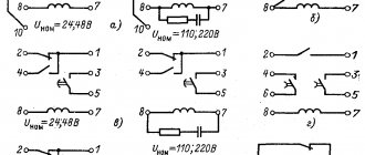
Conventional graphic symbols of ERE in electrical, radio engineering and automation diagrams
1— transistor of the pnp structure in the housing, general designation;
2— transistor of the p-p-p structure in the housing, general designation,
3 - field effect transistor with pn junction and n channel,
4 - field effect transistor with pn junction and p channel,
5 - unijunction transistor with n-type base, b1, b2 - base terminals, e - emitter terminal,
7 - rectifier diode,
8 - zener diode (avalanche rectifier diode) one-sided,
9 - thermal-electric diode,
10 — diode thyristor, erasable in the opposite direction;
11 - zener diode (diodolavin rectifier) with bidirectional conductivity,
12 - triode thyristor.
14 - variable resistor, rheostat, general designation,
Read also: How to increase the fire in a lighter
15 - variable resistor,
16 - variable resistor with taps,
17 — construction resistor-potentiometer;
18 - thermistor with positive temperature coefficient of direct heating (heating),
20 - constant capacitor, general designation,
21 - polarized constant capacitor;
22 — oxide polarized electrolytic capacitor, general designation;
23 - constant resistor, general designation;
24 - constant resistor with a rated power of 0.05 W;
25 - constant resistor with a rated power of 0.125 W,
26 - constant resistor with a rated power of 0.25 W,
27 - constant resistor with a rated power of 0.5 W,
28 - constant resistor with a rated power of 1 W,
29 - constant resistor with a rated dissipation power of 2 W,
30 - constant resistor with a rated dissipation power of 5 W;
31 - constant resistor with one symmetrical additional tap;
32 - constant resistor with one asymmetrical additional tap;
Output voltage change rate
This is an important parameter that is of great importance in the field of testing electrical appliances. During testing, different voltages are applied to the equipment to verify that it is functioning correctly within its operating range. The faster the power supply responds to changes in settings, the higher the testing performance. In standard devices, the time to set the output voltage with an accuracy of 1% is on average 50-500 ms. There are special circuits for regulated DC power supplies that can reduce this figure to 1-4 ms.
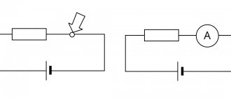
Conventional graphic symbols of ERE in electrical, radio engineering and automation diagrams
65 - socket for detachable contact connection,
66 - contact for removable connection, for example using a clamp
67 - contact of a permanent connection, for example, made by soldering
68 — single-pole push-button switch with self-resetting closing contact
69—breaking contact of the switching device, general designation
70 — contact of the switching device (switch, relay) making, general designation. Single pole switch.
71 - switching device contact, general designation. Single pole double throw switch.
72—three-position switching contact with neutral position
73 - closing contact without self-return
74 — push-button switch with normally open contact
75 — push-button pull-out switch with normally open contact
76 — push-button switch with button return,
77 — push-button pull-out switch with normally open contact
78 - push-button switch with return by pressing the button a second time,
79 - electrical relay with normally open and switching contacts,
80 - relay polarized for one direction of current in the winding with a neutral position
81 - relay polarized for both directions of current in a winding with a neutral position
82 - electrothermal relay without self-reset, with return by pressing the button a second time,
83-plug single-pole connection
84 - socket of five-wire contact plug connection,
85 pin removable coaxial connection
86 - contact connection socket
87 - four-wire connection pin,
88 four-wire connection socket
89 - jumper switching breaking circuit
Any electrical circuits can be presented in the form of drawings (circuit and wiring diagrams), the design of which must comply with ESKD standards. These standards apply to both electrical wiring or power circuits and electronic devices. Accordingly, in order to “read” such documents, it is necessary to understand the symbols in electrical circuits.
Response time to load changes
This parameter determines how quickly the power supply reacts to load changes or power surges. If the output current changes rapidly over a wide range of values, the output voltage also begins to decrease or increase at a high rate. The time it takes for a device to stabilize its characteristics is called reaction time to a change in load. Due to the use of feedback in the topology to control the output voltage, switching power supplies are characterized by a relatively slow response.
To protect the devices under test from severe overloads, it is recommended to use a preload. It is connected in parallel with the device under test and limits voltage surges. Modern switching power supplies have a response time of 40-80 µs, and linear ones - up to 1 µs.
Current sources on field-effect and bipolar transistors.
Circuits of current generators, types of current mirrors, Online calculator for calculating elements of current sources.At today’s event dedicated to the opening of the “Cultural and Leisure Center of the Lokhov Municipality”, we will talk about the types of sources of constant and, preferably, stable output current. - If voltage can be understood with the mind, then current can only be understood with feeling! — the head of the artistic needlework circle, Semyon Samsonovich Eldykin, began his report. - The purpose of our amateur radio session today is to master the ordered movement of free electrically charged particles - as a sum of knowledge, physical skills and innate skills. “How to ground an ungrounded ground? How much vodka do you need to drink in grams to reduce body resistance by 1 kOhm? And how not to enter into intimate relationships with electricity? - will be the topic of our scientific colloquium.
Thanks to Semyon Samsonovich for the introductory words, but it’s time for us to move closer to the topic indicated in the title. Let us indulge in encyclopedic profundity:
“ A current source is an element, a two-terminal network, the current strength through which does not depend on the voltage at its terminals (poles). The terms current generator and ideal current source are also used…” Wikipedia teaches us.
Let's add to the editorial staff. The current source must have a large internal differential resistance , such that when the load resistance changes, the current strength in the load practically does not change. This opportunity is provided to us by a bipolar transistor on the collector side, a field switch on the drain side, or an operational amplifier between the inverting input and output.
There are several basic characteristics that characterize a current source . The first and main one is the output current. Secondly, its output impedance, which determines how much the source current varies depending on the load impedance. The third specification is the minimum and maximum voltage at the source output at which the node operates properly, i.e. the output transistor is in active mode. Fourth, temperature stability and the ability to withstand power supply voltage fluctuations.
To warm up, let's look at the circuits of the simplest current generators (sources) using transistors and operational amplifiers.
Fig.1
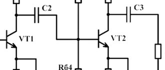
The bipolar transistor current source circuit is the worst. It has a full bouquet of shortcomings - temperature instability, the dependence of the current on fluctuations in the voltage of the power source, and the presence of the notorious Earley effect (the effect of the influence of the voltage between the collector and the base on the collector current). Here, the input divider on resistors R1, R2 sets the base current of the transistor Ib, the output current, to a first approximation, can be considered equal to In = Ik≈β×Ib.
The field-effect transistor circuit is not so sensitive to the instability of the power source, but it has another significant drawback - the practical impossibility of calculating the generator output current in advance due to the significant scatter in the parameters of these types of semiconductors. The maximum current of this type of source is equal to the initial drain current at R1=0 (datasheet characteristic), the minimum is limited by the voltage drop across the current-setting resistor R1.
Current generators based on operational amplifiers (inverting on the left, non-inverting on the right) are quite efficient devices that are close analogues of ideal current sources, and are practically free of the disadvantages inherent in transistor circuits. The only significant “but” in some cases is that the load is “floating”, i.e. not connected on any side to the ground. The current through the load is described with almost 100% accuracy by the formula In = Uin/R1.
Have you warmed up? The time has come to get rid of the shortcomings of the simplest current sources that we coughed up above.
Fig.2
The current stabilizer circuits presented in Fig. 2 will be useful in devices working with end consumers that are sensitive not so much to voltage stability as to the constancy of the current flowing through them. You don’t have to look far for examples - power supplies for LEDs, gas-discharge lamps, battery chargers, etc. All of them require a constant current or a current varying according to a certain algorithm at the output. The operating principle of the above schemes is extremely simple. As the load current increases, the voltage drop across the current-setting resistor R1 also increases proportionally. When this voltage drop reaches a level of ≈0.6V, transistor T1 begins to open, reducing the value of Ube (or Uzi) of the second transistor T2. It begins to close, and accordingly, the amount of current flowing through the load decreases. For a circuit based on a bipolar transistor, the value of the resistor Rb should be chosen based on considerations Rb For a field operator, due to its high input resistance, the value of the resistor Rз1 can be chosen quite high (tens of kilo-ohms). The only thing you need to keep a close eye on is the maximum permissible value of the gate-source voltage of the transistor. If it is less than Ep, you should add an additional resistor Rз2 of such a value that the formed divider brings the voltage at the gate within acceptable limits. The output current is calculated using the simple formula Iн≈0.6/R1. There is no temperature compensation in these circuits; the change in output current is ≈ 0.3% per °C.
| To reduce the dependence of the output current on supply voltage fluctuations, current sources (Fig. 4), called double current mirrors, have been widely used. The mechanism works as follows: Suppose the supply voltage has increased. Then the voltage drop across resistor R1 also increases. This leads to a decrease in the base potential of transistor VT3, transistor VT3 will close, its current Ie3 will decrease, and the base current Ib2 and In will also decrease and return to its original state. Ik1≈(Ep-1.4)/(R1+ Re1), In≈ Re1×(Ep-0.7)/(R1× Re2+ Re1× Re2). | |
| Fig.5 | The current source shown in Fig. 5, is called the Wilson current mirror circuit and provides a high degree of output current constancy by suppressing the manifestations of the Early effect (the effect of the voltage between the collector and the base on the collector current). Transistors T1 and T2 in this circuit are connected in the same way as in a conventional current mirror, but thanks to transistor T3, the collector potential of the current-setting T2 is fixed and does not affect the output current. All formulas are similar to the previous description: Ik1≈(Ep-1.4)/(R1+ Re1), In≈ Re1×(Ep-0.7)/(R1× Re2+ Re1× Re2). |
| Fig.6 | The cascode current generator shown in Fig. 6 has the advantages of a very high internal resistance and a significant reduction in the Early effect. The dynamic internal resistance of such a current reflector exceeds several MOhms. And again - everything is the same: Ik1≈(Ep-1.4)/(R1+ Re1), In≈ Re1×(Ep-0.7)/(R1× Re2+ Re1× Re2). It is easy to notice that for all types of reduced current mirrors, the formula for calculating the output current is the same. The formula is approximate and does not take into account the influence on the calculated indicators of insignificant values of the base currents of transistors, but makes it possible to calculate the values of current-setting elements with an error not exceeding 5-7%. |
If it is necessary to generate reverse current, you should turn the circuit upside down and replace the NPN transistors with reverse conduction semiconductors.
And according to tradition, I will provide a table that allows you to not bother too much, if you want to translate the described nodes into real life.
CALCULATION OF CURRENT SETTING ELEMENTS OF CURRENT SOURCES ON BIPOLAR TRANSISTORS.
Current sources based on field-effect transistors, due to the significant spread of parameters of this type of semiconductor, have found practical application mainly in the production of analog integrated circuits. At the same time, when using MOS structures of field-effect transistors, the circuitry of current mirrors is practically no different from the above current sources on bipolar counterparts.
Fig.6
Designing current sources using discrete field-effect transistors is, in my opinion, a rather impractical task. Another thing is specially designed semiconductors called current-stabilizing diodes (CRDs), which are based on an n-channel field-effect transistor. Fig.7
Field diodes have only two terminals and are optimized in terms of current-voltage characteristics. In their manufacture, it is possible to achieve a zero temperature coefficient by combining the CRD with a resistor that has the same but opposite temperature coefficient. Current-stabilizing diodes are not very well known among the broad masses of the amateur radio community, but in the meantime they are actively produced by bourgeois industrialists, they have a decent range of currents and a fairly wide range of operating voltages.
And on the next page we will continue the topic - we will devote it to current sources on operational amplifiers, as well as voltage-to-current converters on op-amps and transistors .
Possibility of parallel and serial connection of IP
Parallel connection of power supplies increases the output current. Many power supplies are equipped with a specialized parallel control bus. It allows you to create a single configuration from multiple sources. The system automatically determines which devices are master and which are slave.
Series connection of power supplies is used if increased voltage is required. However, it should not exceed the electrical insulation strength of the output terminals.
Types of electrical circuits
In accordance with ESKD standards, diagrams mean graphic documents on which, using accepted notations, the main elements or components of a structure, as well as the connections connecting them, are displayed. According to the accepted classification, there are ten types of circuits, of which three are most often used in electrical engineering:
- Functional, it shows the node elements (depicted as rectangles), as well as the communication lines connecting them. A characteristic feature of this scheme is minimal detail. To describe the main functions of nodes, the rectangles displaying them are signed with standard letter designations. These can be various parts of the product that differ in functionality, for example, an automatic dimmer with a photo relay as a sensor or a regular TV. An example of such a scheme is presented below.
Example of a functional diagram of a television receiver - Fundamental. This type of graphic document displays in detail both the elements used in the design and their connections and contacts. The electrical parameters of some elements can be displayed directly in the document, or presented separately in the form of a table.
Example of a circuit diagram of a milling machine
If the diagram shows only the power part of the installation, then it is called single-line; if all elements are shown, then it is called complete.
Single Line Diagram Example
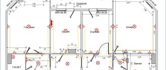
- Electrical wiring diagrams. These documents use positional designations of elements, that is, their location on the board, method and order of installation are indicated.
Installation diagram of a stationary flammable gas detector
If the drawing shows the wiring of the apartment, then the locations of lighting fixtures, sockets and other equipment are indicated on the plan. Sometimes you can hear such a document called a power supply diagram; this is incorrect, since the latter shows how consumers are connected to a substation or other power source.
Having dealt with the electrical circuits, we can move on to the designations of the elements indicated on them.
Digital programming
Many power supplies support digital programmability for constant voltage (CV) or constant current (CC) modes. The devices operate in voltage stabilization mode provided that the load current is less than the set value. After the electric current reaches a threshold value, the IP switches to current stabilization mode. The output voltage can be limited to prevent power overload. Configuration is carried out through the device control panel or from a computer via USB, LAN, GPIB interfaces.
Programming provides advanced control capabilities. For example, you can sequence changes in voltage and current, generate sawtooth and other signals for testing fuses and various electrical appliances.
Regulations
Taking into account the large number of electrical elements, a number of normative documents have been developed for their alphanumeric (hereinafter referred to as BO) and conventional graphic designations (UGO) to eliminate discrepancies. Below is a table showing the main standards.
Read also: Connecting copper and aluminum wires on the street
Table 1. Standards for graphic designation of individual elements in installation and circuit diagrams.
| GOST number | Short description |
| 2.710 81 | This document contains GOST requirements for BO of various types of electrical elements, including electrical appliances. |
| 2.747 68 | Requirements for the dimensions of displaying elements in graphical form. |
| 21.614 88 | Accepted codes for electrical and wiring plans. |
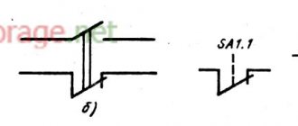
| 2.755 87 | Display of switching devices and contact connections on diagrams |
| 2.756 76 | Standards for sensing parts of electromechanical equipment. |
| 2.709 89 | This standard regulates the standards in accordance with which contact connections and wires are indicated on diagrams. |
| 21.404 85 | Schematic symbols for equipment used in automation systems |
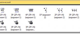
It should be taken into account that the element base changes over time, and accordingly changes are made to regulatory documents, although this process is more inert. Let's give a simple example: RCDs and automatic circuit breakers have been widely used in Russia for more than a decade, but there is still no single standard according to GOST 2.755-87 for these devices, unlike circuit breakers. It is quite possible that this issue will be resolved in the near future. To keep abreast of such innovations, professionals monitor changes in regulatory documents; amateurs do not have to do this; it is enough to know the decoding of the main symbols.
Power supplies with linear stabilizers
A linear regulator power supply is simply an unregulated power supply followed by a transistor circuit operating in its "active" or "linear" mode, hence the name linear regulator. A typical linear regulator is designed to output a fixed voltage for a wide range of input voltages, and simply drops any excess voltage across it to provide maximum output voltage to the load. This excess voltage drop results in significant power dissipation in the form of heat. If the input voltage becomes too low, the circuit will become unregulated, meaning it will not be able to maintain a constant voltage. It can only discard excess voltage, but cannot compensate for the lack of voltage in the unstabilized source section. Therefore, it is necessary to maintain the input voltage above the required output voltage by at least 1-3 volts, depending on the type of stabilizer. This means that power equivalent to at least 1-3 volts times the full load current will be dissipated by the regulator circuit, generating a lot of heat. This makes power supplies with linear regulators quite inefficient. Plus, to get rid of all that heat, they have to use large radiators, which makes them big, heavy, and expensive.
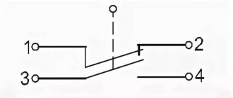
How are single line diagrams depicted?
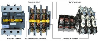
Single-line diagrams will be needed to assemble electrical panels. They are based on a residual current device (abbreviated RCD), contactors, automation, neutral and ground buses, and other equipment. When working with such a scheme, you need to be especially careful, since some of the symbols are of a similar nature. An example is relay coils, for which only a rectangle is used for graphics. The contactor and switch are designated in the same way; the main thing here is to notice one small element on the stationary contact.
When drawing up a single line diagram, it is important to understand that some symbols are indicated by several icons: for example, the presence of two check marks in a row indicates the number of wires.
Unstabilized power supplies
An unregulated power supply is the simplest type, consisting of a transformer, rectifier and low-pass filter. These power supplies typically have large voltage ripple (i.e., rapidly changing instability) and other AC voltage "noise" superimposed on the DC supply voltage output. If the input voltage changes, the output voltage will change proportionally. The advantage of an unregulated power supply is that it is cheap, simple and efficient.