Figure 2a - Cold junction compensation
Accurate performance of CHS is critical to the accuracy of temperature measurements. The accuracy of the CHS depends on two factors: the accuracy of the reference temperature measurement and the proximity of the reference measurement point to the cold junction. Many transmitters use an isothermal terminal block (often made of copper) with a built-in precision thermistor, RTD, or transistor to measure the temperature of the block.
TIP: Use field transmitters rather than hard-wired transmitters directly to the control room.
Thermal resistances
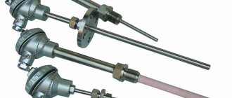
Thermal resistance is another type of sensor based on the effect of temperature on an electrical conductor. When current passes through a conductor, it heats up, part of this heat goes into the environment, and the rest is spent on heating the wire itself. When equilibrium is established, the temperature of the wire depends both on the current flowing through it and on the environment. A change in the temperature of the conductor affects its resistance; it is this dependence that makes it possible to measure the ambient temperature by measuring the resistance of the conductor. The operation of a sensor called thermal resistance is based on this principle.
Platinum thermal resistance (Pt 100) is one of the most accurate, as it has a clear linear dependence in the range from – 220°C to +850°C. Where less accuracy is needed, nickel sensors are used, since the dependence of resistance on temperature is less linear and the properties change over time. They have a narrower measurement range - from -60°C to +180°C.
Features of various types of thermocouples.
Type S (rhodium-platinum thermocouple), Type R (rhodium-platinum thermocouple)
The range of recommended operating temperatures is from 400 °C to 1350 °C. At temperatures above 900 degrees there is an increased risk of contamination; use in an oxidizing atmosphere is acceptable.
Type B (platinum-rhodium-platinum-rhodium thermocouple)
More resistant to contamination than types S or R, can also be used in oxidizing environments, operates in a higher temperature range - from 600 °C to 1500 °C.
Type J (Iron Constantan Thermocouple)
This type is best suited for use in rarefied atmospheres. Due to the tendency of iron to oxidize, temperatures below 0 °C should be avoided. Indications change due to aging. Maximum operating temperature 500 °C.
Type T (copper-constantan thermocouple)
The advantage of this type of sensor is its resistance to high humidity, insensitive to the amount of oxygen in the atmosphere, and can be used at subzero temperatures.
Type E (chromel-constantan thermocouple)
A highly sensitive sensor with fairly homogeneous electrodes, designed primarily for low temperatures.
Type K (thermocouple chromel alumel)
It has a wide range - 100 °C to +1000 °C, however, it must be taken into account that in the range from 200 to 500 °C inaccurate readings are possible due to the hysteresis effect. Sensitive to oxygen content - the optimal atmosphere is neutral or oxygenated. Not suitable for use in sulfur containing atmospheres.
Type N (nicrosil-nisil thermocouple)
More stable in the range from 200 to 500 °C than type K, sensitive to impurities, operating temperature up to 1200 °C, the most accurate base metal thermocouple.
Tips for using thermocouples:
- protect the thermocouple from mechanical stress and vibration
- avoid sharp temperature gradients along the length of the thermocouple
- use the sensor only within operating temperatures, preferably with a margin
- carry out verification and diagnostics
- • use protection when working in an aggressive environment
To order a thermocouple you must specify:
- sensor type;
- sensor geometry (sketch);
- lead length;
- presence of a connector;
- quantity.
Based on your sketch, we will select a sensor from standard models or offer you a custom-made one according to your dimensions. To obtain a catalog of temperature sensors, please contact our managers.
Thermocouple Conductor Color Standards
Thermocouple conductors consist of two separate thermoelectrodes (positive and negative) with colored insulation. Due to the Seebeck effect, thermocouple wires have a specific polarity, so the positive and negative wires must be connected to the correct terminals. There are a variety of conductor insulation color standards available to identify each type.
thermocouples See Table 5a Different standards use unique wire colors to distinguish positive and negative terminals. In North America, the negative terminal is typically red insulated to ASTM E230. But the most widely used thermocouple wire standard in the world is IEC 60584, which states that the negative wire is typically white. It is clear that the standards to which the thermocouple is manufactured must be known in order to correctly connect the wires according to their colors. There are other standards used in various countries, including BS1843 (UK and Czech Republic), DIN43710 (Germany), JIS-C1610 (Japan) and NFC 42-324 (France). See Table 5a.
TIP: The user should check which standard is used in their facility and ensure that the color coding is communicated to installation, commissioning and maintenance personnel.
Needle thermocouples.
| Marking | Meaning |
| TC002 | Series |
| J | Thermocouple type J (Fe-Co) |
| K | Thermocouple type K (Cr-Al) |
| T | Thermocouple type T (Cu-Co) |
| 1 | One thermocouple |
| 2 | Two thermocouples |
| 0,25; 0,5; 1; 1,5; | D—thermoelement diameter, mm |
| 2; 3; 4,5; 6; 8; 12,7 | |
| 50; 100; 150; 200 | L—thermoelement length, mm |
| … | Lead length, mm (standard value 1000 mm) |
| Code | Length L, mm | Type | Lead length, mm |
| TC00140195 | 45 | Fe-CuNi type J | 900 |
| TC00140200 | 55 | Fe-CuNi type J | 900 |
| TC00140210 | 75 | Fe-CuNi type J | 900 |
| TC00140220 | 100 | Fe-CuNi type J | 900 |
| TC00140230 | 110 | Fe-CuNi type J | 900 |
| TC00140250 | 160 | Fe-CuNi type J | 900 |
| TC00140270 | 210 | Fe-CuNi type J | 900 |
| TC00140290 | 260 | Fe-CuNi type J | 900 |
| Marking | Meaning |
| TC600 | Series |
| J | Thermocouple type J (Fe-Co) |
| K | Thermocouple type K (Cr-Al) |
| T | Thermocouple type T (Cu-Co) |
| 1 | One thermocouple |
| 2 | Two thermocouples |
| 1; 1,5; 2; | D—thermoelement diameter, mm |
| 3; 4,5; 6 | |
| 50; 100; 150 | L—thermoelement length, mm |
| Code | Type | Length L, mm | Lead length, mm |
| 100096 TEF 2 | Fe-CuNi type J | 30 | 2000 |
| 208694 TEF 2 | Fe-CuNi type J | 30 | 2000 |
| 204396 TEF 2 | NiCrNi type K | 30 | 2000 |
| 222241 TEF 2 | Fe-CuNi type J | 40 | 2000 |
| 206430 TEF 2 | Fe-CuNi type J | 30 | 2000 |
| 205570 PWF 2 | — | 30 | 2000 |
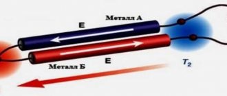
How does a "hot" alloy temperature sensor work in a flame?
The operating principle of a thermocouple is based on the physical phenomenon of thermoEMF. If you weld two conductors from different metals at one point and heat one of them and cool the other, a potential difference will appear at the ends.
In a thermocouple for a gas boiler, the outer surface of the junction head acts as a hot conductor, and the inner surface acts as a cold conductor. Heat is removed from it through a copper conductor. The temperature difference between outside and inside can reach several hundred degrees.
The voltage across the thermocouple when the gas burner is burning depends on the alloys and metals used in the junction. The most sensitive ones based on platinum group metals produce up to 50 mV for a long time. Sensors based on non-ferrous metals give 17-25 mV.
The temperature sensor is not immersed directly into the flame front. This cannot be done, since when the temperature sensor comes into contact with a hot gas flame, all parts will heat up to a high temperature, and the thermoEMF effect will disappear.
Therefore, they place the thermocouple at a distance of 3-4 cm from the igniter. This will ensure heating of the hot junction and normal cooling of the copper tube. Thermocouples are also installed in solid fuel heating boilers. For example, in the Lemax model the temperature sensor is installed above the grate.
Ring thermocouples.
| Marking | Meaning |
| TC403 | Series |
| J | Thermocouple type J (Fe-Co) |
| K | Thermocouple type K (Cr-Al) |
| T | Thermocouple type T (Cu-Co) |
| 4 | D - hole for countersunk screw M4 |
| 5 | D - hole for countersunk screw M5 |
| 6 | D - hole for countersunk screw M6 |
| … | Lead length, mm (standard value 1000 mm) |
| Code | Type | Lead length, mm |
| 100114 TEF 13 | Fe-CuNi type J | 2000 |
| 100115 TEF 13 | Fe-CuNi type J | 2500 |
| Code | Type | Lead length, mm |
| 100134 TEF 75 | Fe-CuNi type J | 2000 |
Advantages and disadvantages
It would seem, why install an additional device in a gas boiler if there is already a heat sensor on the heat exchanger. As soon as the temperature of the copper walls and water rises by ten degrees, the automation will understand that gas fuel combustion occurs as normal. But it's not that simple.
Positive aspects of using a temperature sensor at a junction of two metals
The first and most important advantage of a thermocouple is its simple design and extreme reliability of the device. If the burner of a gas boiler is regularly maintained and adjusted, the combustion sensor can last 20-25 years.
Another plus is the slight inertia of the device. The thermocouple is activated within 20-25 seconds from the moment the flame appears or disappears. There have been attempts to simplify the design of a gas boiler and transfer the functions of the combustion front temperature sensor to a temperature sensor. But it turned out that the heating or cooling time of the sensor spiral is an order of magnitude longer than that of a thermocouple. Accordingly, a dangerously large amount of gas and air manages to accumulate in a gas boiler; the firebox could simply explode.
Disadvantages of using a thermocouple
There are few negative sides. The durability of the sensor depends on the quality of the gas, the completeness of fuel combustion and the intensity of soot deposition on the surface of the junction. If the gas is contaminated with volatile metal carbonyls and vapors of heavy petroleum products, then the head of the junction becomes covered with a whitish or carbon coating.
Other disadvantages:
The thermocouple cannot be overhauled or restored. Therefore, if it fails, there is no other way out but to change the thermocouple in the gas boiler. And preferably the same model.
The part is subject to short circuiting. The causes are unknown, but it is believed to be due to condensation building up inside the copper tube.
Angle thermocouples.
| Code | Length L, mm | Type | Lead length, mm |
| TC00040180 | 12 | Fe-CuNi type J | 900 |
| TC00040185 | 20 | Fe-CuNi type J | 900 |
| Marking | Meaning |
| TC405 | Series |
| J | Thermocouple type J (Fe-Co) |
| K | Thermocouple type K (Cr-Al) |
| T | Thermocouple type T (Cu-Co) |
| … | Lead length, mm (standard value 1000 mm) |
| Code | Type | Lead length, mm |
| 106985 TEF 15 | Fe-CuNi type J | 2000 |
| Code | Type | Lead length, mm |
| 100124 TEF 21 | Fe-CuNi type J | 2000 |
| Code | Type | Lead length, mm | |
| 100125 TEF 55 | Fe-CuNi type J | 1100 | |
| 204453 TEF 55 | Fe-CuNi type J | 2000 | |
| Code | Type | Lead length, mm |
| 100132 TEF 68 | Fe-CuNi type J | 2000 |
| 266165 TEF 68 | Fe-CuNi type J | 2000 |
Thermocouple in a gas control system
There are two options for operating the combustion front sensor. The first is used in modern boilers equipped with electronic automation for monitoring and controlling the heating process. As a rule, the contact from the thermocouple is connected to the ignition unit. The voltage from the thermoEMF supplied to the board opens an electronic switch based on a thyristor or transistor. And that, in turn, opens the gas supply solenoid valve.
When the boiler is turned on, for 20-25 seconds, until the junction has warmed up, the electronic key is held open by a capacitor. If no voltage is supplied to the key from the thermocouple, the capacitor discharges, the valve closes, and the gas supply stops.
The second option is used in old floor-standing gas boilers without electronic components. Switching on is performed by pressing a button and mechanically unlocking the magnetic valve. If the gas burner is ignited and a thermoEMF appears on the thermocouple, then the generated voltage blocks the valve in the open position.
Angle temperature sensors with screw-in nipple.
| Code | Type | Lead length, mm |
| 100108 TEF 12 | Fe-CuNi type J | 2000 |
| 106500 TEF 12 | Fe-CuNi type J | 3000 |
| 206012 TEF 12 | Fe-CuNi type J | 3500 |
| 272242 TEF 12 | Fe-CuNi type J | 2000 |
| 114748 PWF 12 | — | 2000 |
| 204481 TEF 12 FF | Fe-CuNi type J | 2000 |
| Code | Type | Length L, mm | Lead length, mm |
| 100091 TEF 1 | Fe-CuNi type J | 60 | 2000 |
| 100093 TEF 1 | Fe-CuNi type J | 100 | 2000 |
| 100094 TEF 1 | Fe-CuNi type J | 150 | 2000 |
| 100270 PWF 1 | — | 60 | 2000 |
| Code | Type | Lead length, mm |
| 100108 TEF 12 | Fe-CuNi type J | 2000 |
| 106500 TEF 12 | Fe-CuNi type J | 3000 |
| 206012 TEF 12 | Fe-CuNi type J | 3500 |
| 272242 TEF 12 | Fe-CuNi type J | 2000 |
| 114748 PWF 12 | — | 2000 |
| 204481 TEF 12 FF | Fe-CuNi type J | 2000 |
Angle thermocouples with screw-in nipple.
| Code | Type | Lead length, mm |
| 100133 TEF 74 | Fe-CuNi type J | 2000 |
| Code | Type | Lead length, mm |
| 205421 TEF 101 | Fe-CuNi type J | 2000 |
| 108205 TEF 101 | Fe-CuNi type J | 2000 |
| Code | Type | Lead length, mm |
| 100268 TEF 104 | Fe-CuNi type J | 2000 |
Clamp thermocouples.
| Marking | Meaning |
| TC404 | Series |
| J | Thermocouple type J (Fe-Co) |
| K | Thermocouple type K (Cr-Al) |
| T | Thermocouple type T (Cu-Co) |
| … | Lead length, mm (standard value 1000 mm) |
| Code | Type | Lead length, mm |
| TC00240000 | Fe-CuNi type J | 900 |
| Code | Type | Diameter, mm | Lead length, mm |
| 267323 TEF 19 | Fe-CuNi type J | 40 | 2000 |
| 257416 TEF 19 | Fe-CuNi type J | 48 | 3000 |
| Code | Type | Fitting size, mm | Lead length, mm |
| 267323 TEF 19 | Fe-CuNi type J | 40 | 2000 |
| 257416 TEF 19 | Fe-CuNi type J | 48 | 3000 |
Advantages and disadvantages of the Chromel-Kopel thermocouple
The Chromel-Kopel thermocouple is distinguished by its simplicity and reliability of design, and a relatively high degree of temperature measurement accuracy. Due to the fact that Chromel and Copel thermoelectrode wire has excellent thermoelectric properties, low inertia and high heat resistance, the thermocouple can be used in a wide variety of fields and environments. In addition, thermocouple wire has a low cost, which is important from an economic point of view for consumers. The only drawback of this type of thermocouple is its sensitivity to deformation, which, however, does not have any effect on the accuracy and quality of measurements.
Clamp temperature sensors.
| Code | Type | Diameter, mm | Lead length, mm |
| 100143 TEF SP | Fe-CuNi type J | 20-32 | |
| 100144 TEF SP | Fe-CuNi type J | 23-35 | |
| 100145 TEF SP | Fe-CuNi type J | 25-40 | 2000 |
| 100146 TEF SP | Fe-CuNi type J | 32-50 | 2000 |
| 100147 TEF SP | Fe-CuNi type J | 40-60 | 2000 |
| 100148 TEF SP | Fe-CuNi type J | 50-70 | |
| 100149 TEF SP | Fe-CuNi type J | 60-80 | 2000 |
| 100150 TEF SP | Fe-CuNi type J | 70-90 | 2000 |
| 100151 TEF SP | Fe-CuNi type J | 80-100 | 2000 |
| 100152 TEF SP | Fe-CuNi type J | 90-110 | |
| 209332 TEF SP | Fe-CuNi type J | 40-60 | 3000 |
| 257095 TEF SP | Fe-CuNi type J | 16-25 | 3000 |
| 227313 TEF SP | — | 32-50 | 2000 |
| 256552 TEF SP | — | 60-80 | 3000 |
Cylindrical thermocouples.
| Marking | Meaning |
| TC400 | Series |
| J | Thermocouple type J (Fe-Co) |
| K | Thermocouple type K (Cr-Al) |
| T | Thermocouple type T (Cu-Co) |
| 1 | One thermocouple |
| 2 | Two thermocouples |
| 4; 6; 8; | D—thermoelement diameter, mm |
| 50; 100; 150; 200 | L—thermoelement length, mm |
| … | Lead length, mm (standard value 1000 mm) |
| Code | Type | Lead length, mm |
| 204441 TEF 14 | Fe-CuNi type J | 2000 |
Possible malfunctions and methods for eliminating them
Despite the fact that the design of the temperature sensor is simple and does not contain complex, breakable elements, the thermocouple can also be the reason for regular shutdowns of the gas burner.
The check begins with a boiler startup test. If the gas supply is blocked a few seconds after starting the automation, then the first thing to do is short-circuit the contacts on the pressure switch. The traction sensor is located in the automation control circuit, like the temperature sensor, so it must be excluded at the time of testing.
Lack of reliable contact
Often the burner is blocked for simple reasons. For example, the fitting nut has become unscrewed, or the surface of the contact pad has become dirty. You need to unscrew the fitting, wipe the threads and contact pad with alcohol, check the condition of the insulating gasket and screw the fitting nut back on.
Contamination or oxidation of the junction surface
The junction temperature is always 100-150 ℃ lower than that of the flame front. Therefore, during operation, the surface becomes overgrown with plaque, due to which the accuracy of the thermocouple is significantly reduced. Organic dirt is washed off with white spirit and acetone, everything else is removed with a brush with bronze bristles.
Burnout
Identified by the presence of microscopic cavities and areas of burnt metal. Sometimes damage can be determined by placing a copper tube in water and blowing hard. Air bubbles will appear. In this case, the thermocouple in the gas boiler must be replaced with a new one.
Make sure that the thread markings on the replacement fitting match those of the old thermocouple.
Incorrect position
When servicing the burner, it is necessary to remove the side lining, thermal insulation, spark plug and thermocouple. Often the situation ends with the sleeve being installed below the level of the igniter. Accordingly, the amount of heat leading to the junction decreases significantly, and the response time of the thermocouple increases multiple.
Therefore, before disassembling the gas burner, it will be useful to take a couple of photos with your phone camera. Such a safety net will help place the ignition elements in the correct position.
The thermocouple for a gas boiler has been and remains the main element of the safety system. If it fails, it is better to replace it with an analogue, without experimenting with models from gas stoves, ovens or speakers.
How to check the thermocouple of a boiler, stove, column: video.
Share your experience, whether you had to repair a thermocouple or replace it with sensors from other models of gas boilers. How successful was this replacement? Save the article to bookmarks and share with friends on social networks.
Cylindrical thermal sensors with bayonet connector.
| Code | Type | Diameter, mm | Lead length, mm |
| 100097 TEF 4 | Fe-CuNi type J | 8 | 2000 |
| 100099 TEF 4 | Fe-CuNi type J | 8 | 3000 |
| 100100 TEF 4 | Fe-CuNi type J | 8 | 5000 |
| 213286 TEF 4 | Fe-CuNi type J | 8 | 6000 |
| 100138 TEF 4 | Fe-CuNi type J | 6 | 2000 |
| 272237 TEF 4 | Fe-CuNi type J | 8 | 2000 |
| 207858 TEF 4 | Fe-CuNi type J | 8 | 3000 |
| 100275 PWF 4 | — | 8 | 2000 |
| 107383 PWF 4 | — | 8 | 2000 |
| 223361 PWF 4 | — | 6 | 2000 |
| Code | Type | Diameter, mm | Lead length, mm |
| 100101 TEF 4A | Fe-CuNi type J | 8 | 2000 |
| 112616 TEF 4A | Fe-CuNi type J | 6 | 2000 |
| 215795 TEF 4A | Fe-CuNi type J | 8 | 2000 |
| 100102 TEF 4A | Fe-CuNi type J | 8 | 3000 |
| 114951 PWF 4A | — | 8 | 2000 |
| Code | Type | Diameter, mm | Lead length, mm |
| 100120 TEF 16 | Fe-CuNi type J | 8 | 2000 |
| 100121 TEF 16 | Fe-CuNi type J | 8 | 3000 |
| 206236 TEF 16 | Fe-CuNi type J | 8 | 4000 |
| 2145871 TEF 16 | Fe-CuNi type J | 8 | 5000 |
| 100265 TEF 16 | Fe-CuNi type J | 6 | 1500 |
| 100139 TEF 16 | Fe-CuNi type J | 6 | 2000 |
| 210072 TEF 16 | Fe-CuNi type J | 6 | 3000 |
| 243328 TEF 16 | Fe-CuNi type J | 8 | 2000 |
| 100276 PWF 16 | — | 8 | 2000 |
| 108981 PWF 16 | — | 8 | 2000 |
Cylindrical thermocouples with bayonet connector.
| Code | Type | Lead length, mm |
| 100103 TEF 4B | Fe-CuNi type J | 2000 |
| Code | Type | Lead length, mm |
| 100105 TEF 11 | Fe-CuNi type J | 2000 |
| 215797 TEF 11 | Fe-CuNi type J | 3000 |
| 256682 TEF 11 | Fe-CuNi type J | 2000 |
| Code | Type | Lead length, mm |
| 249165 TEF 16B | Fe-CuNi type J | 2000 |
| 300334 TEF 16B | Fe-CuNi type J | 2000 |
| 107625 TEF 16B | Fe-CuNi type J | 3000 |
| Code | Type | Lead length, mm |
| 115706 TEF 16FF | Fe-CuNi type J | 2000 |
| Code | Type | Lead length, mm |
| 100123 TEF 20 | Fe-CuNi type J | 2000 |
| Code | Type | Lead length, mm |
| 100269 TEF 90 | Fe-CuNi type J | 2000 |
Cylindrical thermocouples with screw-in nipple.
| Marking | Meaning |
| TC004 | Series |
| J | Thermocouple type J (Fe-Co) |
| K | Thermocouple type K (Cr-Al) |
| T | Thermocouple type T (Cu-Co) |
| 1 | One thermocouple |
| 2 | Two thermocouples |
| 1; 1,5; 2; 3; | D—thermoelement diameter, mm |
| 50; 100; 150; 200 | L—thermoelement length, mm |
| … | Lead length, mm (standard value 1000 mm) |
| Marking | Meaning |
| TC402F | Series |
| J | Thermocouple type J (Fe-Co) |
| K | Thermocouple type K (Cr-Al) |
| T | Thermocouple type T (Cu-Co) |
| 1 | One thermocouple |
| 2 | Two thermocouples |
| WITH | Rod size: D=6mm, L=15mm |
| D | Rod size: D=6mm, L=30mm |
| WITH | Rod size: D=8mm, L=10mm |
| … | Lead length, mm (standard value 1000 mm) |
| Marking | Meaning |
| TC402M | Series |
| J | Thermocouple type J (Fe-Co) |
| K | Thermocouple type K (Cr-Al) |
| T | Thermocouple type T (Cu-Co) |
| 1 | One thermocouple |
| 2 | Two thermocouples |
| WITH | Rod size: D=6mm, L=15mm |
| D | Rod size: D=6mm, L=30mm |
| WITH | Rod size: D=8mm, L=10mm |
| … | Lead length, mm (standard value 1000 mm) |
| Code | Type | Lead length, mm |
| 107142 TEF 3 | Fe-CuNi type J | 2000 |
| Code | Type | Lead length, mm |
| 100128 TEF 57 | Fe-CuNi type J | 1100 |
| Code | Type | Lead length, mm |
| 100131 TEF 60 | Fe-CuNi type J | 2000 |
| Code | Type | Lead length, mm |
| 100137 TEF 94 | Fe-CuNi type J | 500 |
Connection nuances and verification
The verification procedure must be performed if the boiler starts up unstable, or if the electronic ignition unit unexpectedly switches to a continuous start-stop cycle. In the latter case, claims are often made unreasonably about the contacts on the thermocouple. In reality, the compensating capacitor of the ignition unit is to blame.
Be sure to check the new thermocouple. To do this, just connect the multimeter probes to the central contact (+) and the copper tube (-). Set the measurement limit to 1 V or 0.1 V, heat the junction with a candle or gas lighter. There should be at least 18 mV on the screen.
The old thermocouple on a boiler with AOGV can be checked without dismantling the device:
- unscrew the fitting nut of the AOGV block;
- light a papillon;
- connect the probes and take readings.
This method allows you to take the most accurate data. The multimeter should show at least 25-28 mV.
Pay attention to the position of the sleeve with the junction head. It should stand vertically, and the igniter flame should flow around only the upper 3 mm of the temperature sensor. Any other options lead to overheating or underheating of the device.
Thermal resistances.
| Marking | Meaning |
| TR800 | Series |
| P | Thermal resistance Pt100(standard) |
| N | Thermal resistance Ni 100 |
| 1 | One thermal resistance |
| 2 | Two thermal resistances |
| 2 | 2 wire resistance |
| 3 | 3 wire resistance |
| 4 | 4 wire resistance |
| 4; 6; 8; | Thermoelement diameter, mm |
| 30; 50; 100; 200 | Rod length |
| … | Lead length, mm (standard value 1000 mm) |
| Marking | Meaning |
| TR801 | Series |
| P | Thermal resistance Pt100(standard) |
| 1 | One thermal resistance |
| 2 | Two thermal resistances |
| 2 | 2 wire resistance |
| 3 | 3 wire resistance |
| 4 | 4 wire resistance |
| C | Rod dimensions ∅6×15 mm |
| D | Rod dimensions ∅6×30 mm |
| F | Rod dimensions ∅8×10 mm |
| … | Lead length, mm (standard value 1000 mm) |
Measurement speed
The dynamic response of the sensor can be important if the process temperature changes rapidly and the control system needs to provide rapidly changing input signals. A primary sensor installed directly into the process line will be faster than a primary sensor with a thermowell.
It is important to note that if no thermowell is used, the sensing element is exposed to the process environment and cannot be replaced without interrupting the flow, which often requires shutting down the process and draining the process system. Design guidelines in most plants do not allow the use of sensors without thermowells. Such installations are much less safe from the point of view of possible depressurization of process units, they are subject to more frequent failures of primary converters due to exposure to adverse process conditions, and they often require costly process shutdowns to replace a failed primary converter. The use of protective sleeves solves this problem.
But if a thermowell is used, it is obvious that the reaction time increases (response speed decreases) due to the increase in the thermal mass of the assembly. The key to optimizing performance is to reduce mass while maintaining sufficient physical strength to withstand process pressures and fluid flow forces. Smaller diameter thermowells provide faster performance because less material needs to be heated and cooled. It is also important to install the primary converter correctly to achieve high performance. The sensor must be long enough so that its end touches the bottom of the thermowell to ensure good thermal conductivity. The diameter of the primary sensor must also be such that it fits tightly into the protective sleeve and the air gap between the primary sensor and the protective sleeve is minimal. In addition, performance is improved by using a spring-loaded sensor and filling the voids in the sleeve with thermally conductive filler. The characteristics of the medium being measured also affect the performance, especially its flow rate and density. Fast-moving media transmit heat and changing temperature better than slow-moving media, and denser media (liquids) are better conductors of heat than low-density media (gases).
A comparison of the performance of temperature measurement systems using a thermocouple without thermowell or a thermowell-less RTD in a flowing water system showed that the grounded end of the thermocouple has a response speed approximately 2 times faster than a spring-loaded RTD sensor. When measuring in air flow, the TC operates somewhat faster than a thermocouple.
However, these advantages are greatly reduced, if not eliminated, when the sensor is installed in a thermowell. The mass of the thermowell is so large compared to the mass of the primary converter that it clearly has a dominant effect on system performance.
When using a 6 mm (1/4 inch) diameter sensor in a water temperature measurement system, the performance of the thermocouple and RTD is approximately the same, and when using a 3 mm diameter sensor, the thermocouple is slightly faster than the RTD. When measuring air temperature, the performance of thermocouples and RTDs is approximately the same when using both 3 mm (1/8 inch) and 6 mm sensors.
Since very few processes use sensors without thermowells for measurement, the inherent speed advantage of thermocouples is greatly negated. A thoughtful designer selects the best sensor for a given system based on many other factors, and does not rely on the misleading statements that are so often heard: “thermocouples are always faster than RTDs.”