When coordinating the parallel operation of transformers at electrical supply facilities, it often becomes necessary to check phase rotation.
I would like to tell you one case that touches on the issues of phase rotation in a network with three phases and an example of incorrect phasing, equipment and methods for solving this problem.
Direct and reverse phase rotation
Three-phase alternating current is graphically represented by three phases in the form of alternating sinusoids on the X-axis, shifted relative to each other by 120°. The first sine wave can be represented as phase A, the next sine wave as phase B, shifted 120° relative to phase A, and the third phase C, also shifted 120° relative to phase B.
Read also: How to calculate compound interest
Graphic display of phase shift for 120° three-phase network
If the phases have the order ABC, then this sequence of phases is called direct alternation. Consequently, the order of the SVA phases will mean reverse alternation. In total, three direct alternations of phases ABC, BCA, CAB are possible. For reverse phase rotation, the order will look like CBA, BAC, ACB.
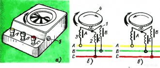
You can check the phase rotation of a three-phase network using a phase indicator FU - 2. It is a small case on which there are three clamps for connecting three phases of the network, an aluminum disk with a black dot on a white background and three windings. Its operating principle is similar to that of an asynchronous electric motor.
If you connect the phase indicator to three phases and press the button on the housing, the disk will begin to rotate in one direction. When the rotation of the disk coincides with the arrow on the body, then the phase indicator shows direct phase rotation; rotation of the disk in the opposite direction indicates reverse phase rotation.
Read also: What does “log in bed” mean?
Electrical circuit of the phase indicator FU-2
In what cases is it necessary to know the order of phase rotation? Firstly, if the house is connected to a three-phase network and an induction electric meter is installed, then direct phase rotation must be observed on it. If such an electric meter is connected incorrectly, it may self-propel, which will give incorrect readings in the direction of increasing electricity consumption.
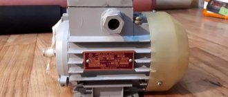
Also, if asynchronous electric motors are used in the house, the direction of rotation of the rotor will depend on the order of phase alternation. By changing the phase sequence on an asynchronous electric motor, you can change the direction of rotation of the rotor in the desired direction.
When is a phase indicator really necessary?
Phase advance angle determinants occupy large quantities on the shelves of electrical stores, both domestic and foreign models. But few electricians know how to determine that very advance angle and why it is needed at all.
A good, high-quality phase indicator is necessary when searching for phase rotation in order to ensure that the electric motor rotates in the correct direction. For example, when you turn on a water pump in a well, which can either transport it up or uselessly rotate the impeller blades attached to the electric motor, thereby consuming excess electricity.
Another good example that defines the importance of a phase indicator as a device: connecting an induction meter. If the phases are mixed up, then after installation the meter will continue to rotate the disk even when the load is turned off. When the device operates this way, the user will face additional costs, which can be eliminated by making a high-quality phase indicator with your own hands.
Why do you need to consider phase order?
The sequence of alternations plays a significant role in such situations:
- When connected in parallel, a number of devices (transformers, generators and other electrical machines) can be connected in parallel operation to increase the reliability of the system or to provide a greater power reserve. But, in case of incorrect connection, a short circuit will occur due to the connection of opposite phases.
- When connecting a three-phase meter - since its operation is based on the coincidence of phases with the corresponding terminals of the device, then if the connection is not correct, a failure and spontaneous movement may occur in the absence of any load. Because of this, such a connection of the electric meter will lead to the need for the consumer to pay for kilowatts that he did not consume.
- When the engine is turned on, the sequence of phases in the network determines the direction of rotation of the engine for the electric machine. In the absence of correct phasing, the direction of movement of the elements mechanically connected to the rotor will also change. This could result in a disruption of the technological process or a threat to the lives of personnel.
In order to prevent other mismatches, in practice, an interleaving check is performed and protection is installed.
A short introduction
A story about the installation of electrical equipment, namely two oil transformers, caught my eye. The work was completed successfully. As a result, there was the following power supply scheme. Actually the transformers themselves, input switches, sectional disconnectors, two bus sections. According to the installers, the commissioning work was completed successfully. They started switching on both transformers for parallel operation and got a short circuit. Naturally, the installers claimed that they had checked the phase rotation from both sources and everything matched. But not a word was said about phasing. But in vain! Now let's take a closer look at what went wrong.
What is phase alternation
It is known that a three-phase network consists of opposite phases. They are called ABC. According to theory, we know that the phase sinusoids are shifted relative to each other by one hundred and twenty degrees.
There are six different alternating orders, either reverse or direct. Reverse - CBA, ACB, BAC, direct - CAB, BCA, ABC.
To check the phase rotation order, use a phase indicator. Let's look at the method of checking with a phase indicator.
Operating procedure
The work is carried out in the following order by a licensed RTN electrical laboratory:
- checking the absence of voltage on the equipment being put into operation;
- the cable is disconnected from the busbars;
- one of the conductor cores is grounded;
- the insulation resistance of the conductor cores relative to the ground is measured;
- the conductor is marked, the resistance of which relative to the ground will be zero;
- phasing of the remaining cable cores is performed;
- the cable is connected to the switchgear according to the marking;
- a dialing operation is performed;
- phasing is performed under voltage. The check is carried out between the phases of the same name and the others. If there is no voltage between like phases, but there is voltage between opposite phases, then such a cable is put into operation, and therefore the switchgear.
The Perestroika MSK company has all the necessary permits and specialists who will perform the service of checking the phasing of switchgear and electrical equipment in the shortest possible time at the best prices in Moscow and Moscow Region. The customer is issued a document certifying the quality of the work performed.
Complex phase indicator
If assembling a phase indicator has become a challenge for a novice electrician, then using the diagram below, you can mount a device whose operation does not require a connection to the neutral conductor in the network. It should be immediately clarified that the manufacture of such a device will only be possible for a certain circle of specialists; it requires skill in working with a soldering iron and circuit boards.
The circuit is quite heavy, but it has all the necessary nominal values of the elements; you just need to make a few useful comments:
- The K561LP2 chip can be replaced with CD4030BE.
- Instead of the K561TM3 trigger, use the CD4042BE.
- Transistors KT3107A are replaced with models KT3107 or KT361, which are similar in their effect.
- The circuit uses diodes of the KD105V, KD105G, KD209B models.
- Any model can be used as LEDs, the main thing is to have the appropriate glow color.
- Extraordinarily precise assembly, which gives quick results when determining phasing.
- Checking the angle between phases takes a few seconds.
- No connection to the “zero” bus is required.
- When installed correctly, the device is durable and completely safe.
Unfortunately, there are some drawbacks to this DIY device. Firstly, the circuit is quite complex and most likely it will be very difficult for a novice electrician to install it correctly. Secondly, the cost of all elements can be quite high and it is cheaper to purchase an industrial device.
What is phase rotation?
Phase alternation should be understood as the sequence in which the voltage increases in each of them. In all three-phase circuits, the voltage is a sinusoidal curve. In each line the voltage differs by 120º from the others.
Rice. 1. Voltage in three-phase network
Tags
The phasing check is subject to the phasing control is carried out. Checking the phasing of the distribution. Checking the phasing of the electric. For phasing, checking the phasing consists of phase imbalance. Checking the phasing of the distribution. Checking the phasing of the distribution phase rotation in voltage control.
tube grounding indicator
Peculiarities
To reduce the likelihood of phase overload, the load is distributed evenly across phases. Failure to comply with this condition, as well as burnout of the “zero” conductor or its poor contact, will lead to a difference in voltage on the phase conductors, up or down.
Thus, converted single-phase power (220 V) will lead to malfunction of electrical consumers connected to it. This will happen due to the fact that some devices will receive an increased voltage (240-270 V), while others will receive a reduced voltage (160-200 V).
Important! If the load is unevenly distributed across phases, on meters that are not sensitive to distortions, there will be an increased consumption of electricity.
Conditions
There are certain conditions for parallel operation of transformers. There are 5 points in total. Switched on devices operate correctly under the following conditions:
- Phasing. The fulfillment of this condition by transformers is mandatory. Otherwise, a short circuit will occur. The secondary circuit currents allow phasing to be performed. The phases of the connections are coordinated on the low and high voltage sides.
- The voltage on the windings of the secondary and primary coils when connected must be different. This condition is met in compliance with the insulation features. The transformation coefficient of all elements of the system must be identical. Connecting the device is allowed if the deviation of the indicator does not exceed 0.5%.
- The short circuit voltage is the same for all units. This helps the windings perform their intended functions. Loop resistance increases at high short circuit voltages. By increasing its level for a low-power unit, you can get an overload. For normal operating conditions of the system, when standards are met, the deviation between the short circuit indicators of devices does not exceed 10%.
- It is allowed to turn on a parallel connection with identical windings corresponding to each other. If this condition is not met, equalizing currents are generated by operating devices. A phase shift is observed.
- The power of the equipment should not differ by 3 times. This is an important condition for the correct operation of the system. Otherwise, a powerful device increases the load on subsequent devices. Low-power units will be overloaded. Connecting such devices is prohibited by safety regulations.
Following the listed conditions, stable, efficient operation of power equipment is ensured. The safety and reliability of the system is increased.
What is phase alternation?
As you know, in a three-phase network there are three opposite phases. Conventionally, they are designated as A, B and C. Remembering the theory, we can say that the phase sinusoids are shifted relative to each other by 120 degrees. So, there can be six different alternation orders in total, and they are all divided into two types - direct and reverse. The following order is considered direct alternation - ABC, BCA and CAB. The reverse order will be CBA, BAC and DIA, respectively.
To check the order of phase alternation, you can use a device such as a phase indicator. We have already talked about how to use the phase indicator. Let's look specifically at the sequence of checking with the FU 2 device.
A more complex do-it-yourself phase indicator
For electricians who want to use more complex devices in a three-phase circuit, there is another scheme:
As can be seen from the presented diagram, a larger number of elements will be required here, and the assembly will be more complicated. But with proper installation, the output is provided with a high-quality and reliable phase indicator, which is also completely made by hand.
Items required for work:
- LED HB5d-448ABC-A - with green light. Replacement with LED type AL307 is allowed.
- LED HB5d-434FY-C - with yellow light. Replacement with LED type AL307 is allowed.
- 2 diodes KD209A. It is possible to replace elements with KD209B or KD209V diodes.
- 2 resistors with a resistance of 47 kOhm each. The power characteristic is insignificant, but it is better to take resistors rated at 0.125 W.
- Triac optocoupler MOS3063. It is possible to replace the element with an optocoupler MOS3062, MOS3082, MOS3083.
- A small piece of wire with a cross-section of 1 mm² for internal installation of the circuit.
- 3 pieces of wire with a cross section of 1.5 mm².
- Small breadboard.
- Plastic case.
Protection against alternation violation
To protect electrical equipment from incorrect rotation, a phase control relay is used in practice. This relay is configured to operate the engine or other device when it is connected directly. If due to some malfunction or incorrect connection the alternation is disrupted, the three-phase relay will immediately turn off the device. His work is based on the analysis of three-phase currents and voltages and subsequent monitoring of these parameters.
The connection can be made through current transformers or directly, depending on the model and voltage class of the network. Such protection has found wide application when connecting induction-type meters, electrical machines and other high-precision equipment.
What is it for?
Phase and voltage control relay is a device that is necessary when connecting equipment to a system with three phases, as well as in situations where it is important to maintain correct alternation
In practice, the product is used when equipment is frequently transferred, when changing the phasing may cause damage or incorrect operation.
A striking example is a screw-type compressor, the incorrect connection of which and switching on for more than five seconds leads to breakdown of an expensive product.
The phase and voltage monitoring relay allows you to identify the following problems:
- Break of any phase;
- Increase or decrease in voltage above (below) a given level;
- Phasing violation (phase connection order);
- Break of “zero”;
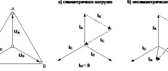
- Asymmetry of I and U (here we are talking about phase imbalance, when the angle between the vectors is significantly more or less than 120 degrees).
The schematic diagram of the device is shown below.
Some relays provide the ability to change the settings for the upper and lower limits U, as well as T (time) of operation.
As a rule, the output contact group of the relay is “dry”. In this case, there are two options available - normally closed and open. Some models have elements that operate on the induction principle.
Causes of the phenomenon
There are several reasons for this action to occur. The main reason when imbalance occurs is considered to be incorrect and uneven load distribution in the internal electrical network, when one phase receives an overload. As a result, the second and third ones will work with a significant underload.
In a network where there is only one phase, the load can also increase. This occurs when a large number of household appliances are powered. Then the imbalance becomes noticeable, as the power drops and the devices stop working.
Due to the fact that household appliances begin to work incorrectly, this can lead to their breakdown. As a rule, motors are considered the weak point in most devices in this case. That's why they fail. You can check where there is misalignment using a special device (current clamp), which will help determine on which circuit there is an overload.
The three-phase network has a solidly grounded neutral. It is this that equalizes the uneven distribution of voltage in the electrical circuit. But if the zero is broken, one phase takes over the role of the neutral. Then the voltage on it can reach up to 380 volts, and on the rest it will be 127 volts and lower.
How to check?
Checking can be done in several ways. The feasibility of choosing one or another option depends on the parameters of the electrical network and the problems that need to be solved. So the alternation can be recognized using a phase indicator, megohmmeter, multimeter or by the color of the cable insulation. Consider each option in more detail.
Using a phase indicator
According to the principle of operation, the phase indicator can be compared with a conventional asynchronous motor. Let us consider as an example the most common model of a phase indicator - FU-2.
Figure 3: Schematic diagram of the operation of FU-2
As you can see in Figure 3, the phase sequence indicator has three windings that are connected to the same phases in the network or device. Between the windings there is a rotating rotor P, which drives the phase indicator disk D.
In practice, after connecting the corresponding wires to the phase indicator terminals, the worker presses the K button, which closes the circuit of the windings. Depending on the order of phase alternation, disk D will begin to rotate clockwise or counterclockwise.
On the device itself there is an arrow indicating direct alternation. If, when the button is pressed, the disk rotates in the same direction as shown by the arrow, then this three-phase load is direct interleaved. If the disk starts to spin in the opposite direction from the arrow, then the phase sequence is reversed. It should be noted that this device is not able to determine which phase is on which wire, it can only determine the order of their alternation.
Using a megohmmeter
As one of the methods for testing conductors, a device for measuring resistance - a megohmmeter - is widely used.
Rice. 4: Testing the cable with a megaohmmeter
Look at Figure 4; to implement such a scheme, you will need to disconnect the cable from the network and from the consumer. At the same time, at one end of the cable, the phases are alternately connected to ground Z, just like the metal sheath of armored cables. On the other side, a megohmmeter M is connected, one of the terminals of which is grounded, and the second is alternately connected to each of the phases. On the one where the megohmmeter shows zero resistance, there will be one wire.
Appropriate markings are installed at the ends of the wire of the same name. The disadvantage of this method of dialing is the large amount of labor costs. Since each core is grounded one by one, after which a test is performed. In this case, responsible employees must be installed at both ends of the cable. Communication must be ensured between them to coordinate actions and prevent voltage from being applied to workers.
By color of core insulation
If any device has a connection with multi-colored wires, then the phasing of the equipment can be done by color. To determine the location of the same voltages of certain phases, it is necessary to get to each cable core. If each wire has insulation of different colors, then by comparing them with the place of connection to the transformer or switchgear, you can determine where each phase is located.
The disadvantage of this method is false color marking, since the cable manufacturer does not always provide the same color for each core along the entire length of the wire. Therefore, it is still recommended to ring and mark it first.
Using a multimeter
For this method, a regular multimeter is used. It is most relevant in situations where it is necessary to include two adjacent devices in parallel operation and their buses are located nearby.
Rice. 5: phasing with a multimeter
It is necessary to compare the phase voltages in adjacent lines; Figure 5 shows an example for phases A and A1. The switching equipment must be open. Before using a multimeter, the voltage class is set on it for the line on which the measurement will be made. The probes are brought to the phase terminals, while their insulation must provide protection from voltage, and dielectric gloves are put on the hands.
If, when connecting the probes to terminals A - A1, the arrow remains at the zero mark, this means that the phases are the same. If the arrow deviates by the amount of line voltage, you are measuring opposite phases.
Power cable lines
How to repair a heated electric floor with your own hands?
types of faults and sequence of work 1.8.37. Power cable lines with voltage up to 1 kV are tested according to clauses 1, 2, 7, 13, voltage above 1 kV and up to 35 kV - according to clauses 1-3, 6, 7, 11, 13, voltage 110 kV and above - in to the full extent provided for in this paragraph.
1. Checking the integrity and phasing of the cable cores. The integrity and coincidence of the phase designations of the connected cable cores are checked.
2. Insulation resistance measurement. Produced with a megohmmeter for a voltage of 2.5 kV. For power cables up to 1 kV, the insulation resistance must be at least 0.5 MOhm. For power cables above 1 kV, the insulation resistance is not standardized. The measurement should be made before and after testing the cable with increased voltage.
3. Test with increased voltage of rectified current. Power cables above 1 kV are tested with increased rectified current voltage.
The values of the test voltage and the duration of application of the normalized test voltage are given in table. 1.8.42.
Table 1.8.42. Rectified current test voltage for power cables.
| Cable insulation and grade | Test voltage, kV, for cables for operating voltage, kV | Test duration, min | |||||||
| 2 | 3 | 6 | 10 | 20 | 35 | 110 | 220 | ||
| Paper | 12 | 18 | 36 | 60 | 100 | 175 | 300 | 450 | 10 |
| Rubber brands GTSh, KSHE, KSHVG, KSHVGL, KSHBGD | – | 6 | 12 | – | – | – | – | – | 5 |
| Plastic | – | 15 | – | – | – | – | – | – | 10 |
During testing with increased voltage of rectified current, attention is paid to the nature of the change in the leakage current. The cable is considered to have passed the test if no breakdown occurred, there were no sliding discharges and leakage current shocks or its increase after it reached a steady value
The cable is considered to have passed the test if no breakdown occurred, there were no sliding discharges or surges of the leakage current or its increase after it reached a steady value.
4. Power frequency high voltage test. It is allowed to carry out for 110-220 kV lines instead of testing with rectified current; test voltage value: for lines 110 kV-220 kV (130 kV relative to ground); for lines 220 kV-500 kV (288 kV relative to ground). The duration of application of the normalized test voltage is 5 minutes.
5. Determination of the active resistance of the cores. Produced for lines 35 kV and above. The active resistance of the cable line conductors to direct current, reduced to 1 mm2 cross-section, 1 m length and temperature +20 °C, should be no more than 0.0179 Ohm for a copper conductor and no more than 0.0294 Ohm for an aluminum conductor.
6. Determination of the electrical working capacitance of the cores. Produced for lines 35 kV and above. The measured capacity, reduced to specific values, should not differ from the factory test results by more than 5%.
7. Measurement of current distribution along single-core cables. The unevenness in the distribution of currents on the cables should not be more than 10%.
8. Checking protection against stray currents. The operation of the installed cathodic protection is checked.
9. Test for the presence of undissolved air (impregnation test). Produced for oil-filled cable lines 110-220 kV. The content of undissolved air in the oil should be no more than 0.1%.
10. Testing of feeding units and automatic heating of end couplings. Produced for oil-filled cable lines 110-220 kV.
Table 1.8.43. Limit values of cable line oil quality indicators.
| Oil indicator | Standards for brand oil | |
| S-220 | MH-3 | |
| Electric strength, kV/cm, not less | 180 | 180 |
| Dielectric loss tangent at +100°С, %, no more | 0,005 | 0,008 |
| Acid number, mg KOH per 1 g of oil, no more | 0,02 | 0,02 |
| Degree of degassing, %, no more | 0,5 | 1,0 |
11. Monitoring the condition of the anti-corrosion coating. Produced for steel pipelines of oil-filled cable lines 110-220 kV.
12. Checking oil characteristics. Produced for oil-filled cable lines 110-220 kV. Sampling should be done from all elements of the line. Samples of S-220 grade oil taken after 3 days. after filling, must meet the requirements of table. 1.8.43.
Samples of MH-3 oil, taken from low and high pressure lines 5 days after filling, must meet the requirements of Table. 1.8.43.
13. Ground resistance measurement. Produced on lines of all voltages for terminations, and on lines 110-220 kV, in addition, for metal structures of cable wells and make-up points.
How to determine zero and phase without instruments
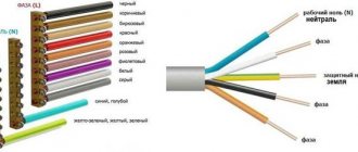
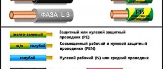
According to the PUE (Electrical Installation Rules), each wire that has its own functional purpose has its own specific color marking:
- the phase wire has insulation in black, white, brown (the most commonly used) colors and their many shades;
- the neutral wire has blue insulation with any shades of it;
- the earth is insulated with yellow-green stripes.
If the regulations were strictly observed, then there would be no problems with determining where the phase is, where the zero is, and where the ground is. In order to make it easier to navigate switching diagrams, phase, zero and ground designations are introduced on many electrical devices. All conductors are designated in accordance with state standards:
- L - this Latin letter designates the phase;
- N - this sign is used to find the neutral wire;
- PE - this combination of letters has always denoted land.
However, the visual method has some subjectivity; it is not always possible to accurately determine the correct color of the conductor insulation. In addition, not all electricians adhere to regulatory documents when carrying out electrical installation work. In old buildings, there is no need to talk about any standards for color marking of wiring.
Therefore, this method of finding phase and zero without instruments exists with a high degree of conditionality; it does not have a 100% guarantee. However, it is the only real way among others, such as using raw potatoes, to determine phase and zero without instruments. To obtain a reliable result, it is better to use data on the compliance of the wires with phase, neutral or grounding, tested using an indicator screwdriver or a multimeter.
Principles of checking phasing
This operation is performed before connecting 2 or more lines that operate independently in parallel operation. Also from an updated generator, after a major overhaul, during which the scheme for connecting the stator to the network could have changed. It is imperative to check the identity or color of the phase conductors. After all, they will need to be connected later.
This operation:
- Aimed at preventing errors when connecting installation lines in parallel.
- It allows you to correctly check all contacts.
- The correct connection of current-carrying cables connected to the device is checked.
The coincidence of identical currents along the line is checked, namely the absence of an angular shift. Only when positive results are obtained during phasing, generators or transformers operate in parallel and are connected for simultaneous operation.
Alternation indicator tests
The layout according to the diagram was tested on a universal board. Works without problems. The total cost of the radio components was about 200 rubles (you must admit that you cannot buy a ready-made, high-quality phase rotation indicator for this money).
When performing installation, be sure to make jumpers with well-insulated wire (such as Teflon) and consider coating the board with insulating varnish. Be sure to place everything in a plastic case. Despite the described actions, we are still dealing with high voltage three-phase networks and must be very careful! For a phase voltage of 220 V, the peak value is 320 V, and for a phase-to-phase voltage of 400 V, the peak value is 560 V, respectively.
The sequence of manufacturing a simple phase indicator
Attention! Self-manufacturing of circuits here and below is extremely dangerous for life, as it can lead to injury from high voltage, therefore such production can only be performed by people who have special education and approvals!
There is a circuit for a simple phase indicator that can be used in a three-phase industrial network without fear of electric shock or damage to the device. The diagram is presented below:
To work you will need the following elements:
- 3 connecting terminals, made of the “crocodile” type.
- 2 resistors with a resistance of 10 kOhm and 18 kOhm.
- Diode type KD105V. It is possible to replace the element with a diode from the KD209 series.
- Thyristor type T112-25-10 (25A 1000V). It is possible to replace the element with VS-25TTS12-M3 (25A 1200V).
- Incandescent lamp, voltage 26 V and current 0.12 A.
- A small piece of wire with a cross-section of 1 mm² for internal installation of the circuit.
- 3 pieces of wire with a cross-section of 1.5 mm² of such length that it is enough to comfortably measure the phases with your own hands.
- Plastic case.
The sequence of installing the electrical circuit of the phase indicator with your own hands:
- Connect the elements of a diode, a thyristor, two resistors and an incandescent lamp using soldering according to the above diagram.
- Secure the soldered parts in the plastic case. You can use epoxy glue, but not on the elements themselves, which can heat up during operation.
- Use a thin drill to drill 3 holes in the body and run 3 identical pieces of wire with a cross section of 1.5 mm² into them - these will be measuring probes. Secure the wires with epoxy - since the conductors are insulated, excessive heating is not a problem here.
- Attach crocodiles to the ends of the measuring probes. For greater reliability, they can be soldered.
- In the top cover of the plastic case, drill or cut a hole for a socket for a signal lamp. The cartridge is securely secured to the inside of the housing using epoxy glue.
- Secure the top housing cover with four small self-tapping screws.
- Checking the device on a line in which the phases are clearly located correctly.
This phase indicator has a significant advantage over expensive industrial models - simplicity. The cost of all elements (including consumables) required for assembly is very low and will not hurt your pocket. Any novice electrician, even those who picked up a soldering iron for the first time, can assemble and solder such a circuit.
The operating principle of the devices is very simple: phased lines turn on the lamp on the device body. Correct alternation - the lamp glows brightly, incorrect - very dim or does not glow at all. You can choose the simplest case of the device, but only from insulating plastic or any other material that does not allow electric current to pass through.