What is the excitation system in an alternator?
1. Excitation is a term used by electrical engineers to mean the creation of a magnetic field. The simple magnet used in this chapter to illustrate the operation of a generator is of course capable of creating a current in the windings of the generator, but a permanent magnet ceases to be permanent under the influence of vibration and heat.
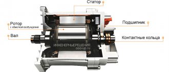
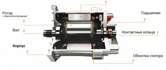
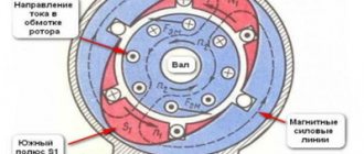
2. Typically, the rotor is made in the form of an electromagnet made of mild steel or iron, on which a coil is wound. A direct current is passed through the coil, inducing a magnetic field in the iron rotor. The strength of the magnetic field induced by such a cut depends on the strength of the current passed through the excitation winding, and this fact provides another advantage, since it allows you to regulate the emf in the stator windings of the generator.
3. If the rotor coil is wound with a non-iron core as shown in Fig. 3.13(a) , then you get a magnet with one pair of poles N ( North - northern) and S ( South - southern).
Rice. 3.13(a). A simple electromagnet.
Due to the large distance between the poles, magnetic force lines will be highly scattered in space. Now let's stretch the poles of the magnet towards each other, so that there is only a small gap between them (see Fig. 3.13 ( b )).
Rice. 3.13(6). Let's bend the ends of the electromagnet to concentrate the field.
And finally, we will make the magnetite poles in the form of a set of teeth that fit into each other, but without contact (see Fig. 3.14 ). We will get in total a long narrow gap between the poles N and S , through which the magnetic field will “leak” outward. When the rotor rotates, this “leakage” will cross the stator windings and induce an emf in them. 4. In order for the magnetic field of the rotor not to change direction, its coil must be powered by direct current of the same polarity. Current is supplied to the rotating coil through carbon brushes and commutator rings.
To power the rotor winding with direct current, two methods are used: self-excitation and excitation from an external source (usually from a battery).
Rice. 3.14. Toothed generator rotor.
The rotor magnetic field, necessary to create the electromotive force of the stator winding of any generator, is created by direct current flowing through the field winding (OB). The excitation system is designed to supply the OF, which largely determines the reliability of the operation of synchronous generators. In this regard, the following basic requirements are imposed on the excitation system:
- 1) reliable power supply with direct current OB in any modes, including during accidents in power systems;
- 2) stable regulation of the excitation current when the generator load changes;
- 3) required speed;
- 4) forcing excitation, i.e. ensuring a rapid increase in the excitation current, up to approximately double the value;
- 5) rapid damping of the excitation magnetic field during operational disconnections of the generator from the network.
Depending on the energy source used to power the excitation windings, excitation systems are divided into groups:
- 1) electric machine excitation using a direct current generator;
- 2) electric machine excitation using an alternating current generator with the conversion of this current into direct current;
- 3) self-excitation by converting part of the alternating current electrical energy of the generator into direct excitation current energy.
Electric machine excitation systems, where the energy source is a direct current generator, i.e. exciter have been used for a long time for most generators. Usually they were on the same shaft as the generator and were driven by the same turbine as the generator itself. Such a system is called direct. If the exciter is driven by a separate motor, the system is usually called indirect.
In the domestic generator industry, as a rule, a direct excitation system is used, which has a lower cost and greater reliability.
The increase in the power of turbo and hydrogen generators, and therefore the required power of exciters, initiated the need to replace DC generators with electric machine excitation systems using alternating current generators that do not have any power limitations. To convert alternating current into direct current, mercury rectifiers were previously used, which later gave way to controlled and uncontrolled semiconductor converters based on diodes, thyristors, and transistors. Semiconductor converters are more reliable, and in general the system with alternating current generators is faster, allowing for a high level of excitation (up to four times the rated excitation voltage with a constant excitation system time of less than two hundredths of a second). The widespread introduction of excitation systems with controlled converters was carried out for the first time in the world in our country. Subsequently, the transition to such systems was carried out abroad.
Contents of delivery:
The excitation system kit includes:
- Excitation system cabinet;
- Protective resistance (inside the excitation system cabinet);
- Conversion transformer;
- A set of technical documentation in Russian: passport, technical description and operating instructions, a set of diagrams and drawings, description of service software (on electronic media);
- Electronic media with documentation and service software;
- Spare parts kit (composition according to the Customer’s technical requirements).
*At the Customer's request, the delivery set can be changed. The exact delivery set is indicated in the product passport.
Independent excitation of generators
Independent excitation of generators has become most widespread. The main advantage of this method is that the excitation of a synchronous generator does not depend on the mode of the electrical network and is therefore the most reliable.
On generators with a power of up to 100 MW inclusive, as a rule, a direct current generator connected to the shaft of a synchronous generator is used as an exciter (Fig. 2).
Fig.2. Schematic diagram of independent electric machine excitation of the generator
The exciter itself is excited using a self-excitation circuit (the excitation winding of the LGE exciter is powered by the armature of the exciter itself). The exciter excitation is controlled manually by a shunt rheostat RR installed in the LGE circuit, or automatically by an AVR excitation regulator.
The disadvantages of an excitation system with a direct current generator are determined mainly by the shortcomings of the exciter itself. One of the disadvantages is the relatively low rate of increase in excitation, especially for exciters of hydrogenerators that have a low rotation frequency (V = 1-2 1/s).
Another disadvantage of the excitation system under consideration is typical for turbogenerators with a high rotation speed. It is caused by a decrease in the reliability of the DC generator due to vibration and difficult operating conditions of the brushes and commutator (switching conditions).
For turbogenerators with a power above 165 MW, the excitation power becomes so significant that it becomes difficult to produce a reliably operating DC generator at a rotation speed of 3000 rpm under switching conditions.
To reduce the rotation speed of the exciter in order to increase the reliability of its operation, sometimes the exciter is connected to the generator shaft through a gearbox. This system was used for a number of turbogenerators, including the TGV-300 and TVM-300 generators. The disadvantage of this excitation system is the presence of an additional mechanical transmission.
To excite large generators in the USSR, excitation systems with semiconductor rectifiers are used.
In an excitation system using semiconductor rectifiers, an auxiliary generator is coupled to the turbine generator shaft, the voltage of which is rectified and supplied to the turbine generator rotor winding (Fig. 3).
Fig.3. Schematic diagram of high-frequency excitation of a turbogenerator
A high-frequency inductor-type generator is used as an auxiliary generator. Such a generator does not have a winding on a rotating rotor, which increases its reliability in operation. The increased frequency (500 Hz) makes it possible to reduce the size and increase the speed of the excitation system.
The inductor high-frequency exciter generator VGT has three excitation windings located together with a three-phase alternating current winding on a stationary stator. The first of them, LGE1, is connected in series with the rotor winding of the main generator LG and provides the main excitation of the VGT. By connecting LGE1 in series with the rotor winding of the main generator, a sharp increase in the excitation of the VGT is ensured during short circuits in the power system due to an inrush current in the rotor. Windings IGE2 and LGEЗ receive power from the high-frequency exciter GEA through rectifiers. The sub-exciter (high-frequency machine 400 Hz with permanent magnets), like the auxiliary generator of the VGT, is connected to the shaft of the turbogenerator.
Current regulation in LGE2 and LGE3 is carried out using two devices - respectively, electromagnetic type regulators ARV (automatic excitation regulator) and UBF (non-contact excitation boosting device).
The ARV device ensures that the generator voltage is maintained in normal operating mode by changing the current in the LGE2 winding. The UBF device provides initial excitation of the generator and its boost when the voltage drops by more than 5%.
The high-frequency excitation system provides kf=2 and the rate of increase of the excitation voltage is not less than 2 1/s.
Fig.4. Schematic diagram of independent thyristor excitation of generators
A schematic diagram of the independent thyristor excitation (TH) system is shown in Fig. 4. On the same shaft as the generator G there is a synchronous auxiliary generator GE, which has a three-phase winding with taps on the stator. In the circuit shown in Fig. 4, there are two groups of thyristors: working VS1 and forcing VS2. On the AC side they are connected at different voltages, on the DC side they are connected in parallel. Excitation of the generator in normal mode is provided by the working group of thyristors VS1, which are opened by applying the appropriate potential to the control electrode.
Excitation system design:
Structurally, the excitation system is made in one metal cabinet with one-sided service with a degree of protection IP22 (on request - IP31, IP54).
The excitation system cabinet contains:
- Power circuit protection devices;
- Control circuit protection devices;
- Microprocessor excitation regulator (for two-channel systems - two independent excitation regulators);
- Thyristor converter (for systems with power section redundancy - two independent thyristor converters);
- Starting resistances with a thyristor switch;
- Power backup circuits for control circuits;
- Controls and indications on the front door of the cabinet.
Excitation system protection
The excitation system provides the following types of protection:
- From loss of excitement;
- From an increase in generator stator voltage in idle mode;
- From reducing the generator stator voltage frequency in idle mode;
- From exceeding the exciter excitation current limit;
- From a malfunction of the thyristor rectifier control channel;
- From short circuits at the converter output;
- From excitation current overload;
- From reducing the insulation resistance of the excitation winding.
The parameters and range of settings are given in the technical documentation for the excitation system.
The activation of protections is displayed on the display, recorded in the controller’s event log, recorded on the output relays and transmitted to the protection circuit in the form of a discrete signal or via a digital interface.
Network synchronization (optional)
By agreement with the Customer, the exciter can be equipped with a synchronization device with the network, which provides:
- Automatic synchronization
- Manual precise synchronization
Automatic and manual fine synchronization operate both with local and remote control. Additionally, to ensure synchronous connection of the generator to the network, a synchronism control relay is built into the synchroscope; the output signal of this relay is connected in series with the signal to turn on the mains switch.
Telecontrol (optional)
The pathogen has the ability to be remotely controlled. Telecontrol – control carried out by operational personnel from a remote control point node or by dispatch personnel from a dispatch center using a coded signal transmitted over communication channels.
By means of remote control, the excitation system can receive the following commands:
- Increase the setting;
- Decrease the setting;
- Turn on excitation;
- Disable excitation (quenching);
- Enable regulation based on Ug (generator voltage);
- Enable regulation by Q;
- Switching regulators from primary to backup and vice versa;
- Reset protections;
- Enable offline mode;
- Enable manual controller mode;
- Disable manual mode (enable automatic mode) of the regulator.
If necessary, the scope of teams is agreed upon with the Customer at the detailed design stage. Telecontrol can be organized using specialized network cards using the MODBUS RTU, MODBUS TCP/IP, PROFIBUS DP protocols (RS485 and Ethernet interfaces) as agreed with the Customer.
The excitation system provides all the necessary measurements and information exchange with the station-level automated process control system and interaction with unit-level systems, including: measurement and generation of signals for the current and voltage of the generator stator, excitation circuit, as well as generator frequency at the main control room and on its own front panel, while communication with the station's automated process control system and aggregate level is provided via a serial interface RS485 and (or) Ethernet. The type of protocol, type of interface and the amount of necessary information transmitted to the automated control system must be negotiated separately with each Customer at the detailed design stage.
Discrete signals
Discrete signals about the state of technological equipment are output in the form of binary signals “0” “1”. In this case, voltages of alternating current 220V, direct current 220, 48, 24V can be used as signal “1”. The input/output channels of analog and discrete signals are galvanically isolated from each other and relative to the ground.
Excitation control system
The excitation control system carries out automated control of excitation system devices, providing control functions for excitation system equipment.
The generator excitation system is made according to single-channel or two-channel (with 100% redundancy of control systems and thyristor rectifiers) circuits. The power supply for the control circuits is backed up from an operational DC source of 220V and/or from the auxiliary network ~220V, depending on the design.
In two-channel systems, each regulator (ARV1 and ARV2) is a full-featured generator excitation control system, has its own set of analog sensors (with individual galvanic isolation), discrete inputs and outputs, and protection devices. If a working channel is damaged, an automatic, shock-free transition to a working regulator is carried out.
Each channel provides automatic and manual excitation control; switching between manual and automatic control modes is shockless. Switching modes (Automatic/Manual) is carried out using a key on the front panel of the cabinet (in local control mode) or from the main control room (in remote control mode). Also, the manual mode is switched on automatically when the voltage measuring circuits are lost and the backup channel is simultaneously unavailable. Regulation of the generator voltage, regardless of the number of the active channel and the regulation mode, is performed with one key on the front panel or main control room.
The control system consists of the following interconnected modules: 1. Two independent microprocessor excitation controllers DExS (for two-channel systems); 2. Communication module iCM; 3. Operator panel DExS.OP.CM3; 4. Power backup system for auxiliary needs.
Automatic excitation regulator DExS
The control system is a multiprocessor excitation control unit DExS, which implements direct digital control of the thyristor exciter. High-speed digital signal processors with an FPU unit (floating-point unit) are used.
Advantages of DExS:
- It is a monoblock built-in module that provides full functionality for controlling generator excitation. Includes a complete set of inputs/outputs:
- Analog inputs allow direct measurement of signals from basic sensors (stator and rotor current and voltage).
- 16 digital inputs and 16 digital outputs = 24V.
- SIFU - 6 amplifiers of thyristor control pulses.
- High accuracy of controller calculations due to the use of floating point numbers.
- High computing speed. All analog signals and the excitation controller are processed at a constant frequency of 10KHz.
- There are no tuning elements at all. All settings are stored in non-volatile memory and are duplicated many times with the function of automatically restoring a faulty block of settings from a backup copy.
- Additional removable key for backing up settings.
- Thyristor pulse amplifiers with valve conductivity control.
- Automatic phasing SIFU - works correctly with any phasing.
- Automatic continuous measurement of rotor insulation resistance in the range of 0-2000 kOhm in 62 Ohm steps.
- Built-in 10,000 samples per second oscilloscope for 32 channels (32 any selected 16-bit registers) with configurable auto-trigger scripts, number of pre- and post-samples. Used for commissioning and as an emergency oscilloscope. Emergency oscillograms are copied into non-volatile memory after the generator is stopped.
iCM Communication Module
Thanks to the iCM module, external data consumers (process control systems, instrumentation and control equipment, operator panel) two DExS controllers (for redundant systems) are represented as one device.
The iCM communication module provides the following services:
- Synchronization of settings of DExS regulators (DExS settings must be completely identical throughout the entire operation of the exciter).
- Two-way exchange of information between two DExS and external data consumers (operator panel, PLC). For access from the process control system, iCM is equipped with:
- Ethernet 10/100T Mbit, MODBUS TCP/IP protocol
- RS485 protocol MODBUS RTU
- Transfer of data “from” and “to” the instrumentation and automation chain from a centralized source, through:
- 2 inputs 4-20mA
- 2 outputs 4-20mA
- 12 discrete inputs = 24V
- 8 discrete outputs =24V 150mA
- Primary accumulation of statistical data and oscillography on a micro-SD card with a capacity of up to 4GB (8 days of continuous recording).
Operator panel DExS.OP.CM3
Panel devices provide operational information about the main parameters of the system, while being non-volatile indicators (do not require an additional power source). The operator panel increases information capabilities. The operator panel displays detailed information about the operation of the excitation system and generator, allows you to change settings, view event archives and statistics, and copy the necessary information to external storage devices.
Viewing statistics and waveforms from the event recorder is possible using the Ajuster software (via the interface) and the operator panel. The operator panel provides an advanced event registration service:
- recording waveforms and statistics on an SD card (can be removed for incident investigation);
- an oscillogram is a continuous recording for 30 days with a frequency of 100 records of all controller parameters per second;
- the oscillogram and statistics can be copied to a USB Flash disk or over the network to a disk on a remote server;
- access to files is possible via Ethernet using a secure SSH protocol;
- Using the operator panel, you can view the oscillogram of any event, within an arbitrarily specified time interval “before” and “after” the event.
Thyristor converters
The thyristor converter (rectifier) is made according to a bridge circuit: with a rated excitation current of up to 400A, thyristor modules are used, installed on coolers with natural air cooling; rectifiers over 400A are manufactured using tablet thyristors, which are cooled using a combined method.
The combined cooling method combines natural and forced cooling. A special thermal control module measures the temperature of thyristor assemblies at several points using digital temperature sensors and turns on the fans only when they heat up above a given set point and turns off the fans after cooling the assemblies to a given temperature.
In excitation systems with a backup thyristor converter, each thyristor rectifier has an automatic switch at the input and a disconnector in the DC circuit. Signals from the switch and disconnector are fed into the regulator and when the switching equipment is turned off (when the protection is triggered or manually), an automatic transition to the backup rectifier occurs.
Field blanking
The field suppression of generators up to 12.5 MW is carried out only by damping resistors, which are connected in parallel to the excitation winding with a triac switch (two back-to-back thyristors), which is controlled autonomously by a special board. The setting for turning on the damping resistances is selected by a DIP switch installed on the board. Before starting the generator and before applying the excitation current, the quenching circuit is forcibly turned on using a relay. This extinguishing circuit is built into the excitation system cabinet.
Power transformer
The thyristor rectifiers of the main and reserve channels are powered from a TE converter transformer, which can be connected to the generator buses using a self-excitation circuit or powered from a 0.4 kV source.