Synchronous electric motor device
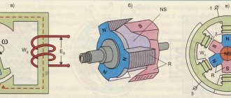
The structure of this type of unit is typical. The engine consists of:
- Fixed part (armature or stator).
- Moving part (rotor or inductor).
- Fan.
- Slip rings.
- Brush.
- Pathogen.
The stator is a core consisting of windings, which is enclosed in a housing. The inductor is equipped with DC electromagnets (poles). The inductor design can be of two types - salient-pole and non-salient-pole. The stator and rotor contain ferromagnetic cores made of special electrical steel. They are necessary to reduce magnetic resistance and improve the passage of magnetic flux.
The rotor speed in a synchronous motor is equal to the speed of the magnetic field. Regardless of the connected load, the rotor frequency remains unchanged, since the number of pole pairs of the magnetic field and the rotor are the same. Their interaction ensures a constant angular velocity, independent of the torque applied to the shaft.
Operating principle of a synchronous electric motor
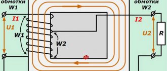
The most common types of such units are single-phase and three-phase. The operating principle of a synchronous electric motor is approximately the same in both cases. After connecting the armature winding to the network, the rotor remains stationary while direct current flows into the field winding. The direction of the electromagnetic torque changes twice during one voltage change. When the average torque value is zero, the rotor, under the influence of an external torque (mechanical impact), accelerates to a frequency close in value to the frequency of rotation of the magnetic field in the gap, after which the motor switches to synchronous mode.
In a three-phase device, the conductors are located at a certain angle relative to each other. An electromagnetic field rotating at a synchronous speed is excited in them.
Engine acceleration can be carried out in two modes:
- Asynchronous. The inductor windings are closed using a rheostat. The rotating magnetic field that occurs when the voltage is turned on crosses a short-circuited winding mounted on the rotor. Currents are induced in it and interact with the rotating field of the stator. Once synchronous speed is reached, the torque begins to decrease and is reduced to zero after the magnetic field is closed.
- With an auxiliary engine. To do this, the synchronous motor is mechanically connected to an auxiliary motor (DC motor or three-phase induction motor). DC current is supplied only after the motor has reached near synchronous speed. The magnetic field is closed and communication with the auxiliary motor is terminated.
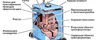
Constructive solution
Like any electric drive, synchronous motors (SM) are converters that convert electrical energy into mechanical work. They also belong to reversible mechanisms and can operate in generator mode. In this case, electrical equipment is not a drive for moving parts of production or engineering installations, but rather acts as a source of electricity. A striking example of such an application can be hydraulic or turbogenerators.
Similar to asynchronous motors, LEDs operate from an alternating current source and have two main working units - a stator and a rotor. The first has an absolutely identical design, is a stationary element of the device and is also known as an inductor or inductor wheel. Its main components:
- a housing with a box for electrical connections located on it;
- ball bearings designed to support the rotor unit;
- bearing support elements;
- a fan that removes heat during operation of the electric drive;
- protective casing separating the rotating fan from the housing.
The steel body of the inductor has a cylindrical shape and can be prefabricated or made from separate elements. In the inner part there is a steel core made up of individual strips about 0.5 mm thick. All plates are reliably isolated from each other. The outer strips have special grooves in which phase electrical circuits (windings) are located.
The design (one-piece or prefabricated) depends on the overall dimensions and, accordingly, the power of the electric motor. The stators of small mechanisms are made in the form of one-piece products; more powerful devices have a prefabricated structure. This decision was dictated by the difficulties of production, transportation, installation and repair. Inductors can also have different winding arrangements, including distributed or concentrated.
The second functional unit - the rotor - has individual design features, rotates and is a direct tool for transmitting mechanical energy to the driven working units. It is also called an anchor. It is the structure of the rotor unit that distinguishes electric drives of synchronous and asynchronous types. Depending on the load that the LED must absorb and, accordingly, its power parameters, the rotor mechanism, which includes a core, is designed in different ways. It could be:
- synchronous motor with permanent magnets (PMSM) on the armature unit, providing magnetoelectric excitation;
- an electric machine with electromagnets that provide electromagnetic excitation.
The first option is intended for low-power electric drives, the second - for electrical devices designed to withstand heavy loads.
Permanent magnets are made of hard magnetic materials (precision alloys) with high residual magnetic induction. Their characteristic feature is the ability to maintain a state of magnetization for a long time. Hard magnetic products come in different shapes and are autonomous sources (not consuming energy) of a magnetic field. Regarding the method of installing magnets, SDs are divided into electric motors with surface and built-in arrangement of magnetic elements.
Electromagnets, as the name suggests, are associated with electric current. This device consists of a ferromagnetic core and a winding, which, when energized, initiates the appearance of a magnetic flux around the core. The purpose of any electromagnet is to set in motion the moving part of the magnetic circuit. Such a tool is an anchor, which transmits mechanical forces to the working units of the equipment.
Generator mode
The peculiarity of synchronous machines to provide constant speed for a long time, as well as their reversibility, contributes to their greater widespread use as an alternating current generator. Power plants use turbogenerators, in which steam turbines and hydrogenerators driven by hydraulic turbines are used as the primary engine.
Turbogenerators are high-speed non-salient-pole units installed horizontally at thermal power plants. They are long with a relatively small diameter. Hydrogenerators are low-speed salient-pole installations located vertically at hydroelectric power plants. They have a large diameter with a relatively low height.
Generators are described by the following main characteristics:
- idle speed, which represents the dependence E0 = f (Iв);
- external, described by the function U = f (I);
- regulatory, characterized by the dependence Iв = f (I).
The rotor mechanism of magnetoelectric generators at low power is “star-shaped”, at higher loads it is “claw-shaped”. At significant power (from tens to hundreds of kilowatts), the design of generators becomes similar to the design of normal salient-pole synchronizers.
Control system
The drive machine is controlled by automated devices, which use frequency converters or servo drives. Also, the control function can be implemented by special control systems. The basis for choosing one method or another is always the task that the electric drive must perform. In practice, the following control methods are used:
- sinusoidal – divided into scalar and vector;
- trapezoidal - can be with or without feedback.
The scalar scheme refers to simple control methods. It is not optimal and is not suitable for tasks where the load changes, since there is a possibility of loss of controllability (out of synchronism). The vector method is divided into field-oriented and direct torque control. The first option can be implemented with or without a position sensor. Using a sensor and microcontroller, smooth and precise adjustment of the shaft position and the required speed characteristics of the SD with a large control range are achieved. The sensorless method is only possible for salient-pole electric drives.
Vector direct control has a simple circuit, good dynamic characteristics, a large control range and the absence of a position sensor. The disadvantages of this method include high torque and current pulsations.
The trapezoidal control scheme without feedback is one of the simplest control methods and has the same disadvantages as the scalar one. If there is feedback, there are two possible options: with or without sensors. The first method involves installing three built-in Hall sensors, which provide determination of the angular position of the shaft. The second requires a more powerful control system and is not suitable for low speed operation.
V-shaped characteristics
V-shaped characteristics represent the dependence of the armature current I
and the power factor
cosj
of the motor from the excitation current i
in
at constant values of the armature winding voltage U
and
its frequency f
and
constant output mechanical power P2
.
These characteristics reflect an important feature of synchronous motors
- the ability to regulate their reactive power and cosj
.
Let's consider the V-shaped characteristics of motors using the example of a non-salient pole machine. The necessary explanations are given using simplified vector diagrams of a synchronous motor presented in Fig. 12.3.
If we accept losses in the winding and armature steel, mechanical and additional losses as constant, then at P
2= const the power supplied to the armature winding is also constant,
P
1=
mUIcosj
= const, and, therefore, the active component of the armature current is also constant -
I
a=
Icosj
= const.
Therefore, in the vector diagram (Fig. 12.3), the end of the armature current vector I
at different values of the excitation current
i
in slides along straight AB.
For each value of I,
the value
of iв
can be determined from the current equation of a synchronous machine, reflecting the MDS equation.
Thus, iв
d represents the resulting MMF in the gap
Fd
on the excitation current scale,
I¢
is the MMF of the armature reaction
F¢
a on the excitation current scale or the reduced armature current.
The excitation current is directly proportional to the MMF F
in the excitation winding.
Value iв
d can be determined from the resulting emf
E
d of the armature winding induced by the resulting magnetic field of the air gap.
If we neglect for simplicity the leakage resistance x
sa= 0 and the active resistance
r
a= 0, then and, trace -
Rice. 12.3. Simplified vector diagrams of a synchronous motor
specifically, i
вd »
const
.
The vector, like the vector of the resulting flow in the gap, is 90° ahead. The vector coincides in direction with the armature current, and its end slides along the straight line A'B', parallel to the line AB, since I'
is directly proportional to the armature current.
In Fig. 12.3 vector diagrams of currents are plotted for four points V
-shaped characteristic and the excitation currents for the corresponding armature currents were obtained.
For point 1 in Fig. 12.3, a vector voltage diagram was also constructed according to the equation, where E
is the emf induced in the armature winding by the field of the excitation winding;
x
c is synchronous inductive reactance.
Advantages and scope
Thanks to the development of the production of precision alloys, it has become possible to design and successfully use PMSMs with magnetoelectric excitation technology. Compared to devices using electromagnets, the simpler design of this type of electrical equipment has led to a number of practical advantages:
- increased reliability;
- increase in efficiency due to the absence of excitation losses;
- reduction in size and weight at higher frequencies and low power;
- Possibility of autonomous use as an increased frequency generator of low and medium power.
PMSMs have not become widely used as electric drives due to poor starting properties. The limited use is also caused by their increased cost compared to other types of LEDs. This is due to the complexity and additional costs of manufacturing and processing hard magnetic materials with high coercivity. Therefore, such electric drives are produced at low power for use in industrial automation systems and instrument making.