In the SI system of units, inductance is measured in henry, abbreviated as Hn. A circuit has an inductance of one henry if, when the current changes by one ampere per second, a voltage of one volt appears at the terminals of the circuit. In addition to a brief theoretical overview, this review presents an inductance calculator for converting to decimal prefixes in the SI system.
Self-induction phenomenon
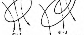
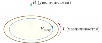
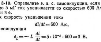
If the current flowing through a conducting circuit changes in magnitude, then the phenomenon of self-induction occurs. In this case, the magnetic flux through the circuit changes, and an emf, called self-induction emf, appears at the terminals of the current-carrying frame. This EMF is opposite to the direction of the current and is equal to:
ε=-∆Ф/∆t=-L*(∆I/∆t)
It is obvious that the self-induction emf is equal to the rate of change of the magnetic flux caused by a change in the current flowing through the circuit, and is also proportional to the rate of change of the current. The proportionality coefficient between the self-inductive emf and the rate of change of current is called inductance and is denoted L. This quantity is always positive, and has an SI unit of 1 Henry (1 H). Fractional fractions are also used - millihenry and microhenry. We can talk about inductance of 1 Henry if a change in current by 1 ampere causes a self-inductive emf of 1 Volt. Not only the circuit has inductance, but also a separate conductor, as well as a coil, which can be represented as many series-connected circuits.
The inductance stores energy, which can be calculated as W=L*I2/2, where:
- W – energy, J;
- L – inductance, H;
- I – current in the coil, A.
And here the energy is directly proportional to the inductance of the coil.
Important! In engineering, inductance is also a device in which an electric field is stored. The real element closest to this definition is the inductor.
The general formula for calculating the inductance of a physical coil is complex and inconvenient for practical calculations. It is useful to remember that inductance is proportional to the number of turns, the diameter of the coil and depends on the geometric shape. Also, the inductance is affected by the magnetic permeability of the core on which the winding is located, but is not affected by the current flowing through the turns. To calculate the inductance, each time you need to refer to the given formulas for a specific design. So, for a cylindrical coil, its main characteristic is calculated by the formula:
Inductance and capacitance in an alternating current circuit
Changes in current, voltage, etc. d.s. in an alternating current circuit occur with the same frequency, but the phases of these changes are, generally speaking, different. Therefore, if the initial phase of the current strength is conventionally taken as zero, then the initial phases of voltage and e. d.s. respectively will have some values of ϕ and ψ. Under this condition, the instantaneous values of current, voltage, etc. d.s. will be expressed by the following formulas:
i = Im sin ωt
u = Uм sin (ϕ + ωt),
e = Ɛm sin (ψ + ωt).
The circuit resistance, which causes irretrievable loss of electrical energy due to the thermal effect of current, is called active. This resistance for low frequency current can be considered equal to the resistance R of the same conductor to direct current and can be found using the formula:
R=(pl/S)(1 + at).
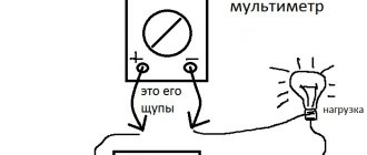
In an alternating current circuit that has only active resistance, for example in incandescent lamps, heating devices, etc., the phase shift between voltage and current is zero, i.e. ϕ = 0. This means that the current and voltage in such a circuit change in the same phases, and the electrical energy is completely spent on the thermal effect of the current.
Connection diagram and diagram
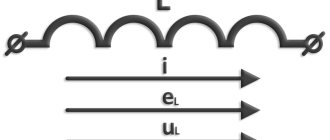
The inclusion of a coil with inductance L in an alternating current circuit manifests itself as an increase in the resistance of the circuit. This is explained by the fact that with alternating current the e is always active in the coil. d.s. self-induction, weakening the current. Resistance XL, which is determined by the phenomenon of self-induction, is called inductive resistance. Since e. d.s. self-inductance is greater, the greater the inductance of the circuit and the faster the current changes, then the inductive reactance is directly proportional to the inductance of the circuit L and the circular frequency of the alternating current ω:
ХL = ωL.
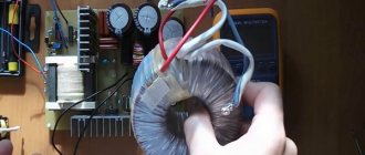
The effect of inductive reactance on the current strength in a circuit is clearly illustrated by the experiment shown in Fig. 26.6. When the ferromagnetic core is lowered into the coil, the lamp goes out, and when it is removed, it lights up again. This is explained by the fact that the inductance of the coil increases greatly when a core is introduced into it. It should be noted that the voltage across the inductive reactance is ahead of the current in phase.
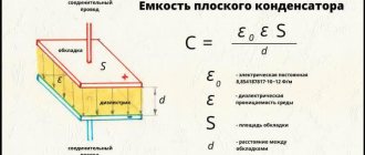
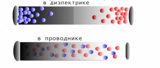
Direct current does not pass through the capacitor, since there is a dielectric between its plates. If a capacitor is connected to a DC circuit, then after charging the capacitor, the current in the circuit will stop.
Inductors
Let the capacitor be connected to an alternating current circuit. The charge on the capacitor (q=CU) changes continuously due to voltage changes, so alternating current flows in the circuit. The greater the capacitance of the capacitor and the more often it is recharged, i.e., the greater the frequency of the alternating current, the greater the current strength. The resistance caused by the presence of electrical capacitance in the alternating current circuit is called capacitive reactance Xc. It is inversely proportional to the capacitance C and the angular frequency ω;
Xc = 1/ωС
From a comparison of formulas (26.11) and (26.12) it is clear that inductors represent a very large resistance for high-frequency current and small resistance for low-frequency current, and capacitors - vice versa. The voltage across the capacitive reactance Xa lags in phase with the current. Inductive XL and capacitive XC resistances are called reactive. In the theory of alternating current, it is proven that when inductive and capacitive reactances are connected in series, the total reactance is equal to their difference:
It will be interesting➡ What is grounding in simple words
X = XL—XC
and has an inductive character for XL > Xc and a capacitive character for XL < Xc.
In conclusion, we note that the average active power of alternating current, showing how much energy per unit time is transferred by electric current to a given section of the circuit, is determined by the formula:
P = IU cos ϕ.
The power expended only on the thermal effect of the current is expressed by the formula:
P = I2R
To increase the active power of alternating current, you need to increase cos ϕ. (Explain why cos ϕ has the greatest value at XL=XC.)
Inductance
Series and parallel connection of inductors
Inductors can be connected in series or in parallel, resulting in a set with new characteristics.
Parallel connection
When the coils are connected in parallel, the voltages on all elements are equal, and the currents (variables) are distributed in inverse proportion to the inductances of the elements.
- U=U1=U2=U3;
- I=I1+I2+I3.
The total inductance of the circuit is defined as 1/L=1/L1+1/L2+1/L3. The formula is valid for any number of elements, and for two coils it is simplified to the form L=L1*L2/(L1+L2). Obviously, the final inductance is less than the inductance of the element with the smallest value
Serial connection
With this type of connection, the same current flows through a circuit made up of coils, and the voltage (alternating!) on each component of the circuit is distributed in proportion to the inductance of each element:
- U=U1+U2+U3;
- I=I1=I2=I3.
The total inductance is equal to the sum of all inductances, and will be greater than the inductance of the element with the largest value. Therefore, such a connection is used when it is necessary to increase the inductance.
Important! When connecting coils into a series or parallel battery, the calculation formulas are correct only for cases where the mutual influence of the magnetic fields of the elements on each other is excluded (by shielding, large distances, etc.). If an influence exists, then the overall value of the inductance will depend on the relative position of the coils.
Application in technology
Inductors are used:
Rice. 9. Inductors
- For noise suppression, ripple smoothing, energy storage, alternating current limitation, in resonant (oscillating circuit) and frequency-selective circuits; creating magnetic fields, motion sensors, in credit card readers, as well as in contactless credit cards themselves.
- Inductors (together with capacitors and resistors) are used to construct various circuits with frequency-dependent properties, in particular filters, feedback circuits, oscillating circuits and others. Such coils, accordingly, are called: contour coil, filter coil, and so on.
- Two inductively coupled coils form a transformer.
- An inductor, powered by a pulsed current from a transistor switch, is sometimes used as a high-voltage source of low power in low-current circuits when creating a separate high supply voltage in the power supply is impossible or economically impractical. In this case, high voltage surges appear on the coil due to self-induction, which can be used in the circuit.
- When used to suppress interference, smooth out electrical current ripples, isolate (high-frequency) different parts of the circuit, and store energy in the magnetic field of the core, an inductor is called an inductor.
- In power electrical engineering (to limit the current during, for example, a short circuit of a power line), an inductor is called a reactor.
- Current limiters for welding machines are made in the form of an inductance coil, limiting the current of the welding arc and making it more stable, thereby allowing for a more even and durable weld.
- Inductors are also used as electromagnets - actuators. A cylindrical inductor whose length is much greater than its diameter is called a solenoid. In addition, a solenoid is often called a device that performs mechanical work due to a magnetic field when a ferromagnetic core is retracted.
- In electromagnetic relays, the inductors are called relay windings.
- A heating inductor is a special inductor coil, the working element of induction heating installations and kitchen induction ovens.
By and large, in all electric current generators of any type, as well as in electric motors, their windings are inductor coils. Following the ancient tradition of depicting a flat Earth standing on three elephants or whales, today we could with greater justification assert that life on Earth rests on an inductive coil.
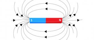
Rice. 15. Earth's magnetosphere
After all, even the Earth’s magnetic field, which protects all terrestrial organisms from corpuscular cosmic and solar radiation, according to the main hypothesis about its origin, is associated with the flow of huge currents in the liquid metal core of the Earth. In essence, this core is a planetary-scale inductor. It is calculated that the zone in which the “magnetic dynamo” mechanism operates is located at a distance of 0.25-0.3 Earth radii.
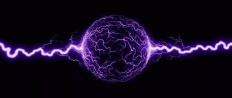
Rice. 7. Magnetic field around a current-carrying conductor. I
— current,
B
— magnetic induction vector.
Some practical issues and inductor designs
In practice, various designs of inductors are used. Depending on the purpose and area of application, the devices can be made in different ways, but the effects that occur in real coils must be taken into account.
Inductor quality factor
A real coil, in addition to inductance, has several other parameters, and one of the most important is the quality factor. This value determines the losses in the coil and depends on:
- ohmic losses in the winding wire (the higher the resistance, the lower the quality factor);
- dielectric losses in wire insulation and winding frame;
- screen losses;
- core losses.
All these quantities determine the loss resistance, and the quality factor is a dimensionless quantity equal to Q=ωL/Rloss, where:
- ω = 2*π*F – circular frequency;
- L – inductance;
- ωL is the reactance of the coil.
Units of inductance in CGS and related systems
In the Gaussian system of units and the SGSM system (these are variants of the SGSM system), a centimeter is a unit of measurement of inductance. The inductance ratio in these henry systems is given by the expression:
\[\left[L\right]=1\ cm=1nHn;;1\ Hn={10}^9cm.\]
Sometimes, to avoid confusion, the name abhenry is used for the centimeter as a unit of inductance.
In the SGSE system (an extension of the SGSE system), the unit of inductance is considered dimensionless or is called stathenry:
\[1stathenry\approx 8.987552\cdot {10}^{11}Gn.\]
Quality factor
Quality factor is the ratio between reactive and inductive (active) reactance.
Active is an indicator of the natural resistance of a material. Reactive occurs if the effective value of voltage, current or capacitance changes.
The following equation is used for measurement:
Q=2∙π∙f∙L/R,
Where:
- π – Pi number equal to 3.14;
- F – frequency;
- R – resistance.
A problem may arise with the concept of “frequency”, because Many people do not know what an oscillatory circuit is. This is some kind of circuit in which there is a coil.
Typically, an oscillating circuit consists of a power source, an inductive element and a capacitor. The frequency is determined using Thomson's formula (also known as the resonant frequency formula).
The higher the frequency indicator, the “higher quality” the coil is considered.
Representation of henry in other units of measurement - formulas:
Henry is expressed in terms of base and derived SI units as follows:
Gn = (kg m2) / (s2 A2)
Gn = V s / A
Gn = m² kg / Cl²
Gn = J / A²
H = Ohm s
Gn = Wb / A
where A is ampere, B is volt, Wb is weber, J is joule, C is coulomb, m is meter, Ohm is ohm, s is second, W is watt, kg is kilogram.