using a thyristor, which even a novice radio amateur can
assemble with his own hands
.
It can be used as a stand-alone device or in addition to an existing charger
, since the circuit implements several types
of protection
.
There is protection
, since without a connected battery there is no output voltage.
Also, the device will not fail if the battery is connected incorrectly; the transistor will open the thyristor only if the battery
.
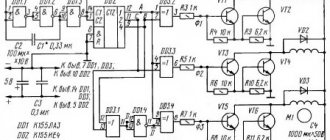
We take a ready-made transformer or wind it ourselves, with a power of 150-200 watts, a secondary winding with a voltage of 16-19 volts. Instead of the thyristor and transistor indicated in the diagram, you can put KU202 with any letter index and KT815, respectively. Resistor R4 is used to select the minimum charging switch-on voltage; the circuit
is designed for a 12-volt battery. Before turning on, be sure to check the correct installation. I recommend it, an excellent thing against errors.
If desired, you can add a voltmeter and an ammeter at the output of the circuit to the battery. The voltmeter is connected in parallel to the load, and the ammeter in series, through the “+” line.
I recommend making the diode bridge using D242 diodes
Click on image to enlarge
Analogs of thyristor KU 202
Foreign analogues of the KU202N thyristor are VTX32S100, H20T15CN, 1N4202. Foreign manufacturers do not produce devices with the same geometric dimensions as the KU202N, so you will need to change the location for mounting the device. It should also be taken into account that their parameters may differ slightly from the thyristor in question, for example, the average current may be 7.5 A.
In addition to foreign devices, you can use the Russian analogue - T112-10. Like KU202N, it has a metal body and an anode outlet for thread. However, its dimensions are smaller, so the installation location will still have to be changed.
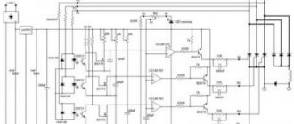
Schematic diagram of a 2 kW UPS
The mains voltage first passes through a noise filter and is then rectified and filtered using capacitors C4. To reduce the inrush current, a switch was connected in series with Re1 and R2. The relay and fan coil (regular, from the computer power supply) are powered by 12 V, obtained by reducing the 17 V voltage from the auxiliary source. Resistor R1 should be selected as such that the voltage across the said coil and fan is 12V. The auxiliary power supply was built based on the TNY267 m/s. Resistor R27 implements undervoltage protection for this power source - it will not start at a voltage below the peak of 220 V.
The UC3845 controller has a 50 kHz output signal and a maximum duty cycle of 47%. It is powered by a zener diode, which reduces the supply voltage by 5.6 V (with an output of 11.4 V), and also shifts the UVLO thresholds from 7.9 V (lower) and 8.5 V (higher) to 13.5 and respectively. 14.1 V. Therefore, the power supply will start operating at a voltage of 14.1 V, and will not go lower than 13.5 V, due to which the IGBT protection was obtained from non-saturating operation. This was initially not possible because the UC3845 thresholds were too low.
This circuit drives MOSFET T2, which in turn powers control transformer Tr2. The result was galvanic isolation and floating control. This transformer, through shaping systems with T3 and T4, controls the IGBT gates T5 and T6. These transistors switch the rectified mains voltage (325 V), powering the power transformer Tr1.
The voltage from the secondary winding of this transformer is then rectified using a rectifier connected in the transit system and smoothed by inductor L1 and capacitors C17. Voltage feedback is provided from the output to pin 2 of the UC3845. The voltage can be set using potentiometer P1. Galvanic isolation of the feedback is not required since the controller was connected to the secondary voltage side and isolated from the network. Current feedback was implemented using current transformer Tr3 and output to output 3 of the UC3845. The current limit threshold can be set using P2.
Transistors T5, T6, diodes D5, D5′, D6, D6′, D7, D7′ and the diode bridge must be placed on the radiator. Diodes D7, capacitors C15 and protective circuits R22 + D8 + C14 should be as close as possible to the IGBT. LED 1 indicates that the device is on, LED 2 indicates current limit mode or error. It will glow when the circuit is not in voltage regulation mode. In the stabilized state, output 1 of the UC3845 is 2.5 V, otherwise about 6 V. The LED signaling can be removed.
Parameters of thyristor KU 202
| Parameter | Designation | Unit | Thyristor type | |||
| KU202A | KU202B | KU202V | KU202G | |||
| Constant current in closed state | Iz. With | mA | 10 | 10 | 10 | 10 |
| Constant reverse current at Urev max | Iobr | mA | 10 | 10 | 10 | 10 |
| Unlocking constant control current | Iу. from | mA | 200 | 200 | 200 | 200 |
| Unlocking constant control voltage | Uу. from | IN | 7 | 7 | 7 | 7 |
| Open voltage | Uoc | IN | 1,5 | 1,5 | 1,5 | 1,5 |
| Non-latching constant control voltage | Uу. notes | IN | 0,2 | 0,2 | 0,2 | 0,2 |
| On time | ton | mks | 10 | 10 | 10 | 10 |
| Shutdown time | toff | mks | 150 | 150 | 150 | 150 |
| Maximum permissible parameters | ||||||
| Constant voltage when closed | Uz. with max | IN | 25 | 25 | 50 | 50 |
| Constant reverse voltage | Uar max | IN | — | — | — | — |
| Constant reverse control voltage | Uу. arr max | IN | 10 | 10 | 10 | 10 |
| Minimum forward voltage in closed state | Uz. with min | IN | — | — | — | — |
| Constant current in open state | Ioc min | A | 10 | 10 | 10 | 10 |
| Pulse current in open state | Ios. and min | A | 50 | 50 | 50 | 50 |
| Constant forward control current | Iу max | A | — | — | — | — |
| Pulse dissipated power of the UE | Ru. and max | W | — | — | — | — |
| Average power dissipation | Pav max | W | 20 | 20 | 20 | 20 |
| Maximum ambient temperature | Tmax | °C | +85 | +85 | +85 | +85 |
| Minimum ambient temperature | Tmin | °C | -60 | -60 | -60 | -60 |
| Parameter | Designation | Unit | Thyristor type | |||
| KU202D | KU202E | KU202ZH | KU202I | |||
| Constant current in closed state | Iz. With | mA | 10 | 10 | 10 | 10 |
| Constant reverse current at Urev max | Iobr | mA | 10 | 10 | 10 | 10 |
| Unlocking constant control current | Iу. from | mA | 200 | 200 | 200 | 200 |
| Unlocking constant control voltage | Uу. from | IN | 7 | 7 | 7 | 7 |
| Open voltage | Uoc | IN | 1,5 | 1,5 | 1,5 | 1,5 |
| Non-latching constant control voltage | Uу. notes | IN | 0,2 | 0,2 | 0,2 | 0,2 |
| On time | ton | mks | 10 | 10 | 10 | 10 |
| Shutdown time | toff | mks | 150 | 150 | 150 | 150 |
| Maximum permissible parameters | ||||||
| Constant voltage when closed | Uz. with max | IN | 120 | 120 | 10 | 10 |
| Constant reverse voltage | Uar max | IN | — | — | 240 | 240 |
| Constant reverse control voltage | Uу. arr max | IN | 10 | 10 | — | — |
| Minimum forward voltage in closed state | Uz. with min | IN | — | — | — | — |
| Constant current in open state | Ioc min | A | 10 | 10 | 10 | 10 |
| Pulse current in open state | Ios. and min | A | 50 | 50 | 50 | 50 |
| Constant forward control current | Iу max | A | — | — | — | — |
| Pulse dissipated power of the UE | Ru. and max | W | — | — | — | — |
| Average power dissipation | Pav max | W | 20 | 20 | 20 | 20 |
| Maximum ambient temperature | Tmax | °C | +85 | +85 | +85 | +85 |
| Minimum ambient temperature | Tmin | °C | -60 | -60 | -60 | -60 |
| Parameter | Designation | Unit | Thyristor type | |||
| KU202K | KU202L | KU202M | KU202N | |||
| Constant current in closed state | Iz. With | mA | 10 | 10 | 10 | 10 |
| Constant reverse current at Urev max | Iobr | mA | 10 | 10 | 10 | 10 |
| Unlocking constant control current | Iу. from | mA | 200 | 200 | 200 | 200 |
| Unlocking constant control voltage | Uу. from | IN | 7 | 7 | 7 | 7 |
| Open voltage | Uoc | IN | 1,5 | 1,5 | 1,5 | 1,5 |
| Non-latching constant control voltage | Uу. notes | IN | 0,2 | 0,2 | 0,2 | 0,2 |
| On time | ton | mks | 10 | 10 | 10 | 10 |
| Shutdown time | toff | mks | 150 | 150 | 150 | 150 |
| Maximum permissible parameters | ||||||
| Constant voltage when closed | Uz. with max | IN | 10 | 10 | 10 | 10 |
| Constant reverse voltage | Uar max | IN | 360 | 360 | 480 | 480 |
| Constant reverse control voltage | Uу. arr max | IN | — | — | — | — |
| Minimum forward voltage in closed state | Uz. with min | IN | — | — | — | — |
| Constant current in open state | Ioc min | A | 10 | 10 | 10 | 10 |
| Pulse current in open state | Ios. and min | A | 50 | 50 | 50 | 50 |
| Constant forward control current | Iу max | A | — | — | — | — |
| Pulse dissipated power of the UE | Ru. and max | W | — | — | — | — |
| Average power dissipation | Pav max | W | 20 | 20 | 20 | 20 |
| Maximum ambient temperature | Tmax | °C | +85 | +85 | +85 | +85 |
| Minimum ambient temperature | Tmin | °C | -60 | -60 | -60 | -60 |
Powerful power supply.
Sergei Nikitin.‘>
I once worked in a trolleybus depot repairing electrical equipment. Our workshop was located on the second floor of a building in the park. We repaired and tested trolleybus electrical and radio equipment. And so, in order to check the serviceability of powerful electrical equipment and trolleybus converters, the men carried heavy batteries from trolleybuses, and even to the second floor. Laziness, as they say, is the engine of progress, I can’t handle such things, and the men are pretty tired, and thanks to this, the idea was born to find a replacement for these activities and make a fairly powerful power supply with which it would be possible to check the performance of any trolleybus electrical equipment. I had a powerful power supply in the garage, and using the same scheme, I decided to assemble a similar device for the needs of the trolleybus fleet, which would be of help to me, and to the joy of the men.
This circuit is a powerful power supply, where thyristors are used as control elements. The entire power of this power supply is limited only by the power transformer and thyristors. If you install a more powerful transformer and thyristors, then the output current of this power supply will increase accordingly.
The power supply was assembled mainly from parts of decommissioned and disassembled office equipment and from what was found there. And there, in the trash, I found a ready-made transformer from an uninterruptible power supply UPS-1200, which produces 2x30 Volts, thyristors VS1 - VS2 T50 for 50A, you can use any ones with a current of at least 40A instead, and if the load current is planned to be less, then of course you can install thyristors with less current. Choke L1 was also found in radio junk from an unknown device, the magnetic circuit looked like from TSSh-160 (TSSh-170) and the window was completely filled with a winding, a wire with a diameter of 3 mm with a gap of 1.5-2.0 mm , quite a powerful looking throttle. If you don’t find a ready-made throttle, you can make it yourself. The core can be taken from any power transformer with a power of 100-120 W, preferably a W-shape (SH) and the winding can be wound with a wire with a diameter of 2.0-3.0 mm (a set of wires), or even both P and PL cores are suitable . You can wind a winding on them on one frame until the window is filled, or divide it into two frames and then connect the halves in series (beginning with beginning or end with end) and assemble a core with a similar gap. Transformer TV2 was taken from some kind of transistor radio receiver; this is a matching transformer. You can use any one of a similar purpose, or wind it yourself on a small core, according to the data available in reference books on transistor radios, Radio magazines or on the Internet. The minimum output voltage of the power supply was about 1.5V, the maximum under full load was 30 Volts. The power supply keeps it quite stable.
The power supply, as I said, works very stably. Transistor VT2 forms a “saw” for PWM operation, synchronized with the network through transistor VT1. It is advisable to select capacitor C7 according to the linear shape of the “saw” on it. I installed filter capacitors C11-C12 at 2200 uF 50 volts; the diagram shows their minimum capacity. At K140UD7, pulses are generated that already control the thyristors through a composite (Darlington) transistor VT3. Instead of K140UD7, you can install K140UD6, K140UD8 and almost any others that are suitable for the supply voltage and a load resistance of at least 2 kOhm. These microcircuits are not critical to the supply voltage, so as KS515 you can use any other zener diodes with a stabilization voltage from 12V to 15V (D814G, D814D, KS512) or imported ones. Transistors VT1-VT2 can be used of any corresponding structure, and instead of VT3 you can also use any Darlington of the corresponding structure, for example from old matrix printers, they are used there to control stepper motors.
You can try using a MOSFET with an N-channel instead of VT3, then any operational amplifier will do, the only thing you need is to reduce the capacitance C13 to 10nF, increase the resistor R12 to 100kOhm. Capacitor C8 ensures stable operation of thyristors at low load currents and smooth voltage supply after the power supply is connected to the network. I didn’t make a printed circuit board; I did all the mounting on a small board, to which I glued electrolytic capacitors and mainly used their terminals as mounting points.
This control circuit has also been used in car battery chargers. The output voltage of the secondary of the power transformer, then 2x15-18 volts will be enough, with the permissible current with which you plan to charge the batteries. Thyristors for the charger will be sufficient for 10-25 amperes and inductor L1 can be excluded from the circuit. For such purposes, I try to use wire resistors (R10) as a regulating resistor; they are more reliable, especially for the garage or where there are differences in temperature and humidity. The thyristors are mounted on an aluminum plate, which is used as a thyristor mount, as a contact, and as a heat sink.
Yes, if you need to wind up a matching transformer and don’t find it ready, then the thyristor control circuit can be made using this option.
In this case, there is no need to install a transformer. I took the most popular optocouplers from the 817 series, which are found in computer power supplies, and they controlled T122-25 thyristors. This scheme also worked quite well. Yes, I have not tested this circuit for operability with powerful thyristors and with old Soviet-made thyristors. I don't know how she will work with them. There, simply with a small output voltage, you need to keep the holding current and the control current too, otherwise periods are skipped chaotically and the transformer begins to twitch and click. In order for the thyristors to be normally open in this case (the required holding current flows through them), you can place a load resistor of appropriate power before the ammeter (in parallel with capacitors C11-C12), which would provide the required holding current for the thyristors at a minimum output voltage, and which would withstood the maximum output voltage. I didn’t do any protection in this power supply because I didn’t want to do a complicated one, and a simple one usually doesn’t have time to work. I just installed Sovdepov’s thyristors, which are much more reliable than transistors, and when you come across free thyristors, you can install more powerful ones with a reserve. Good luck in your creativity and all the best!
Brief classification of power sources for arc welding
As shown in the diagram below, arc welding power sources can be classified according to various criteria.
According to the first criterion, power supplies are classified according to the method of energy production: whether it is converted from the power supply network (as is the case with transformers, rectifiers and electronic power supplies) or generated by the power supplies themselves (as is the case with generators).
According to the second criterion, power sources are classified according to the method of converting electrical energy:
- by using transformers that convert the relatively high voltage of the power network into a lower voltage for welding with alternating current; — by using welding rectifiers, consisting of a transformer (to reduce the voltage of the power network) and a rectification unit to convert alternating current into direct current; — by using electronic power sources (for example, welding inverters); - by using welding converters consisting of a welding generator, the rotation of the rotor of which is provided by an electric motor; — by using welding units consisting of a welding generator, the rotation of the rotor of which is ensured by an internal combustion engine (strictly speaking, the unit converts not electrical energy, but mechanical into electrical energy).
The third classification feature is the method of obtaining energy: power sources can be dependent (all except units, since they receive energy from a stationary electrical network) and autonomous (units, since their generator is connected to an internal combustion engine).
According to the fourth criterion, power sources are classified in accordance with the method of regulating welding parameters. In transformers and rectifiers, this can be done using moving coils, moving magnetic shunts, sectioning the turns of the secondary winding and other methods.
The fifth classification feature is the type of welding current that is provided by power sources: alternating (AC), direct (DC) or both, both AC and DC (combined power sources).
According to the sixth classification criterion, power supplies are classified in accordance with the form of the external (static) current-voltage characteristic (V-VAC). The external current-voltage characteristic of the power source is the dependence of the average voltage at the source terminals on the current strength in the welding circuit. It can be either falling (CC - constant current) or hard (CV - constant voltage). In both cases, these definitions are not entirely accurate and are conditional, accepted in welding practice. For more information about the current-voltage characteristic, see Volt-ampere characteristic of the arc
Uхх – open circuit voltage
Power supplies with a falling I-V characteristic are characterized by the following basic properties:
— have a high open-circuit voltage (≈ 2 ... 2.5 times higher than the operating arc voltage); — the voltage at the power source terminals drops significantly as the welding current increases; — have a limited short-circuit current (not higher than 1.1 ... 1.3 of the rated welding current).
Power supplies with rigid V-voltage characteristics are characterized by the following basic properties:
— the no-load voltage is only slightly higher than the operating arc voltage; — the voltage at the power source terminals drops slightly as the welding current increases; - short circuit current can reach very high values (2 ... 3 times higher than the rated welding current).
The shape of the external current-voltage characteristic of the power source is determined experimentally by measuring the voltage at the external terminals of the power source (Un) and the current in the circuit (I) with a smooth or stepwise change in the load resistance (Rн) and at constant values of the open circuit voltage, active and inductive components of the internal resistance power supply. As the load resistance decreases, the current in the circuit increases, the voltage drop inside the power source increases and, accordingly, the voltage at the external terminals of the power source (Un) decreases. The rate of voltage decrease Un (in other words, the slope of the external current-voltage characteristic) is determined by the value of the internal resistance of the power source. The higher the internal resistance of the power supply, the steeper the external current-voltage characteristic of the power supply becomes.
The static I-V characteristic should not be confused with the dynamic characteristic of the power source, which characterizes the rate of change of instantaneous current values in the welding circuit.
The table below presents data for selecting the type of current and the shape of the I-V characteristics of the power source, depending on the arc welding method.
| Welding method | D.C | Alternating current | |
| Falling | Tough | Falling | |
| Manual arc welding (MMA) | Yes | No | Yes |
| Tungsten inert gas arc welding (TIG) | Yes | No | Yes |
| Mechanized arc welding with a consumable electrode in shielding gas (MIG/MAG) | No | Yes | No |
Welding power sources are also designed for different operating modes, which are assessed by the relative operating duration (OL; sometimes designated as LO - Load Period):
PR = (working time (welding) / time of the entire cycle (welding and pauses) = 10 min) * 100%
The duration of the entire work cycle (welding and pause) for sources is assumed to be 10 minutes. For example, if PR = 20%, then this means that after 2 minutes of welding at rated current, it is necessary for the source to cool for at least 8 minutes. Otherwise, it may overheat and fail.
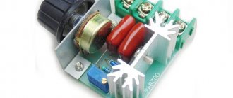
What is a 220 V voltage regulator
The abbreviated name of the device in question is RN 0–220 V. The simplest such device is a dimmer for incandescent lamps. The device adjusts the network voltage parameters, increases/decreases the degree of the output signal in a range depending on the value of the potential difference at its output. Maintains the specified voltage of the consumer circuit.
The device regulates (smoothly or stepwise) precisely the voltage value itself, the voltage, on which the power in the range of capabilities of the connected unit also depends. It works with reactive and active loads, you just need to check whether a particular assembly is suitable, especially for the latter. And also you always need to compare what power (Watts) the circuit is designed for.
The RN changes, according to user settings, the level of the output signal from the 220 V network supplied to the load connected to it. Thus, a parameter is set that is suitable for powering a particular device, and more often for adjusting its operation (reducing/increasing the speed of low-power electric motors, light brightness).
Important: RN-220 V lowers/increases only the voltage value (V) coming from the 220 V network - current (Amps), power (W, kW) it does not regulate, these values are changed by the payload itself, limited by the scope of its characteristics, according to the supplied volts. The device is sometimes called a “power regulator”, since the capabilities of the connected consumer according to the specified parameters also change. But the RN must be distinguished from that, as well as from the current regulator.
The voltage regulator is used:
- to change the speed of small motors of household devices (the speed of a blender, hair dryer), less often, since not all circuits are suitable, for more powerful motors (for example, a drill);
- for other devices whose operation can be customized. And more often (and this is the most correct and effective use) for the light level (dimmer), sound volume, heating of heating elements, soldering iron,
- in all cases, if it is necessary to create a certain voltage on the circuit, for example, 12 V.
It will be interesting➡ Connection diagram for a single-phase and three-phase electric meter: step-by-step instructions
Most often, household pH 0–220 V is used for smooth on/off. devices.
Factory models usually also have a microcircuit for stabilizing voltage during voltage surges, ensuring the operation of devices in any mode. According to English standards, a thyristor regulator is called Voltage Controller. RNs are supplied with universal power supplies on which the voltage can be adjusted.
Types, principle of operation, features
The RN on our topic is intended only for alternating voltage, that is, for a regular 220 V home network.
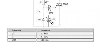
Most often they are assembled based on the following parts:
- thyristors;
- triacs;
- transistors.
The circuits also contain capacitors, constant and tuning resistors. It is the selectors of the latter that carry out the adjustment. Complex assemblies may include microchips.
RNs are most effective for resistive (reactive, ohmic) loads, that is, those that are part of the power consumption of the connected/disconnected consumer. This is resistance to the flow of current, such as a resistor, at the point where electricity is converted into heat.
Resistive loads are heating elements, heating elements, incandescent lamps (not “housekeepers”).
In an inductive load, the current (where it is much lower than with a resistive load) lags behind the voltage, and reactive power is created. These are asynchronous electric motors, electromagnets, chokes, transformers, rectifiers. The launch vehicles will not work with them, or they will, but not effectively, creating a risk of equipment failure. There voltage regulators are not always appropriate.
The thyristor device cannot be used with LED (economical) and fluorescent lamps. Capacitor regulators do not allow smooth voltage changes.
Disadvantages of thyristor memory
The simple circuit has a significant disadvantage - the lack of electronic protection against polarity reversal, short circuit and overload. This function is partially performed by a fuse, which is not very convenient. If desired and have sufficient experience, you can assemble an additional protection circuit and connect it separately.
The second drawback is the galvanic connection of the tuning unit with the network. This can be eliminated by using an adjustment resistor with a plastic shaft.
And another disadvantage is the need to install cooling radiators (it is better to use ribbed aluminum products). The problem is partially solved by using a circuit with the inclusion of a control module in winding I of the supply transformer.
To summarize, let’s say that assembling a thyristor charger with your own hands is not as difficult as it might seem at first glance. Perseverance and the time spent will be rewarded with an inexpensive, high-quality charger with smoothly adjustable current, extending the life of the battery.
Pulse power supply coils
Output transformer Tr1 is used from an old power supply. The transformation ratio is in the range from 3:2 to 4:3, and its core is ferrite, without a gap. If someone wants to wind it themselves, use a core similar to an inverter welder or about 6.4 cm2 (allowable range 6-8 cm2). The primary winding should consist of 20 turns, wound with 20 wires with a diameter of 0.5 mm, and the secondary winding should consist of 14 turns with 28 wires of the same diameter. Copper strips can also be used. Unfortunately, using one thick wire is not possible due to the skin effect.
Useful: 100 watt transistor sound amplifier - proven circuit
The control transformer Tr2 has three windings of 16 turns each. They are wound simultaneously (in three directions) with three twisted insulated wires. The core is EI (maybe EE) without clearance, taken from an ATX power supply. This core has a cross-section of the central part of approximately 80..120 mm2.
Current transformer Tr3 consists of 1 coil and 68 turns on a toroidal core. In general, the size and number of revolutions are not critical. But for another coefficient, the value of R15 must be adjusted.
The auxiliary power supply transformer Tr4 was wound on a ferrite core EE with a gap and a base cross-sectional diameter of about 16-25 mm2. It is taken from the inverter auxiliary transformer of the above ATX power supply. The direction of switching on the windings of all transformers (marked with dots) must be correct.
An inductor removed from a microwave oven can be used as a line filter choke. The output choke L1, like the transformer, is also from a ready-made UPS. It consists of two parallel 54 µH powder core chokes, and the resulting inductance is 27 µH. Each inductor is wound with two 1.7 mm wires.
L1 is on the negative side so that the diode cathodes can be attached to the heatsink without insulation. The maximum current of the power supply is about 2500 W, and the efficiency at full load exceeds 90%.
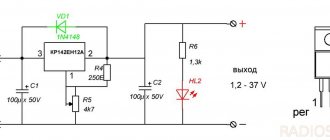
DIY thyristor voltage regulator
This cannot be said that this circuit will not provide galvanic isolation from the power source, so there is a certain danger of electric shock. This will mean that you do not need to touch the regulator elements with your hands.
You should design the structure of your device in such a way that, if possible, you can hide it in an adjustable device, and also find more free space inside the case. If the adjustable device is located at a stationary level, then it makes some sense to connect it through a switch with a special light brightness control. Such a solution can partially protect a person from electric shock, and will also relieve him of the need to find a suitable housing for the device, has an attractive external structure, and is also created using industrial technologies.