Today we’ll delve a little deeper into the theory and talk about rectifier circuits. Let's consider the principle of rectifying alternating current, the most common rectifier circuits, and the semiconductor elements that are used in these circuits.
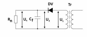
Rectifiers are devices designed to convert alternating current into direct current. The general circuit of a standard single-phase rectifier consists of a transformer, a rectifier unit based on semiconductor diodes and a smoothing filter in the form of a capacitor.
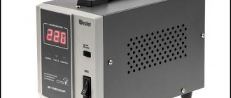
The transformer is used to convert 220 V AC network voltage into the required output load voltage. The rectifier unit (diode bridge) converts alternating current into direct pulsating current, and the smoothing filter converts it into a current close in shape to direct current.
Both four separate diodes and a diode assembly in a single housing can be used as diode rectifiers. In diagrams, a diode bridge is usually depicted as follows:
Modern rectifiers are distinguished by the type of rectifiers used, their connection diagram and the number of phases. Also, rectifiers can be controlled or uncontrolled.
Single-phase rectifiers
The main circuits of single-phase rectifiers are half-wave and full-wave (bridge or midpoint).
The single-phase half-wave circuit is the simplest rectifier circuit.
The transformer converts the mains voltage of the primary winding Uc into the voltage of the secondary winding U2 . Since diode D has one-way conductivity, current I2 will flow only with a positive half-wave of the secondary voltage; with a negative half-wave, the diode will be closed. Since the current in the load Rн flows only in one half-cycle, hence the name of the rectifier - half-wave.
The disadvantages of half-wave rectifiers include unipolar current, which, passing through the secondary winding, magnetizes the transformer core, changing its characteristics and reducing efficiency, high ripple levels and high reverse voltage on the diode.
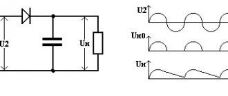
Full-wave rectification circuits are already much more interesting. Of these, the bridge circuit for connecting diodes has gained the most popularity.
The circuit consists of a transformer and four diodes assembled in a bridge. One of the diagonals of the bridge is connected to the terminals of the secondary winding of the transformer, the second diagonal is connected to the load. With a positive potential at point a of the secondary winding of the transformer, the current will flow through the circuit point a of the secondary winding - A - diode D1 - B - load Rн - D - diode D3 . this case, reverse voltage is applied to diodes D2 and D4 When the direction of the E.M.F and the current in the secondary winding changes, a positive potential will appear at point b of the secondary winding of the transformer. The current will flow through the circuit b - C - diode D2 - B - load Rн - D - diode D4 .
Thus, the current in the load does not change its direction. The voltage and current curves on the load repeat (at forward voltage on the diodes U np ≈ 0) in magnitude and shape the rectified half-waves of voltage and current of the secondary winding of the transformer. They pulsate from zero to maximum value.
In addition to the bridge rectification circuit, a bidirectional circuit can be used.
The circuit consists of a transformer with a middle tap on the secondary winding and two diodes. When there is a positive potential at point a , current flows through circuit a - diode D1 - load Rн - tap 0 of the secondary winding. With a positive potential at point b of the secondary winding, current will flow through circuit b - diode D2 - c - load Rн - tap 0 of the secondary winding.
The left figure shows the dependence of the voltage of the secondary winding of the transformer on time, the right shows the change in load current. As follows from the operation of the rectifier, the direction of the current in the load is unchanged. The secondary winding of the transformer is two-phase and each phase operates for half a period. The voltage across the load at any moment is equal to the instantaneous value of the EMF of the phase operating at the moment.
The main disadvantages of this circuit include the need to tap off the secondary winding of the transformer and the high reverse voltage of the diode Urev = 2U2m = 3.14U0, so it is not as widespread as a bridge circuit.
Operating principle
The operating principle of a three-phase rectifier
The operating principle of any sinusoidal voltage converter is based on the rectifying properties of a special semiconductor element - a germanium or silicon diode. When alternating current flows through it, the positive half-wave freely “passes” through the working electronic junction, biased in the forward direction. When exposed to a negative half-wave, the electrons encounter an obstacle in the form of a potential barrier, so that current cannot flow through the junction.
In the simplest switching circuits, an incomplete cycle of processing variable levels is used, since the second half-wave is irretrievably lost. This significantly reduces the converted power. To preserve the useful component, 2-half-wave rectification circuits were developed, in which the number of diodes was increased to two.
A “full cycle circuit” may contain 4 rectifier elements, but such a circuit belongs to the bridge category.
Three-phase rectifiers
Among three-phase circuits, the most widely used are the unidirectional rectification circuit or Mitkevich circuit and the bridge circuit, also known as the Larionov circuit.
Let us first consider a unidirectional rectifier circuit.
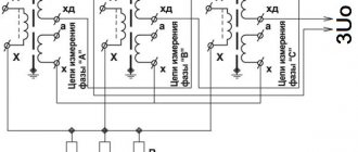
In a unidirectional circuit, the secondary windings of a three-phase transformer are connected in a star. Diodes D1 , D2 and D3 are to phases a , b and , the cathodes of which are connected at point 0 . The load Rн is connected between the common terminal of the three secondary windings of the transformer and the common point of connection of the cathodes.
Current will flow through each diode only when the potential at the anode is higher than the potential at the cathode. This is possible during 1/3 of the period when the voltage in a given phase is higher than the voltages in the other two phases. That is, when U2a>U2b and U2a>U2c , diode D1 will be open, while D2 and D3 will be locked. Under the influence of voltage U2a, the current is closed through the winding of phase a , diode D1 and load Rн . In the next third of the period, diode D2 , then D3 , etc.
The load voltage will be equal to the phase voltage with the diode open and therefore the load current changes according to the same law. In this case, the current in the load will always be greater than 0.
The current ripple in such a circuit will be relatively small, which reduces the requirements for the anti-aliasing filter. The disadvantage of this circuit, as well as the single-phase half-wave circuit, is the magnetization of the transformer core.
The Larionov bridge circuit has become more widespread in three-phase rectifiers, since it does not have the disadvantages of a single-cycle circuit.
In such a circuit, two diodes simultaneously pass current - one with the highest positive anode potential relative to the zero point of the transformer from the cathode group of diodes, the other with the highest negative cathode potential. The load is connected between the anode and cathode groups of diodes.
In the time interval t1-t2, D1 and D4 will pass current , since the anode of phase a , and the cathode of phase b . In the interval t2-t3 D1-D6 will pass current , in the interval t3-t4 - D3-D6 , in the interval t4-t5 - D3-D2 , in the interval t5-t6 - D5-D2 and in the last interval - D5-D4 .
Thus, the voltage across the load will have the form of six ripples per period, and the conduction interval of each diode will be 2π/3. In this case, the interval of joint operation of two diodes is π/6. The average voltage across the load will be:
where U2 is the effective voltage value on the secondary windings of the transformer.
The average value of the rectified voltage is almost equal to the maximum linear voltage of the supply network:
where Uab.m is the maximum linear voltage of the secondary winding.
One of the advantages of the circuit should be noted that in such a circuit there is no forced magnetization of the transformer core. In addition, the ripple coefficient is significantly lower than that of a single-phase full-wave circuit and amounts to 0.057.
Based on this circuit, you can create twelve, eighteen, twenty-four-phase rectifiers. For this, various combinations of serial and parallel circuit connections are used. The more phases and, accordingly, pairs of diodes there are, the less output ripple will be.
In addition to these circuits, controlled rectification circuits can also be used, which, along with rectifying the alternating current, also provide regulation of the output voltage (current). But we'll talk about this next time.
Application area
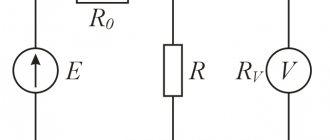
The results of a comparison of the advantages and disadvantages of the Vienna rectifier with other network converters with active power factor correction are presented in
.
The lower voltage on the switches of the Vienna rectifier allows the use of MOS transistors and operation with a high switching frequency, while the ratings of the inductors are reduced, the weight and dimensions are improved, and the control system is simplified. However, as the converter power increases, the capacitances of the filter capacitors and their costs increase. Therefore, the scope of application of Vienna rectifiers is limited to a load power of about 1-5 kW.
Literature
- Zinoviev G.S. Fundamentals of power electronics: textbook. Ed. 3rd. Novosibirsk: NSTU Publishing House, 2004.
- Ovchinnikov D. A., Kostrov M. Yu., Lukin A. V., Malyshkov G. M. Three-phase rectifier with power factor correction // Practical power electronics. 2002. Issue. 6.
- Chaplygin E. E., Nguyen Hoang An. Spectral modeling of power factor correctors // Practical power electronics. 2004. Issue. 15.
- Chaplygin E. E. Asymmetrical modes of a three-phase converter with power factor correction // Electricity. 2005. No. 9.
Checking elements
Often in homemade devices it is necessary to use parts that have already been used. All such components must be inspected before installation. Since the rectifier assembly consists of four diodes connected back-to-back in series, and the terminals of all diodes can be reached with a probe, the question of how to ring a diode bridge can be solved simply.
To do this, it is enough to measure the resistance of each diode with a regular ohmmeter, focusing on the rectifier circuit and the bridge pinout. In one polarity of the probes, the device should show high resistance, in the other - low. When the corresponding diode is broken, the resistance will be low in both positions of the probes; if it is burned out, it will be high.
Bridge device type
A three-phase bridge rectification circuit uses six diodes (or thyristors if control is required). The output voltage is characterized by three values: minimum U, average U and peak voltage.
A full-wave three-phase rectifier is similar to a Heitz bridge.
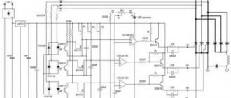
Diagram of a full-wave three-phase device. A conventional three-phase rectifier does not use a neutral . For 230 V / 400 V network between two rectifier inputs. Indeed, there is always a composite voltage U (= 400 V) between the 2 inputs.
An uncontrolled device means that the average output U cannot be adjusted for that input U. Uncontrolled rectification uses diodes.
A controlled rectifier allows you to regulate the average output voltage by influencing the response delay of the thyristor (used instead of diodes). This command requires complex electronic circuitry. The diode behaves like a thyristor loaded without delay. The rectified voltage looks like this.
Output U three-phase output voltage. There are 7 curves in total: 6 sinusoids and a red curve connecting the upper part of the sinusoids (“sinusoidal caps”). 6 sinusoids represent 3 voltages that make up U between phases and 3 identical voltages, but with opposite sign:
U31 = -U13U23 = -U32U21 = -U12.
The red curve represents U at the output of the rectifier, that is, at the terminals of the resistive load. This U does not refer to neutral. She swims. This U fluctuates between 1.5 Vmax and 1.732 Vmax (root of 3).
Umax is the peak value of one voltage and is 230 × 1.414 = 325 V.
see also
- half wave rectifier,
- full wave bridge rectifier, bridge rectifier,
- full-wave bridge rectifier with filter,
- semiconductor diode, current-voltage characteristics of diodes, classification of diodes, diodes,
Do you think that if three-phase rectifiers are improved, it will be better for us? I hope that now you understand what three-phase rectifiers are, a three-phase rectifier and what all this is needed for, and if you don’t understand, or if you have any comments, then don’t hesitate to write or ask in the comments, I will be happy to answer. In order to gain a deeper understanding, I strongly recommend that you study all the information from the category Electronics, Microelectronics, Component Base
Selection of rectifier diodes
When purchasing a device, you must be guided by the following parameters:
- values of the current-voltage characteristic of the maximum reverse and peak current;
- maximum permissible reverse and forward voltage;
- average rectified current strength;
- device material and type of installation.
It is also worth paying attention to the fact that rectifier circuits differ in the number of phases:
- Single-phase. Widely used for household electrical appliances. There are diodes for automobiles and for electric arc welding.
- Multiphase. Indispensable for industrial equipment, public and special transport.
Schottky diode
A special position is occupied by the Schottky diode. It was invented in connection with the growing needs in the developing radio electronics industry. Its main difference from other diodes is that its design includes a metal-semiconductor as an alternative to a pn junction. Accordingly, the Schottky diode has its own unique properties that silicon rectifier diodes cannot boast of. Some of them:
- operational renewability of the charge due to its low value;
- minimum voltage drop across the junction when connected directly;
- The leakage current is significant.
When making a Schottky diode, materials such as silicon and gallium arsenide are used, but germanium is also sometimes used. The properties of the materials are slightly different, but in any case, the maximum permissible reverse voltage for a Schottky rectifier is no more than 1200 V.
In contrast to all the advantages, the design of this type also has disadvantages. For example, in a bridge assembly, the device categorically does not perceive excess reverse current. Violation of the condition leads to breakdown of the rectifier. Also, a small voltage drop occurs at a low voltage of about 60-70 V. If the value exceeds this indicator, then the device turns into an ordinary rectifier.
Zener diode
To stabilize the voltage, a special device is used that can operate in breakdown mode - a zener diode, the foreign name of which is “Zener diode”. The device performs its function by operating in breakdown mode at a reverse bias voltage. The current increases at the moment of breakdown; at the same time, the differential value drops to a minimum, as a result of which the voltage is stable and covers a fairly serious range of reverse currents.
Full cycle circuit
It is a rectifier circuit that converts AC voltage to DC voltage. These circuits are called full-wave rectifier because it generates a full-cycle output signal.
Advantages of three-phase rectifiers:
- Due to their low cost compared to center push, they are widely used in the power supply circuit.
- This can be used to detect the amplitude of a modulated radio signal.
- Bridge rectifiers can be used to supply polarized voltage in welding.