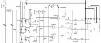
\main\r.l. designs\ power supplies\…
AC voltage rectifiers.
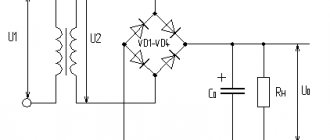
Rectifiers are used in power supplies for electronic devices to convert alternating voltage to direct voltage. The circuit of any rectifier contains 3 main elements:
- Power transformer is a device for lowering or increasing the voltage of the supply network and galvanic isolation of the network from the equipment.
- A rectifier element (valve) with one-way conductivity - to convert alternating voltage into pulsating voltage.
- Filter – to smooth out pulsating voltage.
Rectifiers can be classified according to a number of characteristics:
- according to the rectification circuit - half-wave, full-wave, bridge, with voltage doubling (multiplying), multiphase, etc.
- By type of rectifier element - tube (kenotron), semiconductor, gastronic, etc.
- By the magnitude of the rectified voltage - low voltage and high.
- Intended purpose: for powering anode circuits, shielding grid circuits, control grid circuits, collector circuits of transistors, for charging batteries, etc.
Main characteristics of rectifiers:
The main characteristics of rectifiers are:
- Rated DC voltage is the average value of the rectified voltage specified by the technical requirements. Usually the voltage before the filter U0 and the voltage after the filter (or its individual units - U) are indicated. It is determined by the voltage value required for the devices powered by the rectifier.
- Rated rectified current I0 – the average value of the rectified current, i.e. its constant component, specified by technical requirements. It is determined by the resulting current of all circuits fed by the rectifier.
- Mains voltage Umains is the voltage of the alternating current mains supplying the rectifier. The standard value of this voltage for a household network is 220 volts with permissible deviations of no more than 10%.
- Ripple is an alternating component of voltage or current at the output of the rectifier. This is a quality indicator of the rectifier.
- Ripple frequency is the frequency of the most pronounced harmonic component of the voltage or current at the output of the rectifier. For the simplest half-wave rectifier circuit, the ripple frequency is equal to the frequency of the supply network. Full-wave, bridge, and voltage-doubling circuits produce ripples whose frequency is equal to twice the mains frequency. Multiphase rectification circuits have a ripple frequency that depends on the rectifier circuit and the number of phases.
- Ripple coefficient is the ratio of the amplitude of the most pronounced harmonic component of the voltage or current at the output of the rectifier to the average value of the voltage or current. A distinction is made between the ripple factor at the filter input (p0%) and the ripple factor at the filter output (p%). The permissible values of the ripple coefficient at the filter output are determined by the nature of the load.
- Filtering coefficient (smoothing coefficient) – the ratio of the ripple coefficient at the filter input to the ripple coefficient at the filter output k c = p0 / p. For multi-link filters, the filtration coefficient is equal to the product of the filtration coefficients of individual links.
- Voltage fluctuations (instability) at the rectifier output – a change in DC voltage relative to the rated one. In the absence of voltage stabilizers, they are determined by network voltage deviations.
Rectifier circuits.
Rectifiers used for single-phase household networks are made according to 4 main circuits: half-wave, full-wave with a zero point (or simply full-wave), full-wave bridge (or simply bridge, less commonly called a “Graetz circuit”), and a voltage doubling (multiplying) circuit (Latour's scheme). For multiphase industrial networks, two types of circuits are used: Half-wave polyphase and Larionov circuit.
Three-phase rectifier circuits are most often used.
The main indicators characterizing rectifier circuits can be divided into 3 groups:
- Relating to the entire rectifier as a whole: U0 is the DC voltage before the filter, I0 is the average value of the rectified current, p0 is the ripple factor at the filter input.
- Determining the choice of a rectifying element (valve): Urev - reverse voltage (voltage on the rectifying element (valve) in the non-conducting part of the period), Imax - maximum current passing through the rectifying element (valve) in the conducting part of the period.
- Determining the choice of transformer: U2 is the effective value of the voltage on the secondary winding of the transformer, I2 is the effective value of the current in the secondary winding of the transformer, Ptr is the calculated power of the transformer.
Main characteristics of various rectification circuits.
A comparison of rectification circuits and an approximate calculation of the rectifier can be made using the data from the table.
| Circuit type | Uarr | I max | I 2 | U 2 | C0* | P0% | U C0 |
| Half-wave | 3 U0 | 7 I 0 | 2 I 0 | 0.75U0 | 60 I 0/U0 | 600 I0¯¯¯¯¯¯U0 *C0 | 1.2U0 |
| Full wave | 3 U0 | 3.5 I 0 | I 0 | 0.75U0 | 30 I 0/U0 | 300 I0¯¯¯¯¯¯ U0 *C0 | 1.2U0 |
| Pavement | 1.5 U0 | 3.5 I 0 | 1.41 I 0 | 0.75U0 | 30 I 0/U0 | 300 I0¯¯¯¯¯¯ U0 *C0 | 1.2U0 |
| Voltage doubling | 1.5 U0 | 7 I 0 | 2.8 I 0 | 0.38U0 | 125 I 0/U0 | 1250 I0¯¯¯¯¯¯ U0 *C0 | 0.6U0 |
* Capacitor value calculated for P0% = 10%
By setting the value of the voltage at the output of the rectifier U0 and the value of the rated current in the load (average value of the rectified current) I 0, you can easily determine the voltage of the secondary winding of the transformer, the current in the secondary winding, the maximum permissible current of the valves, the reverse voltage on the valves, as well as the operating voltage filter capacitor. Having specified the required ripple coefficient, you can calculate the capacitance value at the output of the rectifier.
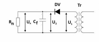
Half-wave rectifier.
The schematic diagram and voltage oscillograms at various points of the rectifier are shown in the figure.
U2 - Voltage on the secondary winding of the transformer
Un – Load voltage.
Un0 – Voltage across the load in the absence of a capacitor.
As can be seen in the oscillograms, the voltage from the secondary winding of the transformer passes through the valve to the load only during positive half-cycles of the alternating voltage. During negative half-cycles, the valve is closed and voltage is supplied to the load only from the capacitor charged in the previous half-cycle. In the absence of a capacitor, the ripple of the rectified voltage is quite significant.
The disadvantages of this rectification circuit are: High level of ripple of the rectified voltage, low efficiency, much greater than in other circuits, the weight of the transformer and the irrational use of copper and steel in the transformer.
This rectifier circuit is used extremely rarely and only in cases where the rectifier is used to power circuits with low current consumption.
Full-wave rectifier with zero point.
The schematic diagram and voltage oscillograms at various points of the rectifier are shown in the figure.
U2 - Voltage on one half of the secondary winding of the transformer
Un – Load voltage.
Un0 – Voltage across the load in the absence of a capacitor.
This rectifier uses two valves having a common load and two identical secondary windings of the transformer (or one with a midpoint).
In practice, the circuit consists of two half-wave rectifiers, having two different sources and a common load. In one half-cycle of alternating voltage, the current flows into the load from one half of the secondary winding through one valve, in the other half-cycle - from the other half of the winding, through another valve.
Advantage: This rectifier circuit has half the ripple compared to a half-wave rectifier circuit. The capacitance of the capacitor, with the same ripple coefficient as the half-wave circuit, can be 2 times less.
Disadvantages: More complex design of the transformer and irrational use of copper and steel in the transformer.
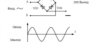
Bridge rectifier circuit.
The schematic diagram and voltage oscillograms at various points of the rectifier are shown in the figure
U2 - Voltage of the secondary winding of the transformer
Un – Load voltage.
Un0 – Voltage across the load in the absence of a capacitor.
The main feature of this circuit is the use of one transformer winding to rectify both half-cycles of alternating voltage.
When rectifying the positive half-cycle of an alternating voltage, the current passes through the following circuit: Upper terminal of the secondary winding - valve V2 - upper terminal of the load - load - lower terminal of the load - valve V3 - lower terminal of the secondary winding - winding.
When rectifying the negative half-cycle of an alternating voltage, the current passes through the following circuit: Lower terminal of the secondary winding - valve V4 - upper terminal of the load - load - lower terminal of the load - valve V1 - upper terminal of the secondary winding - winding.
As we can see, in both cases the direction of the current through the load (in italics) is the same.
Advantages: Compared to a half-wave circuit, a bridge circuit has a 2-fold lower ripple level, higher efficiency, more rational use of the transformer and a reduction in its design power. Compared to the full-wave circuit, the bridge circuit has a simpler transformer design with the same ripple level. The reverse voltage of the valves can be significantly lower than in the first two circuits.
Disadvantages: Increase in the number of valves and the need to bypass the valves to equalize the reverse voltage on each of them.
This rectifier circuit is most often used in a wide variety of devices. Based on this circuit, if there is a middle terminal from the secondary winding of the transformer, two more options for rectification circuits can be obtained:
In the left diagram, a tap from the middle of the secondary winding allows you to get another voltage, 2 times less than the main one. Thus, the main voltage is obtained from a bridge rectification circuit, and the additional voltage is obtained from a full-wave rectification circuit.
In the right circuit, a bipolar voltage is obtained with an amplitude 2 times less than that obtained in the main circuit. Both voltages are obtained using full-wave rectification circuits.
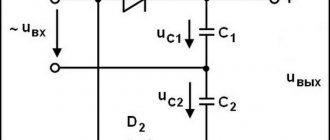
Voltage doubling circuit.
The schematic diagram and voltage oscillograms at various points of the rectifier are shown in the figure.
U2 - Voltage of the secondary winding of the transformer
Un – Load voltage.
A distinctive feature of this circuit is that in one half-cycle of alternating voltage one capacitor is “charged” from the secondary winding of the transformer, and in the second half-cycle another is charged from the same winding. Since the capacitors are connected in series, the resulting voltage across both capacitors (at the load) is twice as high as what can be obtained from the same secondary winding in a circuit with a half-wave rectifier.
Advantages: The secondary winding of the transformer can be designed for significantly lower voltage.
Disadvantages: Significant currents through the rectifier valves, The level of ripple is much higher than in full-wave rectifier circuits.
The same scheme can be used in two more options:
The left circuit is designed to obtain two supply voltages of the same polarity, the right circuit is designed to obtain a bipolar voltage with a common point.
In the second version of the circuit, the characteristics of the rectifier correspond to the characteristics of a half-wave rectifier.
Multiphase rectifiers.
Multiphase rectifiers are usually used only in industrial and special equipment.
Typically, industrial equipment uses three-phase rectifiers of two types - a three-phase rectifier and a Larionov rectifier.
Three-phase rectifier.
The schematic diagram and voltage oscillograms at various points of the rectifier are shown in the figure.
FA, FS, PV – voltages on the secondary windings of a three-phase transformer.
U va Uvb Uvc voltage at the load received from the corresponding valve.
Un – Total voltage across the load.
The rectifier is a half wave rectifier for each of the three phase secondary windings. All three valves have a common load.
If we consider the oscillograms of the voltage across the load with the capacitor disconnected for each of the three phases, we can see that the voltage across the load has the same level of ripple as in the half-wave rectification circuit. The phase shift (i.e., time shift) of the voltages of the rectifiers among themselves will result in a 3 times lower level of ripple than in a single-phase half-wave rectification circuit.
Advantages: Low level of rectified voltage ripple.
Disadvantages: As in the single-phase half-wave rectification circuit, low efficiency, irrational use of the transformer. This rectifier is not applicable to a conventional single-phase network.
Larionov's scheme.
The schematic diagram and voltage oscillograms at various points of the rectifier are shown in the figure.
This rectifier is a bridge rectifier for each pair of three-phase windings operating on a common load. Combining the advantages of a bridge rectifier and three-phase power supply, it has such a low ripple level that it allows operation with almost no smoothing capacitor or with a small capacitance.
Disadvantages: Increased number of valves. The rectifier also cannot be used for operation in a single-phase household network.
Rectifiers for transformerless power supply of equipment.
Transformerless rectifiers are the simplest non-autonomous direct current sources. They are used at voltages close to the mains voltage or exceeding it by 1.5 - 2.5 times and currents up to several tens of milliamps.
The limited use of transformerless rectifiers is explained primarily by safety requirements, since both poles of the rectified voltage are galvanically connected to the network. The second disadvantage of such rectifiers is the lack of flexibility when choosing the rectified voltage. For radio equipment, rectifiers can be used as transformerless rectifiers: Half-wave, bridge, voltage doubling. The main characteristics are the same as in the case of transformer power supply. The mains voltage is connected to the connection points of the secondary windings of the transformers (instead of the transformer).
Transformerless circuits are dangerous to use!
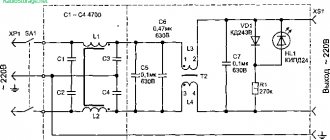
To power small-sized portable equipment with currents up to 15-20 milliamps, you can use half-wave or bridge circuits with quenching capacitors.
In this circuit, the capacitor Cgas plays the role of a “watt-free” reactance, forming a kind of voltage divider with the active resistance of the load.
The reactance of the quenching capacitor is given in the formula.
This circuit can be used for charging small-sized batteries of radios, radio stations and radiotelephones.
Care must also be taken when constructing and operating the rectifier!
Some recommendations for working with rectifiers.
The secondary windings of transformers must always be protected with fuses. In this case, a short circuit in the load circuit will not lead to such consequences as failure of the transformer, and even more so will not lead to a fire in the equipment.
Often when designing rectifiers, it turns out that there are no necessary valves (diodes) or capacitors with the required characteristics. In this case, you can use a parallel or series connection of valves or capacitors.
What do you need to remember?
If the available valves (diodes) have a permissible current less than the calculated maximum current, you can use a parallel connection of such diodes, multiplying their permissible current by the number of diodes in the “bundle”.
If the permissible reverse voltage of the valves (diodes) is less than the calculated value, you can use their series connection by connecting shunt resistors in parallel with each diode, which will equalize the reverse voltage between the diodes. The shunt resistance value is calculated using the formula:
Rsh = 700 * Urev / N for diodes with Urev less than 200 V and Imax = 1 - 10 Amperes
Or
Rsh = 150 * Urev / N for diodes with Urev more than 200 V and Imax less than 0.3 Ampere
If the capacitance of the capacitor is less than the design value, you can use parallel connection of several capacitors having an operating voltage not less than the design voltage.
If the operating voltage of the capacitors is less than permissible for a particular circuit, you can use series connection of capacitors, not forgetting that the total capacitance in this case will decrease as many times as the number of capacitors will be included in the series circuit.
Such a circuit can only be used as a last resort, since in such a circuit a breakdown (short circuit) of one capacitor will cause a “chain reaction”, since a greater voltage will be applied to the remaining capacitors in operation than was before the short circuit of one of them. Shunting capacitors with resistors in this case does not save the equipment from sequential failure of capacitors in the entire chain. It is better to use a series connection of several rectifiers designed for lower voltage. Then, if one of the capacitors breaks down, the output voltage will simply decrease.
This article provides only brief information on rectifier circuits. You can read more about the calculation of rectifiers in a variety of literature.
The following literature was used in preparing the article:
V.Ya. Bruskin “Nomograms for radio amateurs” MRB 1972.
B. Bogdanovich, E. Vakser “Brief radio engineering reference book” Belarus 1968.
All the best!
73! N. Filenko (UA9XBI)
| Voice of the people |
| 02/25/2015 01:28 thank you! but I’ve known this for a long time since 1967... - 11/10/2014 11:57 diagram... - 10/11/2013 19:01 DOUBLEING THE TENSION ACCORDING TO THE TRONFOMATOR SCHEME... - ayub 09/02/2013 11:58 Thank you, I’m new to electronics and this one the article clarified a lot for me... - Slavik 03/10/2013 18:53 THANK YOU, GOOD ARTICLE. PARALLEL AND SERIES DIAGRAMS... - Gennady 02/14/2013 09:40 If I decided to engage in education, I would withstand the alphabet... - VAK 12/26/2012 02:02 In a three-phase network, the shift between any phases is 120 degrees. And... - ABC 02/08/2012 06:27 I assembled a charger for car batteries thanks to... - 02/08/2012 06:27 I assembled a charger for car batteries thanks to... - 11/22/2011 15:40 Author 5+well done my friend!!! I've been looking for similar diagrams for a long time. Pomnits... - turbine 10/11/2011 00:50 Wonderful article) really only a guide. Thanks... - Nonamerz 10/11/2011 00:50 Wonderful article) really only a guide. thanks... - Nonamerz 06/09/2011 20:05 tell me where to find the circuit diagram of the airfield rectifier VA-2x750-... - topor 05/07/2011 16:28 Hello, I have a current question: is it possible to use a UBP 400 rectifier with... - Alexander K... 04/13/2011 09:05 Good, suitable, kosher article. Thank you!... - Vasily 03/01/2011 11:21 Aftar - kill yourself up the wall! Variable is current and not voltage... - Tranced, first... 12/16/2010 20:19 Thank you. They didn’t even help, but saved... — Sanya Dyak 12/16/2010 20:19 Thank you. They didn’t even help, but saved... - Sanya Dyak 06/29/2010 20:51 I need a schematic diagram of a full-wave AC rectifier with two... - 06/12/2010 15:20 BAD... - VASYA 02/20/2010 10:05 I need a circuit diagram of VDM 1202... - tnv50 01/13/2010 16:27 Cool article... - Ira 07/07/2009 20:31 Thank you very much for the information. If possible, the circuit can be straightened... - Andrey 05/26/2009 23:40 Hello, dear N. Filenko! I have a question about yes... - Evgeny 04/16/2009 19:26 Input to the voltage rectifier (2-phase AC) 220... - Natalia 07/02/2008 22:14 Actually, I don’t see the calculation itself... - Yunnat 05/26/2008 16:47 Dear N. Filenko (UA9XBI), in the section “Larionov Rectifier” V... - 02/11/2008 16:33 In the section “Three-phase rectifiers” the “three-phase” rectifiers are not described... - Andrey 12/10/2007 23:20 Little information about voltage doubling circuits... — Miss 17.11.2007 17:22 The computer power supply uses a pulse generator. R... - Pro 08.11.2007 01:04 Thanks, dude.... - Comrade 07/21/2007 22:46 it’s just clear and for whom this is useless, look for benefits in another m... - 05/06/2007 21:25 I have a question: how can I make it easier to switch the load from... - Rognier 01/31/2007 20:30 button accordion... ... - “Master of Pyupe... 12/17/2006 05:48 Awesome, great for insta, the author is incredibly grateful... - Vovka 10/30/2006 17:34 Drinking yadu)))) son........ - Devils Dance... 04/01/2006 17 :22 I DON’T KNOW, I HAVEN’T READ... - I 03/31/2006 08:20 A useless article that carries virtually no useful information... - Bill Gates 09/29/2005 11:18 Indeed, the publication is useful. However, in the section on doublers... - Vladimir 03/24. 2005 15:23 I have a question. I have a rectifier from an old computer. At 200 in... - ZiRO 08.26.2004 19:08 Excellent article, everything is simple and clear!!! :)… — Sashko |
Features of the operation of rectifiers, or how to correctly calculate the power of a power transformer.
To correctly calculate a transformer, you need quite complex calculations, radio amateurs use simplified formulas and amateur radio programs for these purposes, which, in principle, also allow this to be done quite accurately, so I will also try not to deviate from this tradition and will try to explain everything using practical examples and ready-made calculations using a minimum of formulas and calculations.
As usual, the power transformer is calculated. Knowing the voltage and current that the secondary (or several secondary) windings (U2 and I2) should provide, we find the power of the secondary circuit: If there are several secondary windings, the power is calculated by adding the powers of the individual windings. The power of the secondary winding P2 according to Ohm’s Law is equal to;
From here you can find the power of the primary winding, where for medium-power transformers we take the transformer efficiency of 0.9 (90%) to our calculations. For transformers of lower power, the efficiency is correspondingly lower (0.8). The power of the primary winding P1 (transformer power) in this case will be equal to;
That is, let me explain, if the calculated power of the secondary winding(s) is, for example, 100 W, then the total power of the transformer will be equal to 111.1 W (100/0.9). This does not yet take into account the no-load current, which is also added to the total power of the transformer.
How to check ripple
What is power factor
Measuring pulsation at home without a pulse meter and lux meter is a very problematic task. Approximately how much the light source blinks is not so difficult. As a rule, this harmful effect is invisible to the naked eye. However, if you use a mobile phone camera, the pulsations become noticeable. The assessment is carried out using characteristic horizontal stripes on the smartphone screen.
Stripes on a smartphone camera
Operation of the rectifier for an active load.
Half-wave rectifier.
Let's place a rectifier diode in front of the load. That is, we have a half-wave rectifier.
For measurement safety, this entire structure was connected via an isolation transformer. Variable wire resistances of various values with a power of 25 W were used as load resistors. The effective load current was set to 0.5 amperes (figure above). The measurement limit is 100 mV, the shunt in the secondary circuit is 0.1 Ohm. The resistance of the variable resistor was 19 Ohms, the effective voltage at the load was 9.5 volts. That is, the power consumed by the load turned out to be 4.75 W. Let's measure the current consumed by the primary winding.
The primary winding current turned out to be 97 mA, minus 7 mA XX, for a total of 90 mA. The voltage on the primary winding is 215 volts. The power consumed by the primary winding turned out to be 19.35 W, that is, 4 (four) times more than the power of the consumed load. Why is that? For those who are interested in all the details of the processes taking place in a transformer, I recommend reading the primary sources given at the end of the article; for those who are too lazy to read, I will try to explain it in a simple way.
For example, already with a load current of 1.0 Ampere, the load voltage was 9.0 Volts, the load resistance was 9.0 Ohms, the load power was 9.0 W. The primary winding current turned out to be 230 mA (minus 7 mA) for a total of 223 and the voltage on the primary winding was 210 volts. The total power consumption of the transformer is 46.83 W, that is, 5.2 times more than the power consumed by the load. The idle current increased greatly with increasing load current (which increased the magnetization of the core).
Full-wave rectifier.
Let's see how he behaves. Let's assemble a full-wave rectifier circuit. This circuit requires a transformer tapped from the midpoint of the secondary winding. The transformer is different, the secondary winding has a voltage of 193-193 Volts, its current is 36 mA (as I found it). Using wire resistors I set the load current to 150 mA.
The load resistor turned out to have a resistance of 1.17 kOhm, the measured voltage across it was 175 Volts. The power consumed by the load turned out to be 26.17 W. Let's look at the current of the primary winding.
The primary winding current is 210 mA, minus the XX current (36) for a total of 174 mA. The power consumed by the transformer was 38.28 W. This is 1.46 times more power consumed by the load. As you can see, the performance here is much better than that of a half-wave rectifier. Go ahead.
Bridge rectifier circuit.
Let's check how the bridge rectifier circuit behaves. To do this, we will assemble the following diagram.
Let’s take the transformer that was there before, with one secondary winding from the first case under consideration for a half-wave rectifier. I set the load current to 0.5 A, the variable wire resistance turned out to be 32 Ohms. Load voltage 16 Volts. The power consumed by the load turned out to be 8 W.
We look at the current consumed by the primary winding.
Primary current 53 mA minus XX current (7 mA) = 45 mA. The power consumed by the primary winding was 9.9 W. This is 1.23 times more than the power consumed by the load. As you can see, the performance here is even better than that of a full-wave rectifier, not to mention a half-wave rectifier.
Algorithm for calculating ripples
The pulsation coefficient is calculated using specialized software and tables. The main stages of the process are as follows:
- building a computer model of the lighting system, taking into account the area of the room, ceiling height and reflective ability of the walls;
- grouping of light sources by individual power phases (L1, L2, L3);
- calculation of the minimum number of grid squares N1 for a square room;
- distribution of lamps across grid squares;
- measurement of lighting at control points (for each individual phase);
- determination from the table of parameters Kpoy and Kpi, depending on the type of light bulbs used;
- calculation of the overall pulsation coefficient of the lighting system Kpob, numerically equal to the arithmetic mean of its values at individual points.
Overall ripple factor
Calculation of room index
Its future light parameters depend on the index of the room. The calculation is performed as follows.
Room index
Here a and b are the length and width of the room, h is the distance from the working surface to the lighting fixtures. From the equality it is obvious that the index of the room is proportional to its area. The work surface is defined as a plane at a height of 800 mm from the floor (a typical desk).
Calculation of the smallest number of grid squares N
The calculation is relevant for premises of any shape. The geometric characteristics of the room are taken into account, such as its area (Sp). The parameter N is proportional to the number of squares N1.
Number of grid squares N
Here Sк is the area of the square formed by the smallest wall of the room.
Calculation of the luminaire pulsation coefficient Kpi
This calculation is necessary in order to take into account the ripple of the luminaires connected to one of the phases (Kpis). The type of light bulbs is also taken into account.
Lamp pulsations
Negative impact of non-compliance
Insufficient levels of illumination and its pulsations have a detrimental effect on human health. Violations of the rules can cause chronic diseases. The everyday factors of poor light include excessive eye fatigue, headaches, depression and absent-mindedness.
Pulse frequency perception threshold
The frequency at which the flickering light begins to appear continuous depends on the individual characteristics of the individual. For most people it is between 30 and 60 Hz. There are also differences in how exactly to look at an object. The eyes are most susceptible to pulsations when it comes to peripheral vision. When looking directly, sensitivity decreases.
Stroboscopic effect
The stroboscopic effect is, for the most part, characteristic of industrial enterprises and workshops with machine tools and other dangerous equipment. Fluctuations in light combined with sluggish vision can create unwanted illusions. For example, if the rotation speed of a lathe is a multiple of the lighting pulsation, then a person looking at the rotating part will see that it is stationary. This effect is fraught with injury and is characteristic of all moving units.
A rotating part appears to be stationary
Ripple coefficients of various light sources
Different lighting fixtures differ in the degree of pulsation. Outdated incandescent light bulbs are the best in this regard. Their tungsten spiral practically does not have time to change in brightness at the moments when the mains voltage passes through zero. In addition, the old light bulb pulsates at twice the network frequency, i.e. at 100 Hz. This parameter exceeds the sensitivity of most people.
Fluorescent and LED lamps, especially outdated ones, are less good. It all depends on the quality of their electronics. Sometimes there are samples on sale whose blinking is noticeable to the naked eye. More expensive models do not have this defect.
Attention! The use of dimmers significantly increases ripple. This is especially felt at low brightness of the light bulb. Also, dimmers (especially triacs) introduce unwanted interference into the network.
How to remove pulsation in an LED lamp
The easiest way is to buy a new light bulb from a quality manufacturer. If you need to tidy up the lighting device you have at hand, then the first step is to increase the capacitance of the input and output electrolytic capacitors. The larger they are, the lower the ripple coefficient. If it doesn’t help, then the problem lies either in the LEDs themselves or in their driver (chip). With such a diagnosis, it is easier to return to the first method and replace the light bulb with another one.
Capacitors in a LED light bulb
Additional Information. Capacitors at the output of the diode bridge are needed to rectify and smooth out the mains voltage. When replacing them, do not exceed the rated voltage, otherwise they will most likely explode.
From the above, it can be emphasized that calculating the pulsations of light sources is an important and responsible job. Without carrying out all the necessary calculations, it is impossible to design industrial, public or domestic buildings.
Definition and formula of ripple factor
Voltage ripple coefficient (Kp) is a value that determines the ratio of the maximum component of the alternating voltage (Uac.max.) to its constant component (Uconst). For convenience, it is expressed as a percentage.
Calculation of voltage ripple factor
Current ripples are calculated in the same way.
Calculation of current ripple factor
Iper. Max. is the alternating component of the current. Iconst. is its constant component.