This article will discuss typical connection diagrams for current transformer (CT) windings and relays.
In three-phase AC electrical networks of all voltage classes, CTs for powering relay protection devices are installed in two or three phases: as a rule, in 6 and 10 kV networks with low ground fault currents in two phases (A and C), in 35 kV networks and necessarily in networks of 110 kV and above in three phases. All three phases are equipped with CTs in networks with voltages up to 1 kV, if they operate with a solidly grounded neutral.
When performing current protection, the following four schemes for connecting the secondary windings of the CT and the current circuits of the current relay are used [L1, p. 41]:
- full star (three-phase, three-relay);
- partial star (two-phase, two-relay);
- partial star with a relay in the return wire (two-phase, three-relay);
- switching on a relay for the current difference between two phases (two-phase, single-relay).
Circuits are characterized by the ratio of the relay current lp to the secondary current I2 of the CT, called the circuit coefficient.
What is a current transformer
Current transformers are electrical devices that are used in high-current circuits to carry out safe current measurements, as well as to connect protective devices with low internal resistance.
Structurally, such devices are low-power transformers connected in series to the circuit of electrical equipment where medium and high voltage levels are present. Readings are taken in the secondary circuit of the device.
Standards for current transformers standardize the following technical parameters of devices:
- Transformation coefficient.
- Phase shift.
- Strength of insulating material.
- The magnitude of the load capacity in the secondary.
- Terminal markings.
The main rule that you need to remember when assembling a connection diagram for the windings of a current transformer is the inadmissibility of idling in the secondary circuit. Based on this, you can select the following operating modes for the CT:
- Load resistance connection.
- Operation during short circuit (short circuit).
What is a voltage transformer
A separate group of transformers used in alternating current networks with voltages over 380 V. The main task of the devices is to supply power to measuring instruments (IP), relay protection circuits and galvanic isolation of equipment from high-voltage lines for the safety of operating personnel.
The design of the VT is not fundamentally different from the TS. They lower the voltage to 100 V, which is already supplied to the power supply. Instrument scales are calibrated taking into account the transformation ratio of the measured voltage on the primary winding.
Diagram of the relay for the current difference of 2 phases.
In circuits with relays switched on for full phase currents, the currents in the relay Ip generally differ from the secondary phase currents I2ph of the measuring transducers. This difference is characterized by the circuit coefficient: kcx =Iр/I2ф, which may depend on the operating mode of the protected element. If the current I2ph is expressed through the primary current I1ph and the transformation ratio KI of the measuring transducer, then kcx = Iр *KI / I1ph.
This relationship is also valid for the relay operation current Iс.р and the protection operation current Iс.з, i.e. kcx =Iс.р*KI/Iс.з. When determining trip currents, symmetrical mode is usually considered.
Circuit for the difference in currents between two phases.
The relay current is equal to the geometric difference between the currents of the two phases
Advantage: 1. Cost-effective. Only one relay is used.
Disadvantages: 1. Different sensitivity for different types of short circuit; 2. This circuit fails to operate in some types of two-phase short circuit.
MTZ. Execution options.
Overcurrent protection is a maximum current protection that reacts to an increase in current above a certain value. In networks up to 1 kV, MTZ is performed using fuses, electromagnetic and thermal circuit breakers. Above 1 kV, fuses (TP 10/0.4 and 35/10) and relay circuits are also used. The use of relay circuits makes the protection more reliable and sensitive. MTZ on relay circuits is performed using direct and indirect relays, using three or two-phase circuits, using direct or alternating current.
Technical versions can be:
— with RTV and RTM relays, secondary direct-acting relays built into the circuit breaker drive.
— using secondary indirect relays RT, EV, RP
MTZ Operating principle.
Overcurrent protection is a type of relay protection, the action of which is associated with an increase in current strength in the protected circuit when a short circuit occurs in a section of this circuit. This type of protection is used almost everywhere and is the most common in electrical networks.
The principle of operation of the MTZ is similar to the principle of operation of the current cut-off. If the current in the protected network increases, the protection begins to work. However, if the current cut-off acts instantly, then the maximum current protection gives a signal to turn off only after a certain period of time, called the time delay. The time delay depends on where the protected area is located. The shortest time delay is set at the area furthest from the source. The MTZ of the neighboring (closer to the energy source) section operates with a longer time delay, differing by an amount called the selectivity level. The selectivity level is determined by the duration of the protection. In case of short circuit in the area its protection is triggered. If for some reason the protection does not work, then after a certain time (equal to the selectivity level) after the onset of the short circuit, the overcurrent protection of the section closer to the source will operate and turn off both the damaged and its own section. For this reason, it is important that the selectivity stage is greater than the protection response time, otherwise the protection of the adjacent area will turn off both the damaged and the working area before the damaged area’s own protection has time to operate. However, it is also important to make the selectivity level small enough so that the protection can operate before the short circuit current causes serious damage to the electrical network.
The setting is selected based on the lowest value of the short circuit current in the protected area. However, when choosing a setting, you should also take into account the nature of the protected network. For example, when electric motors self-start after a power outage, the current in the network may be higher than the rated current, and the protection should not turn it off.
MTZ is implemented, as a rule, using a current relay. Current relays can be either instantaneous or triggered with a time delay determined by the current value; in this case, a time relay is additionally used to ensure the required time delay. In modern relay protection and automation schemes, microprocessor protection units are most often used, which combine the properties of these relays.
MTZ. Calculation of current setting
Maximum current protection (MCP) is a type of relay protection, the action of which is associated with an increase in current strength in the protected circuit when a short circuit occurs in a section of this circuit. This type of protection is used almost everywhere and is the most common in electrical networks.
The principle of operation of the MTZ is similar to the principle of operation of the current cut-off. If the current in the protected network increases, the protection begins to work. However, if the current cut-off acts instantly, then the maximum current protection gives a signal to turn off only after a certain period of time, called the time delay. The time delay depends on where the protected area is located. The shortest time delay is set at the area furthest from the source. The MTZ of the neighboring (closer to the energy source) section operates with a longer time delay, differing by an amount called the selectivity level. The selectivity level is determined by the duration of the protection. In the event of a short circuit in the area, its protection is triggered. If for some reason the protection does not work, then after a certain time (equal to the selectivity level) after the onset of the short circuit, the overcurrent protection of the section closer to the source will operate and turn off both the damaged and its own section. For this reason, it is important that the selectivity stage is greater than the protection response time, otherwise the protection of the adjacent area will turn off both the damaged and the working area before the damaged area’s own protection has time to operate. However, it is also important to make the selectivity level small enough so that the protection can operate before the short circuit current causes serious damage to the electrical network.
The setting (or the current value at which the protection is triggered) is selected based on the lowest value of the short circuit current in the protected network (short circuit currents differ for different faults). However, when choosing a setting, you should also take into account the nature of the protected network. For example, when electric motors self-start after a power outage, the current in the network may be higher than the rated current, and the protection should not turn it off.
In some cases, these protections provide higher selectivity through the use of additional blocking. For example, microprocessor protection can improve the detuning of powerful electric motors from inrush currents by changing the setting for the duration of the inrush current flow (start-surge mode). It is possible to change the overcurrent protection setting to quickly shut down the facility when the supply line is turned on for an unresolved previous short circuit.
The current relay setting for single-stage overcurrent protection is determined by the load current and is calculated by the formula:
where IC3 is the protection operation current, A;
InMAX — maximum load current, A;
kн—reliability coefficient;
kSZAP - self-start coefficient;
kB is the return coefficient.
The reliability coefficient is a calculated value determined by the expected inaccuracy of the relay settings, time and temperature deviation from the initial settings, and some other factors. For relays of type RT-40, RT-80, RT-90 it is in the range of 1.1-1.2.
The self-start coefficient is determined by the nature of the load, that is, the increased consumption of motor load when restoring power after a break.
The return coefficient is determined from the expression:
where IB is the relay return current;
ICP is the relay operating current.
The return coefficient is determined by the technical characteristics of the relay and is realized by the quality of its adjustment.
The protection operation current obtained from expression (4-1) should ensure the sensitivity of the protection during short circuits at the most remote point of the protected section of the network:
where Ik.min is the minimum short-circuit current at the end of the protected section of the network.
For basic protection, kch >1.5 is accepted. If this is not met, other circuit solutions can be adopted (for example, replacing overcurrent protection with distance protection). In some cases, the required sensitivity coefficient can be obtained by adjusting the return coefficient of the current relay within acceptable limits.
MTZ. Time delay calculation
When there is a short circuit, the current in the line increases. This feature is used to perform current protection. Overcurrent protection (MCP) comes into action when the current in the line phases increases above a certain value.
a time delay is used to ensure selectivity
, and
current cutoffs
, where selectivity is achieved by choosing the operating current. Thus, the main difference between different types of current protection is in the method of ensuring selectivity.
Protection time delay
To ensure selectivity of the time delay, the MTZs are selected in a stepwise manner. The difference between the protection time of two adjacent sections is called the time step (selectivity step): Dt=t2–t1.
The time step Dt should be such that during a short circuit on line w2, the MTZ II (Fig. 4.2.1) does not have time to operate.
Determination of selectivity level Dt:
During a short circuit at point K, protection I operates for the time: tзI=tввI+tпI+tвI, where tввI is the time delay of protection I; tпI – error in the direction of deceleration of protection time relay I; tвI – switch off time of switch Q1.
Condition for failure of protection II during a short circuit on line w2: tввII>tввI+tпI+tвI
The protection time delay II can be defined as: tввII=tввI+tпI+tвI+tпII+tзап, where tпII is the error in the direction of reducing the protection II time delay; tzap – reserve time. Thus, the minimum time step Dt can be calculated as: Dt=tввII – tввI=tпI+tвI+tпII+tzap.
The formula determines the time stage for protections with an independent response time characteristic of the current. It is recommended to take Dt =0.35…0.6 s. Selecting the duration of protection:
calculation starts from the overcurrent protection installed at electricity consumers tвв(n)= tвв(n–1)+ Dt
t1=0; t2=0.5s; t3=1s; t4=1.5s; t5=2s.
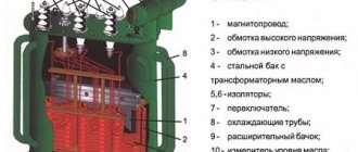
What is a power transformer
The main electrical machines used at substations and in everyday life are power transformers. They act as voltage converters from one value to another, while maintaining the shape of the electrical signal. There are step-down and step-up electric machines.
Vehicles can be three-phase or single-phase with two or three windings. Three-phase ones are usually used for energy redistribution in powerful electrical networks; single-phase ones can be found in any household equipment, for example, power supplies.
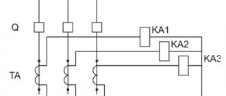
Connection diagrams for CT windings
There are the following basic circuits for connecting the secondary windings of a current transformer when powering protective relay devices:
- Full star diagram. In this case, current transformers are switched in all power phase lines. Their secondary windings are connected by a star circuit to the relay windings. All CT terminals of the same value must converge to the zero point. According to this scheme, its own relay will respond to a short circuit (short circuit) of any phase. If a short circuit occurs on the ground bus, then a relay will operate in the star (in the zero wire).
- Connection diagram of transformer windings in a partial star. This option involves installing CTs not on all phases, but only on two. The secondary windings are also connected to the relay with a star. This circuit is effective only when there is a short circuit between phases. In case of a phase short circuit to zero (where the CT was not installed), the protection system will not work.
- The triangle circuit is on transformers, the star is on relays. Here the CTs with their opposite terminals of the secondary windings are connected in series with a triangle. The vertices of this triangle go to the rays of the star, where the relay is installed. The circuit is used for such types of protection as distance and differential.
- CT connection diagram based on the two-phase difference principle. The circuit reacts only to phase-to-phase short circuits with the required sensitivity.
- Zero-sequence current filtering circuit.
Relay protection and automation project
Schemes with two current transformers per connection (partial star scheme) are one of the most common in 6-35 kV networks.
Previously, such schemes were used in projects by default at most connections, starting from the line and ending with 35/6 kV transformers. In reality, a partial star circuit usually has the same sensitivity as a full star circuit if you are using a three-relay relay protection system.
However, there is one type of damage in which this relay protection circuit can lead to very unpleasant consequences. We'll talk about this in today's article.
As you probably guessed, this type of damage is a double ground fault. Moreover, only one type of distribution of closure points leads to problems, namely the one shown in Fig. 1
Rice. 1. Option of double ground fault in 6-35 kV networks
The progression of the accident may look like this:
— First, a single-phase ground fault occurs on phase A (or C) in the higher network. OZZ is not an emergency mode and can exist in the network for quite a long time (during the search for “ground”);
— Despite the absence of short-circuit currents, the insulation of healthy phases, including phase B, are under the influence of linear voltages. Due to overvoltage, a breakdown of phase B insulation occurs in the downstream switchgear (for example, busbars or cutting of an outgoing cable);
— We get a double ground fault through phases A (or C) and B, and these points are at different distribution levels. The downstream input protection, made according to a two-transformer circuit, does not detect a double ground fault current, despite the fact that this is already an emergency current;
— Double circuit is disabled by higher-level protection.
I think the situation is clear. In practice, such cases, although relatively rare, do occur.
The first question is that there is a non-selective disconnection of the connection (if the input protection had worked, then the double circuit would again turn into an OZZ, which can be worked with). But that's not the worst thing.
Much worse is that the shutdown occurs with a time delay that should not exist. If the second short circuit was on the buses, then, for example, the LZSh will not work.
It’s even worse if the fault is arc-based – your arc protection simply won’t work (there’s a flash, but no current). The MTZ delay on the linear switch from above can be 1-1.5 seconds, during which the arc will destroy the cell, or even the entire section.
Thus, you should not use two-transformer circuits on the inputs and CBs. On lines and other connections this is not so critical because arc protection is usually not started from their overcurrent protection.
It is also worth analyzing the influence of this factor on checking the thermal resistance of the screens of single-core XLPE cables extending from such substations (with relay protection and protection according to the partial star circuit), in the event of a second short circuit on the cable.
The screens of such cables are checked specifically for a two-phase ground fault, and here it is necessary to correctly determine the shutdown time. Perhaps it will be much higher than the time of your own MTZ. But more about this some other time.
Connection diagrams for voltage transformer windings
Regarding VTs, when they power protection relays and measuring equipment, they use both phase-to-phase voltage and linear voltage (between phase and ground). The most commonly used schemes are based on the principle of open triangle and incomplete star.
A triangle is used when there is a need for two or three phase-to-phase voltages, a star when connecting three VTs, if phase and line voltages are used simultaneously for measurements and protection.
For electrical devices with two additional secondary windings, a connection circuit is used where the main windings of the primary and secondary purposes are connected by a star. Using an open triangle, additional windings are assembled. With such a circuit it is possible to obtain a 0-sequence voltage for the relay system to respond to a short circuit in a circuit with a grounded wire.
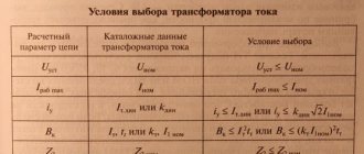
Current transformer connection diagrams. Scheme coefficient.
Purpose of TN. VT connection diagrams.
Information about the controlled voltage of the IO RZ is obtained from the primary voltage transformers (VT). The main parameters of the VT (Fig. 6.1) are: rated primary voltage U1nom (equal to the rated voltage of the controlled electrical network), secondary rated voltage U2HOM, the value of which is usually taken equal to 100 or 100/V. The ratio of these values, called the nominal transformation ratio, KUNom = U1nom / U2nom [24].
The beginnings and ends of the primary and secondary windings of VT H (n) and K (k)
are designated by manufacturers in the same way as for power transformers: for the primary winding with the letters
A and X, for
the secondary winding, a and
x, respectively.
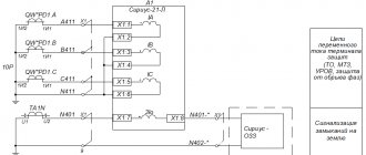
To power relay protection devices, in most cases, voltage transformers are used, installed on the busbars of substation and switchgear stations of power plants, to the secondary windings of which the relay protection of all connections is connected (Fig. 6.2, a), or at each connection, feeding the relay protection of only this connection.
The first method is more economical than the second, since it requires less voltage transformers, but its disadvantage is that if it is necessary to switch the connection from one bus system to another, it is necessary to switch the relay voltage circuits to the voltage transformers of another bus system. This switching is done automatically using QS auxiliary contacts,
disconnectors installed on the blades, as shown in
rice. 6.3, or repeater relays controlled by them. This operation can be performed manually using special switches.
The weak point of automatic switching is the auxiliary contacts, the failure of which leads to incorrect operation of relay protection devices. The disadvantage of the second method is that the error of the person conducting the switching cannot be excluded, but its advantage is the greater reliability of the circuits. When using VT connections, if the corresponding connection is transferred to another bus system, no operations in the voltage circuits are required.
The automatic method of switching voltage circuits is usually used in power plants and large substations with a large number of connections.
Timed cut-offs
Instantaneous cutoff protects only part of the power line; in order to perform protection protection of the entire power line with a minimum operating time, a cutoff with a time delay is used (see Fig. 5.2, b). The zone and time of action of such cutoff 1 (Fig. 5.7, o, b) are consistent with the zone and time of action of instantaneous cutoff 2 so that selectivity is ensured.
To meet these conditions, the operating time of the relay t31 of cut-off 1 is selected to a step t greater than t32 of cut-off 2:
t31 = t32 + t. (5.5)
Depending on the accuracy of the cut-off time relay 1t3 = 0.3 0.6 s. The operating area of cutoff 1 should be shorter than the operating area of cutoff 2 (Fig. 5.7, c).
In a network with one-way power supply, coordination of coverage areas of RP 1 and 2 is ensured if the condition is met
Ic..z1 = kotsIs.z2, (5.6) where kOTC = 1.1 1.2. The cut-off area 1 (AN in Fig. 5.7, a) is found graphically.
In a network with double-sided power supply, the currents IK1 and IK2 passing through cutoffs 1 and 2 are not the same (Fig. 5.8): IK2 > IK1. Taking this into account, coordination of the coverage areas of cutoffs 1 and 2 is usually performed graphically. For this purpose (Fig. 5.8), the dependence of IK1 and IK2 on the distance l to the short circuit point is plotted.
By the intersection of straight line Iс.з2 with curve IК2 (point M), the end of the cut-off zone 2 is determined. From point M, it is necessary to build cut-off 1. To do this, along the curve IК1 the current IК1М is found, passing in RE 1 during a short circuit at the end of cut-off zone 2 (point M).
In accordance with condition (5.2): Is.z1 = kotsIk1(M) . (5.6a)
The calculation is carried out at the maximum IK1 and minimum IK2 values. The current Ic.z must also be detuned from IkA during a short circuit on the buses of substation A. The cutoff area is determined by the intersection point of Ic.z1 and Ik1. Cut-off circuits with a time delay are performed in the same way as overcurrent circuits with an independent characteristic (4.2).
Current cut-offs are the simplest relay protection. The speed of action combined with the simplicity of the circuit is an important advantage of these relays. The disadvantages of cutoffs are: incomplete coverage of the protected power line and variability of the coverage area due to changes in the power system mode.
By combining MTZ 1 with instantaneous cut-off 3 and time-delayed cut-off 2, it is possible to obtain a three-stage MTZ that provides rapid shutdown of faults on the protected line W1 and redundant protection protection 4 and 5 of the next section. The characteristic time of operation of a three-stage MTZ is shown in Fig. 5.9.
Purpose of TN NAMI-10.
Voltage transformers (VT) are designed to lower high voltage to a value equal to 100 V, necessary to power measuring instruments, automation circuits, alarms and protective devices.
Three-winding transformers with an additional secondary winding are used to power protective devices.
The use of voltage transformers allows the use of standard measuring instruments for high voltage measurements, expanding the measurement limits; relay windings switched via VT can also have standard designs.
A voltage transformer isolates meters and relays from high voltage, making them safe to operate.
VTs are used in external or internal AC electrical installations with a voltage of 0.38 - 110 kV and a nominal frequency of 50 Hz. The accuracy of electrical measurements and electricity metering, as well as the reliability of relay protection and emergency automation, depend on their operation.
A VT with two secondary windings is intended not only to power measuring instruments and relays, but also to operate in a ground fault alarm device in a network with an isolated neutral.
Three-winding transformers of the NAMI series are designed for networks with an isolated neutral.
NAMI – anti-resonance oil voltage transformer with a winding for insulation control;
Voltage transformers of the NAMI series are designed to generate a measurement information signal for electrical devices, metering, protection and alarm circuits in networks with an isolated neutral or grounded through an arc suppression reactor. The transformer is resistant to short circuit currents and arc discharges on the line.
Purpose of TN NAMI-10.
Current transformer connection diagrams. Scheme coefficient.
A complete star. In normal mode and three-phase short circuit
phase currents
I
a =
I
A/
K
through relays
I, II
and
III ;
I
b =
I
B/
K
I;
I
c =
I
C/
K
I,a in the neutral wire – their geometric sum:
=0, which is equal to zero in symmetric modes. , 1,2,3 relays were triggered.
For two-phase short circuit
(AB) current flows only in two damaged phases and, accordingly, in the relays connected to the CT of the damaged phases, there is no current in the undamaged phase:
I
C = 0, Iop = Ia + Ib = 0. , 1.2 relays were activated.
Partial star. Current transformers are installed in two phases and connected in the same way as in a star connection. With 3-phase short circuit
.
Relays I
and
III
carry currents of the corresponding phases
I
a =
I
A/
K
I;
I
c =
I
C/
K
I, and in the return (common) wire (relay
IV)
the current is equal to their geometric sum:
Taking into account the vector diagram I
a
+ I
c
=
–I
b
,
i.e. I o.p is equal to the current of the phase absent in the secondary circuit
.
, 1.2,3 relays worked.
With AB and BC I
a =
I
A/
K
I,
I
c =0, , , 1.3 relays were activated.
With AC I
a =
I
A/
K
I;
I
c =
I
C/
K
I,
I
V=0, , 1.2 relays were activated.
Switching on the CT for the difference in secondary currents. Current transformers are installed in two phases; their secondary windings are connected by opposite terminals, to which the relay winding is connected. From the current distribution it is clear that the current in the relay I
p is equal to the geometric difference between the currents of two phases
I
a and
I
c
,
i.e.
where I
a =
I
A/
K
I;
I
c =
I
C/
K
I.
For three-phase short circuit
the current difference
I
a
– I
c is times greater than the current in the phase (
I a
and
I
c) and, therefore,
With a two-phase AC short circuit
:
With a two-phase short circuit AB or BC,
the relay receives current from only one phase
I
or
I
c
:
where I
f =
I
a or
I
f =
I
c.
Triangle. The secondary windings of the CT, connected in series with opposite terminals, form a triangle. From the current distribution it is clear that a current flows in each relay equal to the geometric difference between the currents of the two phases:
With a symmetrical load and a three-phase short circuit, a current passes through the relay that is times greater than the phase current and is shifted in phase by 30° relative to it:
Connection diagram of CT to NP current filter. KA relay winding is connected to them
.
The current in the relay is equal to the geometric sum of the secondary currents of the three phases: I
p =
I
a +
I
b +
I
c = 3
I
0.
The circuit under consideration is an NP current filter. Current in the relay appears only during single- and two-phase short circuits to ground. Therefore, the circuit is used for relay protection from short circuit to ground.
Turning on a relay according to this circuit is equivalent to connecting it to the neutral wire of a star.
21. List the basic requirements for relay protection elements. Damage protection must satisfy four basic requirements: to act selectively, quickly, to have the necessary sensitivity to damage and to perform its functions reliably. Selectivity , or selectivity, of a relay protection is its ability to disconnect only the damaged section of the network. So, during a short circuit at point K1
(Fig. 1.11) The relay protection must disconnect the damaged power line using switch
Q2
closest to the location of the damage.
With this action of the relay protection, the power supply to all consumers, except those powered by the damaged power line, is maintained. In the case of a short circuit at point K2,
with the selective action of the fault, the damaged power line
W1 should be disconnected,
and the power line
W2
should remain in operation.
At the same time, all consumers retain power. Selectivity of the relay protection is a mandatory requirement; deviation from it is allowed only to ensure speed of operation, when non-selective shutdown does not entail dangerous consequences. Speed of action . Switching off short circuits should be done as quickly as possible to limit the extent of destruction at the fault location, ensure thermal stability of equipment, cable and overhead power lines, increase the efficiency of automatic reclosure of power lines and busbars, reduce the impact of voltage reduction on the operation of consumers and maintain the stability of parallel operation of power plant generators. The permissible time for switching off a short circuit under the condition of maintaining stability depends on the duration and depth of the voltage reduction, characterized by the value of the residual voltage on the buses of the power plant and the node substation connecting the power plants with the electric power system. The lower the residual voltage, the more likely the instability is and, therefore, the faster the short circuit needs to be turned off. The given total time for disconnecting the short circuit tо.к
is the sum of the operating time of the relay protection
t3
and the switch
tВ
breaking the short-circuit current
tо.к=(t3+tВ)
.
Sensitivity. The relay protection must have sufficient sensitivity when a short circuit occurs within its coverage area. So, for example, P31
must turn off faults in the
AB
(first - main), protected by
P31,
and, in addition, have sufficient sensitivity to act in the event of a short circuit in the next (second - redundant) section
of the BC
, protected by
P32.
The last function of
P31
is called long-range redundancy.
Such redundancy is necessary to disconnect the short circuit in the event that the relay protection
of the second section (
P32
) or switch
Q2
does not operate due to a malfunction.
Thus, RP intended for long-distance backup must also be sensitive to short circuit at the end of the next section. Thus, the sensitivity of the relay protection must be sufficient for its reliable operation during a short circuit at the end of the zone established for it in the minimum mode of the power system and during short circuits through the transition resistance RP. Reliability
.
The reliability requirement is that the relay protection must operate without failure in the event of damage within the zone established for it and should not operate incorrectly when its operation is not intended.
Failure to operate or incorrect action of the relay leads to additional disruption of the power supply to consumers, and sometimes to accidents of system significance.
For example, in the event of a short circuit at point K1
and failure
of P31,
P33
will operate , resulting in additional shutdown of substations
II
and
III,
and if
P34
in normal mode, power line
W4
, and consumers of substations
I-IV
will lose power. The reliability of relay protection devices is ensured by the simplicity of their circuits, the reduction in the number of elements, relays, contact connections, the simplicity and reliability of the designs and circuits used, relays, semiconductor elements, the quality of manufacturing of auxiliary equipment and installation materials,
8. Types of damage, what causes lead to damage and abnormal operating conditions of electrical networks. Most faults in the EPS lead to short circuits (short circuits) of the phases between each other or to the ground. In the windings of electrical machines and transformers, short circuits can also occur between the turns of one phase. The main causes of damage are: 1) violations of the insulation of live parts caused by its aging, overvoltage, and mechanical damage; 2) damage to power line wires and supports caused by their unsatisfactory condition, ice, hurricane winds, “dancing of wires” and other reasons; 3) personnel errors during operations (turning off disconnectors under load or turning them on to an erroneously left grounding, etc.)
Abnormal modes include those associated with deviations from the permissible values of current, voltage and frequency that are dangerous for equipment or stable operation of the power system. Types: 1) Equipment overload caused by overcurrent, i.e. increase in current above the rated value; 2) Oscillations in systems occur when generators running in parallel are out of synchronism; 3) An increase in voltage above the permissible value can occur on hydrogenerators, as well as on high-power turbogenerators operating according to a block diagram, when they are suddenly disconnected from the network; 4) Asynchronous mode. Abnormal modes also include the operation of a synchronous generator without excitation [for example, when the automatic field suppression machine (AGF) is turned off]. When operating in asynchronous mode, the generator rotation speed increases and stator current ripple occurs.
Connection diagrams for power transformer windings
For three-phase networks, there are three main circuits for connecting the windings of power transformers. Each of the methods of such connection has its own influence on the operating mode of the transformer.
A star connection is when there is a common point of union of the beginnings or ends of all windings (zero point). The following pattern is present here:
- Phase and line currents have the same magnitude.
- The phase voltage (between phase and neutral) is less than the linear voltage (between phases) by the root of 3.
With regard to the windings of high voltage (HV), medium voltage (MV) and low voltage (LV) the following schemes are more often used:
- They connect the HV windings with a star, bringing the wire out from the zero point for increasing and decreasing T of any power.
- The MV windings are connected in the same way.
- LV windings are rarely connected with a star in step-down transformers, but when this happens, the neutral wire is brought out.
A delta connection involves connecting a transformer in series in a circuit where the beginning of one winding has contact with the end of another, the beginning of another with the end of the last, and the beginning of the last with the end of the first. Electricity outlets emerge from the vertices of the triangle. In this connection diagram of the windings of a three-phase transformer there is a pattern:
- Phase and line voltages have the same magnitude.
- Phase currents are less than linear currents by the root of 3.
As a rule, the LV windings of any step-down and step-up three-phase T are connected into a triangle into two or three windings, as well as powerful single-phase ones assembled in groups. For HV and MV, a delta connection is usually not used.
A zigzag-star connection is characterized by equalizing the magnetic flux across the phases of the transformer if the load on them in the secondary windings is unevenly distributed.
CT connection diagrams
“full star” CT connection diagram (Fig. 2.7) is usually used in networks with a grounded neutral with U³110 kV. In networks with an isolated neutral U £ 35 kV, such a scheme is rarely used - in critical electrical installations (for example, busbar protection). The coefficient of such a circuit is kСХ = 1 (the ratio of the current flowing through the relay to the current flowing through the secondary winding of the CT). In relay KA4, triple the zero-sequence current flows. This is not difficult to prove; according to the method of symmetrical components, the phase currents are equal:
. (2.11)
In relay KA4, the currents of phases A, B and C are added. As a result, the sums over the components of the direct and reverse sequences become equal to zero, since
, (2.12)
and the resulting current flowing through relay KA4 is 3IA0 . Usually in the index the designation of phase A is omitted and written 3I0 .
“partial star”
CT connection scheme is used exclusively in networks with an isolated neutral U £ 35 kV. For such a circuit kСХ = 1 , since the currents in the relay and in the secondary winding of the CT are equal. A feature of the circuit is that from two CTs it is possible to obtain the third phase current - IB , by connecting relay KA3 to the return wire:
I2A + I2C = - I2B , (2.13)
since for a symmetrical three-phase network the equality is satisfied (zero-sequence currents are neglected, because with single-phase ground faults they are disproportionately less than operating ones).
The CT connection diagram in a “triangle” (Fig. 2.9) is usually used in networks with U ³ 110 kV for differential protection of the transformer on the high voltage side. The coefficient of such a circuit can be calculated using Kirchhoff’s first law by finding the currents in the CT node of phase A:
, (2.14)
where we find the current in the relay:
. (2.15)
Considering that, according to the vector diagram (Fig. 2.10), it is easy to calculate:
(2.16)
The diagram (Fig. 2.11) for connecting a CT to a phase difference (previously this scheme was called “incomplete triangle” or “figure of eight” ) is used in networks with an isolated neutral with U £ 35 kV, most often to protect high-voltage electric motors, but sometimes also to protect lines, less often transformers. Similarly, as for the CT connection diagram in “ triangle ” , its. “ triangle ” diagram , so the expression (2.14) is obtained for the node.
Its advantage is the presence of one relay, simplicity. The disadvantage is the low sensitivity during turn short circuits of the motor winding in phase B.
zero sequence current filter circuit is shown in Fig. 2.12. Used in networks with a grounded neutral with U ³ 110 kV for zero-sequence current protection. Since this circuit is a filter, there is no concept of a circuit coefficient for it. 3I0 flows through the relay
-
can be proven similarly to the “full star” scheme.
series connection (Fig. 2.13) is used to increase the load capacity of the CT. For this purpose, CTs with the same kT . Since the current flowing through the CT is the same, and the voltage across the load is divided by two, the load on each CT is halved. Often this circuit is used on the high voltage side of a transformer with a Y/D connection circuit for its differential protection.
A parallel CT connection (Fig. 2.14) is used to reduce kT . If CTs have the same kT , then the resulting transformation ratio will be half as much.
Schemes and groups of connections of transformer windings
In addition to connection diagrams, there are groups that mean nothing more than a displacement of the vector directions of the linear EMF of the primary windings relative to the electromotive force in the secondary windings. These angular differences can vary within 360 degrees. Factors defining the group are:
- Direction of winding turns.
- Method of placement on the coil core.
For convenience, the designation of groups adopted an hourly angular reading, divided by 30 degrees. Therefore, there were 12 groups (from 0 to 11). With all basic connections of transformer windings, all displacements are possible at an angle that is a multiple of 30 degrees.
What is the third harmonic used for?
In electrical engineering there is the concept of magnetizing current. It is this that generates the electromotive force (EMF). The shape of such a current is not sinusoidal, since higher harmonic components are present here. The third harmonic is responsible for transmitting the phase voltage curve without distortion (a distorted shape is undesirable for the operation of the equipment).
To obtain the third harmonic, a prerequisite is a delta connection of at least one winding. If the connection diagram of the star-star transformer windings is taken as the basic one, for example, in transformers with two windings, it is impossible to obtain the third harmonic without additional technical intervention. Then a third winding is wound onto the transformer, which is connected in a triangle, sometimes without leads.