Electrical appliances can use direct or alternating voltage. They receive energy from a battery, battery or electrical network. In the latter case we are talking about alternating voltage. In order for an electrical appliance to be able to use it, it must have strictly defined characteristics. If you need to get direct current at the output, then a voltage rectifier is installed. To choose the right one, you need to know what types of rectifiers there are and how they work.
What is a rectifier
This device receives a sinusoidal signal at the input and converts it into a constant voltage of the required value. It is important to understand that the output result in most cases is not a smooth straight line. In fact, we are talking about a signal that is close to it. It is obtained as a result of pulse smoothing.
Typically, voltage rectification occurs in two stages. At the first, the incoming alternating current is converted so that it acquires the desired amplitude. Transformations are carried out using a transformer. At the second stage, voltage fluctuations are equalized.
The rectification process is based on the phenomenon of one-way conduction. In this case, current can pass in one direction, but not in the other. Previously, vacuum devices or synchronizing machines were used for this, but now such methods are not used. Semiconductor diodes are installed in modern rectifying devices.
Each such device consists of three blocks: a transformer, a rectifier and a smoothing circuit (filter). The first is designed to adjust the output voltage level. It uses alternating voltage at its input and output. The rectifier cuts off negative pulses and supplies only positive ones to the output.
Smoothing is usually done using a capacitor. When the voltage increases, a charge accumulates on its plates, and when it decreases, it is removed from them. Thus, sudden changes are smoothed out, making the output voltage acceptable for consuming equipment. The signal is not completely equalized, but it becomes suitable in its parameters for the electrical equipment used. The quality of the work performed is characterized by the rectification coefficient. Typically this is the ratio of the device's forward current to its reverse current. But such a calculation is acceptable for an ideal device. Thus, the rectification coefficient can reach several hundred thousand. The larger it is, the better the straightener does its job.
Rectifiers, which are based on semiconductor elements, are classified according to the following criteria:
- Output power (high, medium and low power).
- Power phase (single-phase, three-phase, polyphase).
- Type of valve control (controlled, uncontrolled).
- Type of load (active, active-inductive, active-capacitive).
The choice of device circuit depends on the load and the form of current consumption. In this case, it is necessary to take into account such parameters of rectifiers as:
- current;
- voltage;
- Power factor;
- output voltage ripple;
- efficiency.
Operating principles of rectifiers
The operation of rectifier devices is based on the property of one-way conductivity of elements. This can be done in different ways. Many industrial applications have become a thing of the past - for example, the use of mechanical synchronous machines or electric vacuum devices. Now valves are used that conduct current in one direction. Not long ago, mercury devices were used for high-power rectifiers. At the moment, they are practically replaced by semiconductor (silicon) elements.
What is a rectifier used for?
It is convenient to use alternating current for transmission and transportation of electricity. However, electrical appliances are often designed to use direct current. In order to convert alternating current into direct current, various rectification circuits are used. In particular, converting devices are needed for:
- formation of input voltage in high-voltage power plants. This is necessary, for example, for traction substations intended for electrolysis installations, powerful DC motors.
- automatic gain adjustment. The converting device allows you to obtain a constant signal, as well as information about the existing signal level and determines the required gain.
- smoothing out too sharp and sometimes random voltage fluctuations. This input current rectification is used for both household and industrial purposes. It ensures that even in the event of a malfunction in the supply network, the output current and voltage will be generated to ensure good and correct operation of the equipment.
The current rectifier is also used to detect modulated signals. Since more and more electricity is needed in everyday life and to solve production problems, substations are being modernized so that they operate more efficiently. Sometimes this leads to various distortions of the incoming AC voltage. In this case, it is beneficial for the consumer to independently install and use rectifiers, which are also called stabilizers.
Application of diodes
One should not think that diodes are used only as rectifiers and detectors. In addition, you can highlight many more of their professions. The current-voltage characteristics of diodes allow their use where nonlinear processing of analog signals is required. These are frequency converters, logarithmic amplifiers, detectors and other devices. Diodes in such devices are used either directly as a converter or form the characteristics of the device when included in the feedback circuit. Diodes are widely used in stabilized power supplies, as reference voltage sources (zener diodes), or as switching elements of storage inductors (pulse voltage stabilizers).
Rectifier diodes.
We recommend reading: DIY generator voltage regulator relay: diagram
Using diodes it is very easy to create signal limiters: two diodes connected back-to-back - in parallel serve as excellent protection for the input of an amplifier, for example, a microphone, from supplying an increased signal level. In addition to the listed devices, diodes are very often used in signal switches, as well as in logic devices. It is enough to recall the logical operations AND, OR and their combinations. One type of diode is LED. Once upon a time they were used only as indicators in various devices. Now they are everywhere, from the simplest flashlights to TVs with LED backlighting, it is simply impossible not to notice them.
Application benefits
The use of rectifiers by users is beneficial for the following reasons:
- The required basic parameters of the output voltage are set.
- The quality of the incoming power supply improves.
- A high efficiency of the equipment is ensured.
- Voltage ripple is reduced.
- The rectifier device can be used for a single-phase or three-phase network, depending on its structural diagram.
- The high efficiency of converting devices is combined with compactness and relatively low weight. Some models even provide remote control capabilities.
- The rectifier in most cases has negligible reactance.
Purpose and practical use
The scope of use of a bridge made of diodes is quite wide. These can be power supplies and control units. It is installed in all devices powered by a 220 volt industrial network. For example, TVs, receivers, chargers, dishwashers, LED lamps.
We recommend reading: Simple diagrams for beginner radio amateurs
Cars cannot do without it either. After starting the engine, the generator starts working, producing alternating current. Since the on-board network is all powered by constant voltage, a rectifier bridge is installed through which rectified voltage is supplied. The same constant signal also recharges the battery.
The rectifier device is used to operate the welding machine. True, it uses powerful devices that can withstand currents of more than 200 amperes. The use of diode assembly in devices provides a number of advantages compared to a simple diode. This straightening allows you to:
- increase the ripple frequency, which can then simply be smoothed out using an electrolytic capacitor;
- when working together with a transformer, get rid of the bias current, which makes it possible to more efficiently use the overall power of the converter;
- pass more power with less heat, thereby increasing efficiency.
But it is also worth noting the drawback due to which in some cases the bridge is not used. First of all, this is a double voltage drop, which is especially sensitive in low-voltage circuits. And also, when some of the diodes burn out, the device begins to operate in half-wave mode, which is why parasitic harmonics penetrate into the circuit, which can damage sensitive radioelements.
power unit
Not a single modern power supply can do without a rectifier. High-quality sources are manufactured using bridge rectifiers. The classic scheme consists of only three parts:
- A step-down transformer.
- Rectifier bridge.
- Filter.
A sinusoidal signal with an amplitude of 220 volts is supplied to the primary winding of the transformer. Due to the phenomenon of electromagnetic induction, an electromotive force is induced in its secondary winding and current begins to flow. Depending on the type of transformer, the voltage value is reduced by a certain value due to the transformation ratio.
An alternating signal with reduced amplitude appears between the terminals of the secondary winding. In accordance with the diode bridge connection diagram, this voltage is supplied to its input. Passing through the diode assembly, the alternating signal is converted into a pulsating one.
This form is often considered unacceptable, for example, for sound equipment or lighting sources. Therefore, a capacitor connected in parallel with the output of the rectifier is used for smoothing.
Three-phase rectifier
In production and in places where a three-phase network is used, a three-phase rectifier is used. It consists of six diodes, one pair for each phase. Using this type of device allows you to obtain a higher current value with low ripple. This, in turn, reduces the requirements for the output filter.
The most popular options for connecting three-phase rectifiers are the Mitkevich and Larionov circuits. In this case, not only six diodes can be used simultaneously, but also 12 or even 24. Three-phase bridges are used in diesel locomotives, electric vehicles, on drilling rigs, and in industrial gas and water purification plants.
Thus, the use of bridge rectifiers makes it possible to convert alternating current into direct current, which powers all electronic equipment. Making a diode bridge yourself is not difficult. At the same time, its use allows you to obtain not only a high-quality signal, but also increase the reliability of the device as a whole.
Diode device
When we talk about converting AC voltage to DC, it usually does not mean that the output will be expressed as a horizontal straight line. The quality of signal processing may vary depending on what type of device is used and how the device operates. It is only guaranteed that the output rectified voltage will have the same sign. The simplest conversion method is to use a circuit consisting of a diode and a load.
Types of diode rectifiers work as follows: alternating voltage is supplied to the terminals on the left. The diode allows only positive pulses to pass through. When negative ones arrive, the output appears zero. As a result, a voltage of the same sign is created. The graphs are presented below.
A rectifier with a diode is called simple, but is rarely used because it has obvious disadvantages. More than half of the energy is lost here, and the output voltage changes sharply, which is not acceptable for some electrical devices.
Half wave converter
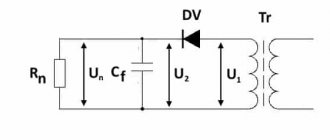
Below is a typical diagram of such a device with a minimum of elements.
Scheme: the simplest converter
Designations:
- Tr – transformer;
- DV valve (diode);
- Cf – capacitance (plays the role of a smoothing filter);
- Rn – connected load.
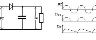
Now let's look at the oscillogram at control points U1, U2 and Un.
Oscillogram taken at control points U1, U2 and Un
Explanation:
- control point U1 displays a diagram taken at the device input;
- U2 – diagram in front of the capacitive smoothing filter;
- Un – oscillogram at the load.
The timing diagram clearly shows that after the valve (diode), the rectified voltage is represented in the form of characteristic pulses consisting of positive half-cycles. When such a pulse occurs, the charge of the capacitive filter accumulates, which is discharged during the negative half-cycle, this allows the pulsations to be somewhat smoothed out.
The disadvantages of such a scheme are obvious - it is low efficiency, due to the high level of ripple. But despite this, devices of this type find their use in circuits with low current consumption.
Half wave rectifier
The rectifier circuit with a capacitor is also considered one of the simplest. It looks like this:
As can be seen in the diagram, an alternating electric current rectifier with a capacitor is also equipped with a transformer that allows it to obtain the desired voltage. At this stage it remains variable, but changes amplitude. The rectifying action is based on the operation of a diode and a capacitor. Only the positive half-cycles of the sinusoid reach the capacitor plates, since the negative ones do not pass through the diode.
The top graph shows the sine wave of voltage entering the rectifier in the diagram shown. The lower one shows what this voltage will be as a result of passing through the diode.
The charge on the capacitor plates increases with increasing voltage. When it decreases to zero, it begins to drain, compensating for the jumps. The output receives a constant voltage. The circuit uses an electrolytic capacitor with a large capacity for this purpose. It is believed that the best converters for household equipment should have a capacity of at least 2200 microfarads.
How to organize bipolar power supply
By combining a balanced circuit and a bridge circuit, you can get a converter that will provide bipolar power at the output with a common (zero) point. Moreover, for one it will be negative, and for the other it will be positive. Such devices are widely used in power supplies for digital radio technology.
Diagram: example of a converter with bipolar output
Full wave rectifier
The rectifier in question is a rather complex device, the circuit of which includes a transformer with two secondary windings. Such a converter allows you to use not only positive half-cycles, but also negative ones.
A midpoint rectifier works as follows: the input voltage varies according to a sinusoidal law. During the positive half-cycle, the current will be rectified using the diode located in the upper part of the circuit (B1), and during the negative half-cycle, in the lower part (B2).
The bottom graph shows what voltage is generated after the diodes pass through. It will not accept negative values. Now it needs to be smoothed out. This is done using a powerful capacitor in a similar way to how it is implemented in a half-wave rectifier. A semiconductor full-wave rectifier provides a constant voltage with a smoothed signal at the output of the circuit.
Operating principle of a full-wave circuit
Let's consider two options for implementing a full-wave converter (rectifier): balanced and bridge. The diagram of the first is shown in the figure below.
The simplest uncontrolled balanced converter using two diodes using a transformer with a middle output
Elements used:
- Tr is a transformer that has two identical secondary windings (or one with a tap in the middle);
- DV1 and DV2 – valves (diodes);
- Cf – capacitive filter;
- Rn – load resistance.
For clarity, let us immediately present an oscillogram at control points.
Diagram of a balanced type device
- U1 – input oscillogram;
- U2 – graph in front of the capacitive filter;
- Un – diagram at the device output.
This circuit is two combined half-wave converters, that is, two separate sources account for one common load. The result of the operation of such a device is clearly demonstrated by graph U2. It shows that both half-cycles are used in the process, which gives these converters their name.
The oscillogram clearly demonstrates the advantages of such a device, namely the following facts:
- the ripple frequency at the device output doubles;
- reducing the “dips” between pulses allows the use of a smaller filter capacitance;
- A push-pull converter has greater efficiency than a half-wave converter.
Now let's look at the bridge type, it is shown in the figure below.
Diagram: Example of using a diode bridge
The oscillogram of a bridge type device is practically no different from a balanced one, so there is no point in presenting it. The main advantage of this scheme is that there is no need to use a more complex transformer.
Video: Full-wave rectifier bridge
Converters that use a semiconductor diode bridge are widely used both in electrical engineering (for example, in welding machines, where the rated current can reach up to 500 amperes) and in radio electronics, as a source for low-current circuits.
Note that in addition to semiconductor diodes, you can also use vacuum diodes - kenotrons (an example of a circuit diagram of such a device is shown below).
Scheme: converter based on a 6Ts4P two-anode kenotron
Actually, the presented circuit is a classic implementation of a full-wave balanced converter. Today, vacuum diodes are practically not used; they have been replaced by semiconductor analogues.
Bridge circuit
This popular electronic rectifier belongs to the full-wave category. The bridge circuit is one of the most common.
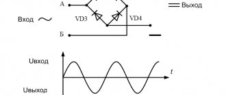
With alternating voltage, the direction of the current changes according to a sinusoidal law. This happens twice during one cycle. At a frequency of 50 Hertz, the direction changes 100 times per second. As a result of the operation of the diode bridge, only positive voltage pulses will be received at the output.
The diagram below shows how current flows through the diode bridge for each half-cycle. It chooses the appropriate route depending on the sign of the voltage.
When the top terminal is positive, current flows to the wire leading to the positive DC output, selecting the top right leg of the diode bridge. If the voltage is negative, then current flows from the bottom terminal to the indicated wire. The other branch of the circuit works in a similar way.
When assembling such a rectifier, the polarity of the bridge must be taken into account. Otherwise, you may connect the capacitor incorrectly, which may damage it. To do this, just remember the following rule. At the point where the cathodes are facing, you need to connect the positive wire, and at the point where the anodes are facing, you need to connect the negative wire.
The voltage will be supplied to the output from the diode bridge in the form of a sequence of pulses of positive polarity. When it increases, the capacitor charges, and when it decreases, it releases charge, smoothing out the pulses. As a result, a constant voltage is generated at the output of the circuit.
A converter consisting of a diode bridge can be made independently from four radio components or use a ready-made one. In the latter case, it is a solid element with markings on each output necessary for correct connection.
How to implement voltage doubling
Below is a circuit that allows you to obtain a voltage at the output of the device that is twice as high as the original one.
Voltage doubling circuit
It is typical for such a device that two capacitors are charged in different half-cycles, and since they are located in series, then, as a result, the total voltage at “Rn” will be twice as high as at the input.
In a converter with such a multiplier, transformers with a lower secondary winding voltage can be used.
Half-wave three-phase rectifier
Such electrical devices receive signals from each of the three phases and from zero. The diagram looks like this:
Additionally, a capacitor is used for smoothing. A similar method is used in a single-phase rectifier, but in a three-phase rectifier the smoothing is better due to the phase shift relative to each other.
Electronic rectifiers and stabilizers
Purpose, classification.
According to their functional tasks, semiconductor devices can be divided into three groups: converters, including rectifiers; amplification and pulse, including logic.
Conversion devices
convert the voltage and current of the energy source into the voltage and current required by the energy receiver.
Rectifier devices
are used to convert sinusoidal voltages and currents into direct ones.
The inverse conversion is implemented by inverters, and the change in the values of direct voltage and frequency of sinusoidal current is carried out by voltage and frequency converters. Converting devices are widely used in electric drives, electric welding devices, electrothermy, etc. In amplifying devices
, certain signal parameters are increased to the values necessary for the operation of actuators.
Using pulse and logic devices,
various control systems are created. The former provide the necessary time program, and the latter provide the necessary logical program for the joint operation of individual parts of the control object.
Note that the division of semiconductor devices according to their functional purpose is to a certain extent arbitrary. Real semiconductor devices often contain elements of several groups, as well as sine wave generators, voltage stabilizers, etc.
In the general case, the block diagram of a rectifier device (Fig. 1) contains a transformer T, a rectifier B, a smoothing filter F and a rectified voltage stabilizer St. The transformer serves to change the sinusoidal voltage of network C to the required level, which is then rectified. The smoothing filter reduces the ripple of the rectified voltage. The stabilizer maintains the voltage at the receiver P constant when the network voltage changes. Individual components of the rectifier device may be missing, depending on operating conditions.
Rice. 1
In the future, instead of the term “rectifier device” we will use the abbreviated term “rectifier”. According to the number of phases of the source of rectified sinusoidal voltage, single-phase and multiphase (usually three-phase) rectifiers are distinguished; according to the circuit design - with the output of the transformer zero point and bridge ones; according to the possibilities of regulating the rectified voltage - uncontrolled and controlled.
Uncontrolled rectifiers.
In uncontrolled rectifiers, diodes, i.e., uncontrolled valves, are turned on to rectify the sinusoidal voltage, and capacitive filters are usually used to smooth out the rectified voltage.
To simplify the calculations, we assume that the receiver is a resistive two-terminal network with a load resistance, and the diodes are ideal switches, i.e., they short-circuit the circuit for current in the forward direction and break it for current in the reverse direction.
Single-phase rectifiers: circuits, principle of operation, main parameters
In a single-phase rectifier with a zero terminal of the transformer
the receiver is connected to the terminal from the middle of the secondary winding of the transformer (Fig. 2). Let us first consider the operation of the rectifier without a smoothing filter (switch K is open). If in each half of the secondary winding with the number of turns w2 the direction of the current in which the corresponding diode is open is considered positive, then the current in each half of the winding and in each diode will be sinusoidal during the positive (for this half) half-cycle and equal to zero during the negative half period (Fig. 3 a). In the receiver, the positive directions of both currents coincide, i.e. (Fig. 3 b).
Rice. 2
With an ideal transformer, the constant component of the load current
and its actual meaning
equal to the values of the corresponding values of the sinusoidal current of the same amplitude.
Rice. 3
The current in the primary winding of a transformer with the number of turns w1 is sinusoidal
and is in phase with the sinusoidal network voltage (Fig. 3 c)
.
Let's consider how the operation of the rectifier will change after turning on the smoothing filter (switch K is closed). According to Kirchhoff's first law for node 1 of the circuit, the forward current of the diode VD1
or
Where
And
- voltage across the filter capacitor and current in it.
Substituting the current value i1 = 0 into this equation, we determine the moment of time t1 of the diode closing
where
Starting from time t1, the voltage at the receiver will change according to an exponential law:
,
as shown in fig. 4 a with a dashed line.
Rice. 4
At time t2, the voltage at the capacitor and at the rectifier input will be equal and the diode VD2 will open. Further, the process in the chain will be repeated periodically. The filter capacitor is periodically charged with current from the energy source and its subsequent discharge to the receiver circuit (Fig. 4 b).
Enabling the smoothing filter increases the DC component and reduces the percentage of harmonic components in the rectified voltage waveform.
Rice. 5
The dependence of the average value of the rectified voltage on the average value of the rectified current is called the external characteristic of the rectifier
. In Fig. Figure 5 shows the external characteristics of a single-phase rectifier without a smoothing filter (curve 1) and with a smoothing filter (curve 2). The decrease in voltage with a decrease in the resistance of the load circuit and an increase in the rectified current is explained by an increase in the voltage drop across a real diode with a nonlinear I-V characteristic, and in the second case, also by a faster discharge of the capacitor.
Rice. 6
Rice. 7
In a single-phase bridge circuit
rectification (Fig. 6), four diodes form four arms of the rectifier bridge. For one half of the period, two diodes in the opposite arms of the bridge conduct current, and the other two diodes are closed. The second half of the period, the other two diodes conduct current, and the first two diodes are locked (Fig. 7 a). For a bridge circuit, all the relationships obtained above for a rectifier with a transformer zero terminal are valid. The load current is rectified (Fig. 7 b), and the source current is sinusoidal (Fig. 7 a).
Three-phase rectifiers: circuits, operating principle, main parameters.
Multiphase rectification makes it possible to significantly reduce the ripple of the rectified voltage. In Fig. Figure 8 shows a diagram of a three-phase rectifier with a zero terminal of the transformer. At any given moment in time, current is conducted only by the diode whose anode is connected to the terminal of the secondary winding of a three-phase transformer (a, b or c), the voltage on which ( , , or ) is positive and greatest (Fig. 9 a).
Rice. 8
Rice. 9
For an ideal transformer, the currents of the secondary windings, and represent three sequences of pulses with a repetition period, duration and amplitude each, shifted relative to each other by 1/3 of the period (Fig. 9 b), the currents of the primary windings are equal
, ,
the load current has a constant component, and the rectified voltage coincides with the envelope of the positive half-waves of the voltages of the secondary windings (Fig. 9 c). Note that the currents in the secondary and primary windings of the transformer have constant components and , and the magnetic flux in its magnetic core is variable.
In a three-phase bridge circuit
a rectifier, the zero terminal of the secondary winding of a three-phase transformer is not needed, so its secondary windings can be connected either by a star or a triangle, or, if operating conditions allow, a three-phase transformer may be absent altogether. In the absence of a three-phase transformer, the rectifier is connected to a three-phase source, for example, as shown in Fig. 10. Half of the rectifier diodes (VD1, VD3 and VD5) form a group in which all cathode terminals are connected, and the second half of the diodes (VD2, VD4 and VD6) have all anode terminals connected.
Rice. 10
Let us take the value of the neutral point potential N of the three-phase source. In this case, the potentials of its terminals are respectively equal
;
;
,
as shown in Fig. 11 a. At any given moment of time, the diode of the first group is working, whose anode terminal has the greatest positive potential relative to the potential of the neutral point N. And along with it, the diode of the second group, whose cathode terminal has the greatest absolute value negative potential relative to the potential of the same point . To trace the order of switching of diodes, we divide one period T of the circuit into six equal time intervals, as shown in Fig. 11 a. In table 1 for each time interval shows the values with the highest positive potential of the anodes of the diodes of the first group and with the largest absolute value of the negative potential of the cathodes of the diodes of the second group, as well as the numbers of open diodes of each group. During one period, six switchings occur, i.e. 2 times the number of phases m=3.
Rice. eleven
Table 1
The operation of the rectifier is illustrated by time-aligned curves of the currents of the diodes of the first group i1, i3 and i5 (Fig. 11 b), the currents of the diodes of the second group i2, i4 and i6 (Fig. 11 c), load current and rectified voltage (Fig. 11 d) and alternating phase currents of a three-phase source, and (Fig. 11 d). Note that the maximum value of the rectified voltage is equal to the amplitude of the sinusoidal linear voltage of the three-phase source, and the maximum value of the rectified current is .
The power of multiphase uncontrolled rectifiers is usually medium or large (from tens to hundreds of kilowatts and more at currents up to 100,000 A). The power of single-phase uncontrolled rectifiers is low or medium (from units to tens of kilowatts). The efficiency of uncontrolled rectifiers reaches 98%.
Electrical filters.
In a circuit of periodic non-sinusoidal current, for various harmonic components of this current, the inductive reactances of the coils and the capacitive reactances of the capacitors depend on the number of the harmonic component.
of electrical filters is based on the dependence of inductive and capacitive reactances on frequency
- devices with the help of which the harmonic components of currents and voltages of a certain frequency or within a certain frequency band are significantly reduced.
Smoothing filters are devices designed to reduce rectified voltage ripple. Depending on the purpose of the electronic unit, the supply voltage ripple factor should not exceed certain values. For example, for amplification stages, Kp should not exceed 10-2 - 10-4%, and for self-oscillators - 10-3 - 10-4%.
The main elements of anti-aliasing filters are capacitors, inductors, resistors, and transistors. For direct current, the resistance of the capacitor tends to infinity, and the resistance of the inductor is very small and is determined by its active resistance. To quantify the effect of the filter, a filtration coefficient is introduced
,
where is the pulsation coefficient without a filter, and is the pulsation coefficient after the filter.
For example, for a capacitive filter.
Smoothing filters serve to reduce the percentage of harmonic components of the rectified voltage at the load resistance or reduce the percentage of higher harmonics in the alternating voltage curve.
The physical essence of the work of a capacitor and inductor (coil) in a filter is that a capacitor (usually of large capacity), connected in parallel with the load, is charged as the rectified voltage pulses increase and discharges as they decrease, thereby smoothing out its ripples. The choke, on the contrary, when the rectified current pulses increase as a result of the action of the self-induction emf, delays the current increase, and when the pulses decrease, it delays its decrease, smoothing out the current ripples in the load circuit. On the other hand, the capacitor and inductor can be considered as some kind of energy reservoirs. They store it when the current in the load circuit exceeds the average value, and release it when the current tends to decrease below the average value. This leads to smoothing of pulsations.
Let's consider the operation of the simplest smoothing filter (Fig. 12), which is a passive linear two-port network, to the output terminals of which a receiver with load resistance R2n is connected. The voltage transfer coefficient of the filter, the circuit of which, together with the receiver, is a circuit with a mixed connection of branches, is equal to
.
Rice. 12
Corresponding amplitude-frequency response of the filter
shown in Fig. 13.
Rice. 13
The higher the frequency of the harmonic voltage at the input and filter, the lower its percentage in the voltage at its output (Fig. 14).
Rice. 14
The angular frequency at which the amplitude of the sinusoidal voltage between terminals 2-2' is several times less than its value at an angular frequency equal to zero and a constant amplitude between terminals 1-1' is called the boundary angular frequency
, and the range of angular frequencies is
the passband
of the smoothing filter. Often, instead of angular frequencies, the corresponding cyclic frequencies are used.
A passive four-port network (Fig. 15 a) with its corresponding amplitude-frequency characteristics (Fig. 15 b) with an open load circuit ( ) also has the properties of a smoothing filter.
Rice. 15
The most common smoothing filters in rectifiers for electronic devices are U-shaped LC filters (Fig. 16 a). In them, the direct component of the rectified current, freely passing through the inductor Dr, then enters the load and is closed through the transformer. Variable components, being closed through large capacitors C1 and C2, do not pass into the load.
At small load currents, an L-shaped filter works successfully (Fig. 16 b), and at low load currents, it is enough to turn on a capacitor as a smoothing filter (Fig. 16 c), which is what is done in portable radios and radio tape recorders. In many cases, the inductor is replaced with a resistor, which somewhat reduces the quality of filtration, but significantly reduces the cost of the filter (Fig. 16 d, e). In the most critical cases, the anti-aliasing filter is made multi-section, consisting of several U-shaped or L-shaped LC or RC filters (Fig. 16 f).
Rice. 16
Resonant filters. Resonant filters use the phenomena of voltage and current resonances in electrical circuits to highlight or exclude a certain frequency band in the voltage waveform at the receiver. The corresponding filters are called bandpass filters
and
barrage
.
Rice. 17
In Fig. 17a shows a diagram of the simplest bandpass filter
based on the phenomenon of voltage resonance, and in Fig. 17 b - its amplitude-frequency characteristic, found by the formula:
.
The frequency bandwidth allocated by the filter is lower, the higher the quality factor of the circuit.
Rice. 18
In the barrier filter
according to the diagram in Fig. 18a uses the phenomenon of current resonance. Its amplitude-frequency characteristic
shown in Fig. 18 b. The bandwidth of frequencies blocked by the filter is determined at the level.
Combinations of voltage and current resonance phenomena in various filter branches make it possible to create high-quality bandpass and stop-band filters.
Selective RC filters. Filters containing only resistors and capacitors are called RC filters
.
The absence of inductive elements in them makes them attractive for implementation in the form of integrated circuits. An example of a bandpass RC filter is a four-port network (Fig. 19 a), called a Wien bridge
, with a voltage transfer coefficient when the load circuit is open
,
where and are complex resistances.
Rice. 19
The amplitude-frequency and phase-frequency characteristics of the Wien bridge are shown in Fig. 19 b. The maximum value of the amplitude-frequency characteristic is 1/3 and is achieved at the angular frequency
.
In this case, the phase-frequency characteristic crosses the abscissa axis, i.e. .
Rice. 20
A barrier RC filter can be implemented using a double T-shaped bridge (Fig. 20). When the load circuit is open, the minimum of its amplitude-frequency characteristic corresponds to the angular frequency.
Other circuit solutions for selective RC filters are also possible.
Thyristor rectifiers. Adjustment characteristic/
The principles of constructing controlled single-phase and multi-phase rectifiers are the same as the uncontrolled rectifiers of the same name, but diodes, i.e. uncontrolled valves, are replaced by thyristors, i.e. controlled valves. The program for turning on the latter is set by the corresponding sequence of control system voltage control pulses.
Let's consider the operation of a single-phase controlled rectifier with a transformer zero terminal
(Fig. 21). The operating mode of the rectifier generally depends on the values of the load circuit parameters. The most common are two cases. The load circuit equivalent circuit contains:
1) a resistive element with resistance;
2) series connection of resistive and inductive elements.
Rice. 21
To simplify the analysis, let us assume that a transformer with the number of turns of the primary and each half of the secondary windings is ideal with voltages on the halves of the secondary winding and (Fig. 22 a).
In the absence of load circuit inductance, the two arms of the rectifier operate independently of one another (Fig. 22 c) as single-phase, half-wave controlled rectifiers, the sequences of control voltage pulses coming from the control system control system (see Fig. 21) are shifted relative to each other by half period (Fig. 22 b). At the control angle, the current in the primary winding of the transformer is not sinusoidal (Fig. 22 d), and the current in the load circuit is a sequence of pulses with a duration and repetition period (Fig. 22 d).
The presence of inductance in the load circuit (Fig. 23) changes the nature of the process in the rectifier. After opening the thyristor VS1 or VS2, the current in it and in the load circuit smoothly increases and energy is stored in the magnetic field of the inductive element. Due to this energy, the current in the corresponding thyristor and in the load circuit will not decrease to zero when the polarity of the supply voltage changes. Consequently, the open state intervals of thyristors VS1 and VS2 will increase the more, the greater the inductance value. At a certain value of inductance, the current in the load circuit becomes continuous, and at a certain value it becomes constant. Switching of thyristors under the accepted assumptions occurs instantly.
Rice. 22
Rice. 23
Let us consider the operation of the rectifier in more detail, assuming that the inductance and at time t=0 the thyristor VS1 was closed and the thyristor VS2 was open. The first control pulse after time t=0 opens the thyristor VS1 and the voltage between its anode and cathode becomes zero ( ). At the value of the control angle (Fig. 24 a), the voltage between the anode and cathode of the previously conducting thyristor, as follows from Kirchhoff’s second law for circuit 1 of the circuit (Fig. 23), will have a negative value ( ), which leads to its blocking. At the same time, the positive voltage u1 > 0 (Fig. 24 a), acting in circuit 2 of the circuit, determines the current in the open thyristor VS1 and in the load circuit.
Rice. 24
After 1/2 of the period after turning on the thyristor VS1 and turning off the thyristor VS2, under the action of a control pulse (Fig. 24 b), the thyristor VS2 will open. The voltage between the anode and cathode of the thyristor VS1 will become negative ( ) (Fig. 24 a) and it is locked. Next, the process of switching thyristors is periodically repeated, so that the currents in them represent a sequence of rectangular pulses with amplitude and duration T/2 (Fig. 24 c), the load current is constant ( ) (Fig. 24 d), and the current in the primary winding of the transformer is obtained in the form of a sequence of pulses of different signs with amplitude (Fig. 24 d). Its first harmonic, shown by the dashed line, is out of phase with the sinusoidal network voltage u by the control angle α. This means that the inductive reactive power of the rectifier is different from zero.
In the absence of natural inductance of the load circuit, a similar mode of operation of the rectifier will occur when a smoothing filter in the form of a coil with inductance is connected in series to the load circuit.
Regulating characteristics of the rectifier according to the diagram in Fig. 21 is determined by dependency
,
and the rectifier according to the diagram in Fig. 23 with - addiction
(*)
and is shown in Fig. 25 a. Adjustment characteristics for and limit the location of the adjustment characteristics for intermediate values.
Rice. 25
In Fig. Figure 25 b shows the external characteristics of a controlled single-phase full-wave rectifier at various values of the control angle, taking into account the voltage drop across a real thyristor.
Note that due to the leakage inductance of the windings of a real transformer and the inertia of the processes of turning on and off the thyristors, the latter do not switch instantly.
Multiphase controlled rectifiers, as a rule, have high power (hundreds of kilowatts or more) and are used in electric drives with DC machines, in DC power lines, for operating electrolytic baths, etc.
Single-phase controlled rectifiers have low and medium power (from units to tens of kilowatts) and are used in welding devices, electric vibrators, and for charging batteries. In the latter case, the battery is connected to the load circuit in series with a smoothing filter (Fig. 26, where E and rW are constant emf and internal resistance of the battery). If we assume that the inductance of the smoothing filter is , then the processes in the rectifier coincide with those presented in Fig. 24. Changing the average value of the rectified voltage according to the adjustment characteristic (*)
You can control the battery charging current
.
Rice. 26
Inverters. Frequency converters. Inverter power supplies.
Inversion is the process reverse to rectification, i.e., converting direct current into alternating current, and inverters are devices that implement this process.
There are grid-driven inverters and stand-alone inverters. The former serve to transfer energy to a network with alternating current of a given frequency, which determines the required conversion frequency. The latter serve to power autonomous receivers, and the conversion frequency is set by the inverter control system.
Grid driven inverters . For a single-phase rectifier with a zero terminal of the transformer for charging the battery (Fig. 26), the control angle is 0 < α < 90° (see Fig. 24), the constant EMF E and the current in = I0 of the battery are directed in the opposite direction, which corresponds to the transfer of energy from the AC network current into a DC circuit.
If you increase the control angle 90° < α < 180° and change the direction of the constant EMF E of the battery to the opposite, then the latter may not consume energy and transfer it to the AC network, i.e. the rectification process will change to inversion.
Rice. 27
Let us consider the conditions for the occurrence of a steady-state inversion process in more detail, keeping in the inverter circuit (Fig. 27) the designations and directions of currents and voltages adopted for the rectifier of the same name (see Fig. 26).
In steady state, the current in the branch with the battery is constant (in = I0), since it is assumed that the smoothing filter has inductance . Note that while in the rectifier there may be no smoothing filter (see Fig. 21), in the inverter it determines the principle of its operation.
Rice. 28
The process of switching thyristors in an inverter is similar to their switching in a rectifier in Fig. 24. Let us assume that at time t = 0 (Fig. 28 a) thyristor VS2 was open, and thyristor VS1 was closed. Subsequent switching of the thyristors is set by two sequences of control pulses uп1 and uуп2 with a repetition period shifted relative to each other by half the period T/2 (Fig. 28 b). The first control pulse uup1 after the moment of time t = 0 opens the thyristor VS1, and the voltage between its anode and cathode will become zero uVS1 = 0. If in this case the control angle α < 180°, then the voltage between the anode and the cathode of the previously conducting thyristor, as follows from Kirchhoff's second law, compiled for circuit 1 of the circuit, will have a negative value ( ), which will lead to its blocking. At the same time, the positive voltage u1 + E > 0, acting in circuit 2 of the circuit, determines the current in the open thyristor VS1 and the battery i1 = in = I0.
When the control angle α > 180°, the voltage between the anode and cathode of the previously conducting thyristor VS2 will have a positive value ( ), and it will not be turned off. This phenomenon is called inverter stall or inverter stall.
The turning off of the previously conducting thyristor under the influence of a reverse voltage equal to the AC mains voltage transformed on the secondary winding of the transformer determines the name of the inverter - mains driven .
Half a period after turning on the thyristor VS1 and turning off the thyristor VS2, under the action of the control pulse uup2, the thyristor VS2 will open. At the same time, the voltage between the anode and cathode of thyristor VS1 will become negative ( ) and it will turn off. Next, the process of switching the thyristors is periodically repeated so that the currents in them represent two sequences of rectangular pulses of duration T/2 and amplitude I0, shifted relative to each other by 1/2 of a period (Fig. 28 c). In this case, the current in the battery circuit iн = i1 + i2 = I0 is constant (Fig. 28 d), and in the primary winding of the transformer i = w2/w1(i1 -i2) consists of a sequence of pulses of different signs (Fig. 28 d). The voltage on the branch with a series connection of the battery and the smoothing filter is equal to the voltage on the secondary winding of the transformer un = u1 in the time intervals when the thyristor VS1 is open and the thyristor VS2 is closed, and un = u2 in the time intervals when the thyristor VS2 is open and the thyristor VS1 is closed (Fig. 28 d). The variable component determines the voltage on the smoothing filter, and its constant component determines the voltage on the battery
. (1)
From this formula it can be seen that the battery current
has a positive value if the condition E + U0 > 0 is satisfied or taking into account the relation
. (2)
This condition and the limitation α < 180° determine the value of the control angle in inverting mode
90° < α < 180°. (*)
In this case, the voltage (U0 < 0 and the power developed by the battery has a positive value, and the power of the circuit of the primary winding of the transformer, to calculate which it is necessary to determine the first harmonic of the current (shown in Fig. 28d with a dashed line), is a negative value, i.e. the network AC is the receiver and the battery is the energy source.
If the control angle value
0 < α < 90°,
then the voltage U0 > 0. In this case, both the power developed by the battery and the power of the primary circuit of the transformer have positive values. The energy coming from the AC mains and the battery is converted into thermal energy, which is dissipated in the internal resistance of the latter.
Inverter operation
⇐ Previous21Next ⇒
Multiphase rectifiers
Typically, the electrical network has single-phase or three-phase electricity. However, in an industry such as electrical engineering, multiphase voltage is also used. We are talking about a situation where the number of phases is more than three. In this case, rectifiers are used, which are called N-phase.
They work with them in the same way as with three-phase ones. Almost always, bridge circuits in the required quantity are used for this purpose. The classification of rectifiers for this case includes devices that are separate for each phase, connected by a ring or star, and also in series.
Diode bridge circuit
One of the most important parts of electronic devices powered by a 220 volt AC network is the so-called diode bridge. A diode bridge is one of the circuit solutions on the basis of which the AC rectification function is performed.
As you know, most devices require direct current rather than alternating current to operate. Therefore, there is a need for rectification of alternating current.
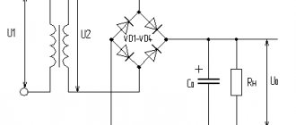
For example, the power supply, which has already been discussed on the pages of the site, contains a single-phase full-bridge rectifier - a diode bridge. In the circuit diagram, the diode bridge is depicted as follows.
Diode bridge circuit
This is a so-called single-phase bridge rectifier, one of several types of rectifiers that are actively used in electronics. It is used to produce full-wave rectification of alternating current.
In hardware it looks like this.
Diode bridge made of individual diodes S1J37
This circuit was invented by the German physicist Leo Graetz, therefore this circuit solution is sometimes called the “Graetz circuit” or “Graetz bridge”. In electronics, this circuit is currently used everywhere. With the advent of cheap semiconductor diodes, this circuit began to be used more and more often. Now you won’t surprise anyone with it, but in the era of radio tubes the “Graetz bridge” was ignored, since it required the use of as many as 4 tube diodes, which were quite expensive at that time.
Calculation of a bridge rectification circuit
The specified or known values are the voltage at the load (Uav.set, current through the load Iav, ripple factor of the rectified voltage Kp.set at the output, voltage and frequency of the supply network.
The calculated values are determined by the formulas:
A valve with permissible reverse voltage is selected from the directory
Urev ≥ 1.6 Uav.r
and current through the valve
I'avg ≥ 0.6Iavg
Next, the electrical quantities characterizing the secondary winding of the transformer are calculated:
UII=(1.1÷1.3)Uav.r III = 0.8Iav; PII=UIIII
In order to obtain a flat external characteristic, it is advisable to choose a filter starting with inductance.
Voltage ripple coefficient at the filter input
Kp.in = 0.67.
Smoothing factor
At a load current of up to 200 mA, the capacitance value of the filter link does not exceed 8–12 μF. Having specified the filter link capacitance Cf, we can determine the inductance of the filter choke
(208)
The capacitance of capacitor C1 shunting the inductor is calculated by the formula
(209)
Capacitor C1 must be designed for operating voltage
Uwork = 4πƒLдрIср
In conclusion, you need to determine the calculated (overall) power of the power transformer using the formula
History of creation
In 1873, British scientist Frederick Guthrie proposed a rectification circuit based on the use of vacuum diodes. The following year, 1874, Karl Ferdinand Braun from Germany invented the solid-state point rectifier.
In 1904, John Flemming created a high-quality tube diode, which later served as the basis for the creation of the devices in question. 2 years later, a crystal detector was invented. In the thirties, active research was carried out on the effects that occurred at the interface between crystals and metal parts. Based on them, the phenomenon of pn transition was discovered in 1939. At the same time, the influence of certain impurities on the type of conductivity (electronic or hole) was revealed.
The rectifier bridge in the form in which it is now known was created by the Polish electrical engineer Karol Pollak. Later, but independently of him, the same discovery was made by Leo Graetz. Sometimes in technical literature the name given in honor of the latter is used - the Graetz circuit.
In conclusion, it should be said that the principle of constructing a rectifying device can be used in very different ways. But any of them provides an output voltage that can only be called constant conditionally. The rectifier produces a unidirectional pulsating voltage. In most cases, it needs to be smoothed with filters.
Using Op Amps
As is known, the current-voltage characteristic of diodes is nonlinear; by creating a single-phase precision (high-precision) full-wave rectifier on an op-amp chip, the error can be significantly reduced. In addition, it is possible to create a converter that allows you to stabilize the current on the load. An example diagram of such a device is shown below.
Circuit: a simple op-amp stabilizer
The figure shows a simple current stabilizer. The op amp used in it is a voltage controlled source. This implementation makes it possible to ensure that the current at the output of the converter does not depend on the voltage loss across the load Rн and the diode bridge D1-D4.
If voltage stabilization is required, the converter circuit can be slightly complicated by adding a zener diode to it. It is connected in parallel to the smoothing capacitance.
Comparison of single-phase and three-phase devices
When comparing three-phase rectification circuits with single-phase analogues, it is important to note the following points:
- the first are used only in 380 Volt power networks, and the second type can be installed in both single-phase and three-phase circuits (one for each phase);
- 380 Volt rectifiers allow you to convert high power and develop significant currents in the load;
- on the other hand, making a three-phase rectifier yourself is somewhat more difficult, since it consists of a larger number of components.
It is not difficult to understand the essence of the operation of a three-phase rectifier. To do this, you will need to familiarize yourself with the basics of operation of valve devices and analyze the electrical circuit of their connection. Knowledge of the operating principle of rectifier devices will help the user to use it more effectively in everyday work.
Sources
Source - https://amperof.ru/elektropribory/dvuxpoluperiodnyj-vypryamitel.html Source - https://www.joyta.ru/12295-princip-raboty-odnofaznogo-dvuxpoluperiodnogo-vypryamitelya-so-srednej-tochkoj/ Source - https://electricalschool.info/electronica/2293-dvuhpoluperiodnyy-vypryamitel-so-sredney-tochkoy.html Source - https://ikit.edu.sfu-kras.ru/CP_Electronics/pages/mm/1_2/index.html Source - https://go-radio.ru/vipramiteli.html Source - https://studfile.net/preview/1802278/page:6/ Source - https://microtechnics.ru/diodnyj-most-i-dvuhpoluperiodnyj -vypryamitel/ Source - https://infopedia.su/3x14d.html Source - https://intellect.icu/dvukhpoluperiodnyj-mostovoj-vypryamitel-skhema-ponyatie-printsip-raboty-284 Source - https://strojdvor.ru /elektrosnabzhenie/princip-dejstviya-i-sxema-trexfaznogo-mostovogo-vypryamitelya/
General characteristics of rectifier diodes.
Depending on the value of the maximum permissible forward current, rectifier diodes are divided into small
,
medium
and
high
power:
low power
designed for direct current rectification up to 300mA;
average power
– from 300mA to 10A;
high power
- more than 10A.
According to the type of material used, they are divided into germanium
and
silicon
, but today
silicon
rectifier diodes are most widely used due to their physical properties.
Silicon diodes, compared to germanium diodes, have many times lower reverse currents at the same voltage, which makes it possible to obtain diodes with a very high permissible reverse voltage, which can reach 1000 - 1500V, whereas for germanium diodes it is in the range of 100 - 400V .
The performance of silicon diodes remains at temperatures from -60 to +(125 - 150)º C, and germanium diodes - only from -60 to +(70 - 85)º C. This is due to the fact that at temperatures above 85º C the formation of electronic hole pairs becomes so significant that there is a sharp increase in the reverse current and the efficiency of the rectifier decreases.