Operating principle
The operating principle is based on tracking circuit pulses. Current is supplied to the probe and applied to the contact. The indicator part monitors the voltage level and sends a signal to the control board. The models use an insulating part to ensure safety during operation.
Pointer Operation
The probe or tip can be connected to a flexible wire or tube. When the voltage exceeds the permissible limits, the indicator may not respond. There are models with and without a screen. Simple options are used with LED lamps.
Application area
The equipment is in demand at enterprises that use high voltage installations. Most often this is necessary at substations. Thus, there is a need to carry out phasing taking into account the voltage class. It is also possible to test cables and individual power lines.
Power lines
Interesting! It is allowed to check DC and AC transformers.
COMPOSITION AND DEVICE
High voltage indicator IVN-10 contains:
- Support insulators with built-in capacitive high voltage sensors with connecting wires in the amount of 3 pcs. (Fig. 1);
- display blocks in the amount of 3 pcs. (Fig. 2).
The high voltage sensor is capacitive type (Fig. 1), built into the support insulator. The support insulator is mounted on a traverse or wall. The signal from the sensor is output from the base of the support insulator by a wire in high voltage insulation. The sensors are supplied with a 2 m long wire or as agreed with the consumer. The display blocks (Fig. 2) contain gas-discharge type light elements. On the back side of the block there are sockets with fixing screws for connecting wires from the sensor and a ground wire with a terminal. The indication blocks are fastened “flush” on grounded structures (facade panels of installations, etc.), with two MZ screws for each block.
High voltage indicator device
The main elements of the index are:
- tip or probe,
- insulation,
- restrictor ring,
- handle,
- thread,
- indicator part.
In some cases, a display and contact stabilizers are used. The probe can be installed on a wire or holder. Indication can be visual or audio.
Display system
Rules of application
Before using the device, it is recommended to check the contents. Using the example of UVNU - 10SZ IP, the tube, insulation, and handle are inspected. The nodes must be securely connected; screw fastenings are used. A holder is fixed to the phasing tube. The ring stop must be attached to the body.
You may be interested in this Rating of the best soldering stations
Important! External inspection is necessary in order to identify cracks or peeling.
Pointer Defects
Any defects in the pointer indicate that it is not ready for use. If drops of water or dirt are found on the ring or tube, they must be removed. For this purpose, it is better to use a napkin. The device should be stored in a dry place, preferably protected from ultraviolet exposure.
Particular attention is paid to the hook-shaped probe. It must be examined without gloves and touched. The indicator that the device is on should light intermittently. If you hear sound, it means the device is working properly. In this way, the skin resistance is assessed and the test is completed.
If the pointer does not respond to human touch, you can try moistening your fingers a little. At sub-zero temperatures, devices operate with a large error. It is especially problematic to carry out work at temperatures of −20 degrees or more. It is recommended to select a guaranteed voltage source for the test. The presented indicator records readings from 100 to 1000 volts.
Voltage source
Important! You must hold the handle during the test.
When the probe is brought in, it must come into contact with the core. Under normal conditions, a person will hear an intermittent beep. The light will blink. This confirms that the object is energized. The contact method is necessary to determine the phase.
When using signs, the electrician often has to stand on supports. It's good to have an insulating rod. When working with high-voltage equipment, it is better to use workpieces at least 6 m long. The head is necessary for grounding. Touching live parts is sometimes accompanied by a bright light and a powerful sound signal.
Live parts
Before checking the grounding in the installation, measure the voltage. The permissible level of energy flow is 1.5 kV. If the indication does not respond, you must touch the indicator with your non-gloved hand. When the cable is under induced voltage, the indication operates in constant mode. Sometimes it is necessary to determine the phase, then a working tube is used. It connects to the pointer, as well as the pin.
To make the connection, the shunt is inserted into the hole. There are marks on the indicator; you should not make significant physical efforts. A separate issue concerns operational activities related to testing. The rules are specified in the electrical installation instructions.
You may be interested in this Features of crimping pliers
Electrical installations
Test objectives:
- determining the minimum level of indicator activation,
- longitudinal insulation test,
- maximum threshold test
For testing, the pointer is suspended indoors on a hill. The contact probe should be at the bottom. First of all, a slight voltage is applied to the hook; it is important to monitor the light bulb. The maximum limit of the presented modification is 1.5 kW. The longitudinal insulation test allows you to determine the permissible voltage level.
Longitudinal insulation test
Important! The device in good condition can withstand a load of 12 kV.
In this case, the voltage supply time is important. The phasing tube is checked in a similar way. For this purpose, a conductive part with a voltage of 12 kV is supplied. However, when the phase is turned on oppositely, the parameter is different. It all depends on the resistance of the conductor.
An indication with a tube attached to the pointer is triggered at a load of 1.5 kV. Using the example of UVNsTF 10I, it can be seen that simple options with a phasing tube are easier to use. The model is suitable for testing cable and overhead lines. When testing electrical installations, it is important to check the serviceability of transformers.
Transformers test
The permissible operating voltage must be in the range of 6-10 kV. The indicator phasing tube can only be used in an alternating current circuit. The permissible frequency is from 50 megahertz. As the manufacturer indicates, the maximum load level is 15 kV. When using the model, contact tips and electrical circuit elements are connected.
Interesting! The indicator has two connecting wires, as well as insulation.
The rod is installed between the bushings, fastening occurs due to a threaded connection. The presented model has a three-digit display and uses LED bulbs. When voltage is applied to the hook, they light up. It also triggers if testing is performed.
The indicator is capable of functioning in self-monitoring mode. In this case, the circuit checks the health of the nodes and reports possible errors. When the device is switched to operating mode, it becomes possible to automatically determine the type of voltage. Contact with the current-carrying conductor is ensured by the tip. Determining polarity does not take much time.
Interesting! The “-” LED is activated when a negative voltage is detected in the current-carrying part. A decrease in frequency is accompanied by flickering of the light bulb.
Flickering on the indicator
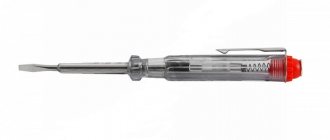
Description and principle of operation
The high and low voltage indicator is a universal portable device designed to determine the voltage on live wires or terminals of individual electrical devices (UVN 10, UNK, UVNK-10, BN-020022 Profipol Benning and others).
This device is necessary when working at various enterprises or when electricians travel to the site. The main difference between this indicator and standard meters is that it will help determine only the presence of a load, but not its indicators, unlike models that are mounted on a DIN rail.
Photo - indicator with digital display
Basically, only voltage devices up to 1000 Volts are now used; such an indicator can be bipolar or single-pole; they have a similar circuit, but different areas of application. During operation, devices with two poles must be connected to two current-carrying conductors or contacts, while single-pole devices must be connected to only one. You should know that two-pole indicators are more accurate, which is why they are called high-voltage and are used during complex work.
Photo - UN PIN-90
In addition to this, there is also a contactless pointer. Testing with its help is carried out without connecting to live terminals. This significantly increases safety during voltage determination. The device is equipped with a digital display, and it indicates not only the presence of voltage, but also the approximate size due to the magnetic field.
Photo - single-pole model
There are portable battery-powered models and options that require connection to the network (for example, a pointer or voltage indicator of the Kontakt 55EM type, UVNU-10 kV SZIP, ELIN-1-SZ VL). In the first case, power is provided using two or more batteries, less often from a battery (these are UVNK, UNNO, UNK, EI-9000/1, Duspol digital LC, Raton). This allows you to use the device on site, when traveling or for repair work far from the working power supply network.
Photo - imported UN DT-9902
The operating principle of the device is quite simple. During connection to the network (by connecting to live parts), a comparison of potentials is made. This increases or decreases the resistance in the pointer resistors. This causes the indicator, which draws the smallest fraction of the amps flowing in the wires or terminals, to light up or beep. If the indicator is silent during operation, then there is no load. In some cases, a systematic attenuation of the signal is observed - this means that there was residual energy in the wires.
Requirements for voltage indicators GOST 20493-2001:
- For devices up to 1000 Volts, the indicator load must be no higher than 90 V;
- A single-pole device is located in one housing, while a two-pole device is located in two, connected by a cord;
- Any indicator of the presence of a load (on-board, combi and others) must have three surfaces: working, insulated, defining and holder;
- In some models, the working part is connected to the indicator;
- The indicators are checked each time before use using a voltage of 2 kV, and it lasts no more than a minute.
It must be remembered that the safety instructions require full preparation before using the device. In particular, it is necessary to wear an energy kit, including dielectric gloves and boots. These requirements are specified for an electrical device, and they differ from the indicator models in UAZ, VAZ and other cars, ships, etc.
Video: UT 15V voltage indicator
Security measures
Basic Rules:
- use of electric gloves,
- contact is made to the working part,
- rod insulation,
- Do not use in the rain,
- compliance with GOST 20493-2001 standards.
You might be interested in Cable cutting tools
Voltage indicators above 1000 V are discussed above. The differences lie in the design and technical characteristics. For devices, the rules of use and precautions are specified in the instructions.
Voltage indicators above 1000 V
2.4.3. Voltage indicators above 1000 V react to capacitive current flowing through the indicator when its working part is introduced into the electric field formed by live parts of electrical installations that are energized, and the “ground” and grounded structures of electrical installations.
2.4.4. The indicators must contain the main parts: working, indicator, insulating, and also a handle.
2.4.5. The working part contains elements that react to the presence of voltage on the controlled current-carrying parts.
The housings of the working parts of voltage indicators up to 20 kV inclusive must be made of electrical insulating materials with stable dielectric characteristics. The housings of the working parts of voltage indicators of 35 kV and above can be made of metal.
The working part may contain an electrode tip for direct contact with the controlled current-carrying parts and not contain an electrode tip (non-contact type indicators).
The indicator part, which can be combined with the working part, contains elements of light or combined (light and sound) indication. Gas-discharge lamps, LEDs or other indicators can be used as light indication elements. Light and sound signals must be reliably recognizable. The audio signal should have a frequency of 1 - 4 kHz and a chopping frequency of 2 - 4 Hz when indicating phase voltage. The sound signal level must be at least 70 dB at a distance of 1 m along the axis of the sound emitter.
The working part may also contain a body for its own serviceability monitoring. Control can be carried out by pressing a button or be automatic by periodically sending special control signals. In this case, it must be possible to fully check the serviceability of the electrical circuits of the working and indicator parts.
Working parts must not contain switching elements intended for turning on power or switching ranges.
2.4.6. The insulating part of the signs must be made of the materials specified in clause 2.1.2.
The insulating part can be composed of several links. To connect the links to each other, parts made of metal or insulating material can be used. It is permissible to use a telescopic design, but spontaneous folding must be prevented.
2.4.7. The handle can be one piece with the insulating part or be a separate link.
2.4.8. The design and weight of the signs must ensure that one person can operate them.
2.4.9. The electrical circuit and design of the indicator must ensure its operability without grounding the working part of the indicator, including when checking the absence of voltage, carried out from telescopic towers or from wooden and reinforced concrete supports of 6 - 10 kV overhead lines.
2.4.10. The minimum dimensions of the insulating parts and handles of voltage indicators above 1000 V are given in table. 2.4.
- Table 2.4. Minimum dimensions of insulating parts and handles for voltage indicators above 1000 V
MINIMUM DIMENSIONS OF INSULATED PARTS AND HANDLES
VOLTAGE INDICATORS ABOVE 1000 V
┌─────────────────────────┬────────────── ───────── ───────────────┐ │ Rated voltage │ Length, mm │ │ electrical installations, kV ├───────────── ──────┬─ ─────────────────┤ │ │ insulating part │ handle │ ├────────────── ────────── ─┼───────────────────┼──────────────────┤ │From 1 to 10 │ 230 │ 110 │ │More │ └────────────── ───────────┴───────────────────┴───────── ───────── ┘
2.4.11. The voltage indicator indication voltage should be no more than 25% of the rated voltage of the electrical installation.
For indicators without a built-in power supply with a pulse signal, the indication voltage is the voltage at which the signal interruption frequency is at least 0.7 Hz.
For indicators with a built-in power supply with a pulse signal, the indication voltage is the voltage at which the signal interruption frequency is at least 1 Hz.
For other indicators, the indication voltage is the voltage at which there are distinct light (light and sound) signals.
2.4.12. The time for the first signal to appear after touching a live part under voltage equal to 90% of the rated phase voltage should not exceed 1.5 s.
2.4.13. The working part of the indicator for a certain voltage should not respond to the influence of neighboring circuits of the same voltage, spaced from the working part at the distances indicated in the table. 2.5.
- Table 2.5. Distance to the nearest wire of an adjacent circuit
DISTANCE TO THE CLOSEST WIRE OF THE NEIGHBORING CIRCUIT
┌─────────────────────────┬────────────── ───────── ───────────────┐ │ Rated voltage │Distance from the indicator to the nearest │ │ electrical installation, kV │ wires of the adjacent circuit, mm │ ├────── ────── ─────────────┼─────────────────────────── ───────── ──┤ │Above 1 to 6 │ 150 │ │Above 6 to 10 │ 220 │ │Above 10 to 35 │ 500 │ │110 │ 1500 │ │150 │ 1800 │ │220 │ 2500 │ └─────── ──────────────────┴────────────────────── ───────── ───────┘
2.4.14. During operation, mechanical tests of voltage indicators are not carried out.
2.4.15. Electrical tests of voltage indicators consist of testing the insulating part with increased voltage and determining the indication voltage.
Testing of the working part of voltage indicators up to 35 kV is carried out for indicators of this design, during operations with which the working part can cause a phase-to-phase short circuit or a phase-to-ground fault. The need to test the insulation of the working part is determined by the operating manuals.
For voltage indicators with a built-in power source, its condition is monitored and, if necessary, the batteries are recharged or the batteries are replaced.
2.4.16. When testing the insulation of the working part, voltage is applied between the tip electrode and the screw connector. If the indicator does not have a screw connector electrically connected to the indication elements, then an auxiliary electrode for connecting the test installation wire is installed at the boundary of the working part.
2.4.17. When testing the insulating part, voltage is applied between the element of its articulation with the working part (threaded element, connector, etc.) and a temporary electrode placed at the restrictive ring on the side of the insulating part.
2.4.18. The indication voltage of indicators with a gas-discharge indicator lamp is determined according to the same scheme by which the insulation of the working part is tested (clause 2.4.16).
When determining the indication voltage of other indicators that have an electrode tip, it is connected to the high-voltage terminal of the testing installation. When determining the indication voltage of indicators without a tip electrode, it is necessary to touch the end side of the working part (head) of the indicator to the high-voltage terminal of the test installation.
In both of the latter cases, the auxiliary electrode is not installed on the pointer and the grounding terminal of the test setup is not connected.
The voltage of the test installation smoothly rises from zero to the value at which the light signals begin to meet the requirements of clause 2.4.11.
2.4.19. The standards and frequency of electrical tests of indicators are given in Appendix 7.
2.4.20. Before you start working with the pointer, you need to check its serviceability.
The serviceability of indicators that do not have a built-in monitoring device is checked using special devices, which are small-sized sources of increased voltage, or by briefly touching the electrode-tip of the indicator to live parts that are known to be energized.
The serviceability of indicators with a built-in control unit is checked in accordance with the operating manuals.
2.4.21. When checking the absence of voltage, the time of direct contact of the working part of the indicator with the controlled current-carrying part must be at least 5 s (in the absence of a signal).
It should be remembered that although some types of voltage indicators can signal the presence of voltage at a distance from live parts, direct contact with them by the working part of the indicator is mandatory.
2.4.22. In electrical installations with voltages above 1000 V, the voltage indicator should be used with dielectric gloves.
<< Previous page ++ Table of contents ++ Next page >>