Definition 1
An electrical circuit is a collection of different devices that are connected in a specific way. Devices must provide a path for electrical current to flow. There are various circuit elements that serve a variety of purposes. To describe circuits, special electrical diagrams are used.
Any electrical circuit includes various elements:
- Current source. For example, it could be an inductor through which current from an external source flowed for some time.
- Conductors;
- Load (in the case when it is constant, the current-voltage characteristic curve is a straight line, and such a load is called linear;
- Protection devices;
- Switching devices.
Are you an expert in this subject area? We invite you to become the author of the Directory Working Conditions
There are two types of circuit elements: passive and active. Passive elements are connecting elements and devices that consume electricity; passive elements also include capacitors. Active elements are electric motors, charging batteries and various sources of EMF.
The main types of electrical circuit are:
- closed circuit;
- open circuit.
Electrical circuits
An electrical circuit is a collection of devices through which electric current flows.
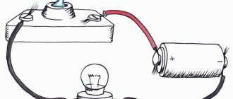
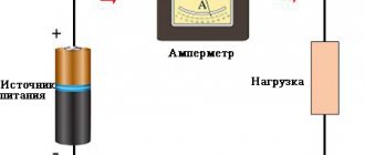
Let's consider the simplest electrical circuit. What does it consist of? It has a generator - a current source, a receiver (for example, a light bulb or an electric motor), and a transmission system (wires). For a circuit to become a circuit, and not a set of wires and batteries, its elements must be connected to each other by conductors. Current can only flow through a closed circuit. Let's give one more definition:
An electrical circuit is a current source, transmission lines and a receiver connected to each other.
Of course, source, receiver and wires are the simplest option for a basic electrical circuit. In reality, different circuits include many more elements and auxiliary equipment: resistors, capacitors, switches, ammeters, voltmeters, switches, contact connections, transformers, etc.
Electrical circuit
By the way, read about what a transformer is in a separate article on our blog.
By what fundamental characteristic can all electric current circuits be divided? Same as current! direct circuits , and there are alternating current circuits . In a direct current circuit, it does not change its direction; the polarity of the source is constant. Alternating current changes periodically over time, both in direction and in magnitude.
Nowadays alternating current is used everywhere. Read about what Nikola Tesla did for this in our article.
Resistance
The diagram from the previous section is not very practical. In fact, assembling it (directly connecting the poles of a voltage source using only a piece of wire) can be quite dangerous. The reason this is dangerous is that in such a short circuit the amount of electrical current can be very large and the energy released can be very significant (usually in the form of heat). Typically, in practice, electrical circuits are designed in such a way as to make maximum safe use of the released energy.
Elements of electrical circuits
All elements of electrical circuits can be divided into active and passive. The active elements of the circuit are those elements that induce EMF. These include current sources, batteries, and electric motors. Passive elements – connecting wires and electrical receivers.
Receivers and current sources, from the point of view of circuit topology, are two-pole elements (double-terminal). To operate, they require two poles through which they transmit or receive electrical energy. Devices through which current flows from a source to a receiver are four-terminal. To transfer energy from one two-terminal network to another, they need at least 4 contacts, respectively for receiving and transmitting.
Resistors are elements of an electrical circuit that have resistance. In general, all elements of real circuits, down to the smallest connecting wire, have resistance. However, in most cases this can be neglected and the elements of the electrical circuit can be considered ideal when calculating.
There are symbols for depicting circuit elements in diagrams.
By the way, read more about current strength, voltage, resistance and Ohm’s law for elements of an electrical circuit in a separate article.
Current-voltage characteristic is a fundamental characteristic of circuit elements. This is the dependence of the voltage at the terminals of the element on the current that passes through it. If the current-voltage characteristic is a straight line, then the element is said to be linear. A circuit consisting of linear elements is a linear electrical circuit. A nonlinear electrical circuit is a circuit in which the resistance of sections depends on the values and direction of the currents.
What are the ways to connect elements of an electrical circuit? No matter how complex the circuit is, the elements in it are connected either in series or in parallel.
When solving problems and analyzing circuits, the following concepts are used:
- A branch is a section of a circuit along which the same current flows;
- Knot – connection of chain branches;
- A circuit is a sequence of branches that forms a closed path. In this case, one of the nodes is both the beginning and the end of the path, and the other nodes appear in the circuit only once.
To understand which is which, let's look at the picture:
By the way! For our readers there is now a 10% discount on any type of work
Current flowing through the lamp filament
One of the practical and popular uses of electric current is electric lighting. The simplest form of electric lamp is a tiny metal "filament" inside a clear glass bulb that becomes white-hot with thermal energy when enough electric current is passed through it. Like a battery, it has two conductive connection points: one for current input and one for current output. The circuit of an electric lamp connected to a voltage source looks something like this:
Figure 1 – Current through the lamp
When current passes through a thin metal filament of a lamp, it encounters more resistance to movement than in a regular thick piece of wire. This resistance to electric current depends on the type of material, its cross-sectional area and temperature. Technically, this opposition is known as resistance (conductors can be said to have low resistance, while dielectrics have very high resistance). This resistance serves to limit the amount of current flowing through the circuit for a given voltage supplied by the battery, compared to a "short circuit" where we had nothing but a wire connecting one end of the voltage source (battery) to the other. When current moves against the opposition of resistance, "friction" occurs. As with mechanical friction, friction created by current flowing through a resistance manifests itself as heat. The concentrated resistance of the lamp filament causes a relatively large amount of thermal energy to be dissipated into the filament. This thermal energy is enough to cause the filament to become white-hot and begin to glow, while the wires connecting the lamp to the battery (which have much less resistance) are unlikely to become even warm while carrying the same amount of current. As in the case of a short circuit, if the continuity of the circuit is broken at any point, the current stops throughout the circuit. When the lamp is installed, this means that it will stop glowing:
Figure 2 - No current flows through the lamp
Classification of electrical circuits
According to their purpose, electrical circuits are:
- Power electrical circuits;
- Electrical control circuits;
- Electrical measurement circuits;
Power circuits are designed to transmit and distribute electrical energy. It is the power circuits that conduct current to the consumer.
Circuits are also divided according to the current strength in them. For example, if the current in the circuit exceeds 5 amperes, then the circuit is power. When you click a kettle plugged into a socket, you close a power electrical circuit.
Electrical control circuits are not power and are designed to activate or change the operating parameters of electrical devices and equipment. An example of a control circuit is monitoring, control and signaling equipment.
Electrical measurement circuits are designed to record changes in the operating parameters of electrical equipment.
Basis for switching lamps
What we see here is the basis for turning lamps on and off with remote switches. Since any violation of the continuity of the circuit leads to the cessation of current flow throughout the circuit, then to control the flow of current in the circuit we can use a device designed to deliberately disrupt this continuity (called a key, or switch, switch, etc.) and installed in any convenient place to which we can run the wires:
Figure 3 - Adding a key to the circuit of battery and lamp
Thus, a switch mounted on the wall of the house can control a lamp installed in a long hallway or even in another room, far from the switch. The key itself consists of a pair of conductive contacts (usually made of some kind of metal) connected by a mechanical lever or button. When the contacts touch each other, continuity is established and current can flow from one contact to the other. When the contacts are separated, the flow of current from one to the other is prevented by the air insulation between them, and the continuity of the circuit is broken.
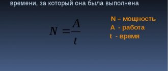
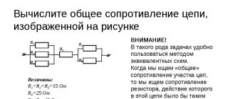
Calculation of electrical circuits
To calculate a circuit means to find all the currents in it. There are different methods for calculating electrical circuits: Kirchhoff's laws, the loop current method, the nodal potential method and others. Let's consider the application of the loop current method using the example of a specific circuit.
First, we select the contours and designate the current in them. The direction of the current can be chosen arbitrarily. In our case - clockwise. Then for each circuit we will compose equations according to Kirchhoff’s 2nd law. The equations are composed as follows: The circuit current is multiplied by the circuit resistance, and the products of the current of other circuits and the total resistance of these circuits are added to the resulting expression. For our scheme:
The resulting system is solved by substituting the initial data of the problem. We find the currents in the branches of the original circuit as the algebraic sum of the loop currents
Whatever circuit you need to calculate, our specialists will always help you cope with the tasks. We will find all currents using Kirchhoff's rule and solve any example of transient processes in electrical circuits. Enjoy your studies with us!
Blade switch
Perhaps the best type of switch to illustrate the principle of operation is the blade type switch:
Figure 4 – Knife type switch
A knife switch is nothing more than a conductive arm that is free to pivot on a hinge, making physical contact with one or more fixed contacts that are also conductive. The switch shown in the above picture is assembled on a porcelain base (an excellent insulating material), using copper (an excellent conductor) for the "blade" and contacts. The handle is made of plastic to isolate the operator's hand from the conductive blade of the switch when opening or closing it. Below is another type of switch, with two fixed contacts instead of one:
Figure 5 – Knife-type switch with 3 contacts
The blade switch shown here has one "blade" and two fixed contacts, meaning it can turn more than one circuit on or off. At this point it's not that important to just understand the basic idea of what a key is and how it works. Knife switches are great for illustrating the basic principle of a switch, but they present certain safety concerns when used in high power electrical circuits. The exposed switch conductors make accidental contact with the circuit very possible, and any spark that may occur between the moving blade and the stationary contact can ignite any flammable materials nearby. Most modern switch designs enclose the moving conductors and contacts with an insulating casing to reduce these hazards. Photographs of several modern types of switches show that the switching mechanisms are much more hidden than in the blade switch design:
Figure 6 - Comparison of switch sizes