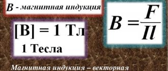
Definition
The scientist who discovered this law is a real mystery of history: all that is known about him is that his last name was Buravchik. Most are inclined to believe that his name was Pyotr Sigismundovich. Many stories are written about him. Even with the advent of the gimlet law, there is a funny half-joke, half-legend associated: supposedly when gimlet was able to formulate this rule (though the name was not in honor of its author, but in honor of those objects that operated in accordance with this law), he went straight to Moscow to bow to Mikhail Vasilyevich Lomonosov. The simplicity of the method somewhat confused the great scientist, and he, lost in thought, turned away and began, excuse the expression, to pick his nose. To which Pyotr Sigismundovich sarcastically remarked that Mikhail Vasilyevich, using his finger as a gimlet, followed his law exactly. After this, Lomonosov no longer hesitated in making a decision regarding Buravchik’s research: the rule is to be! Each physicist formulates this rule in his own words, but the essence is always this: if the direction of movement of the corkscrew passes in the same direction as the direction of the current inside the conductor, then its handle will demonstrate the direction in which the magnetic induction vector will be turned. In turn, the corkscrew was interpreted into a right-hand rule, which in turn served as the basis for another mnemonic law, the left-hand rule, which makes physics seem much simpler. All of them are actively used in many areas - in this a significant role is played by their simplicity coupled with efficiency, which were noted by Lomonosov, as well as the fact that they sound concisely and clearly: using the gimlet rule, you can determine, for example, the side in which the angular velocity, magnetic induction, parameters of the induction current and much more are directed, which allows you to solve problems. In this article we will look in detail at all cases of these rules and the screw rule.
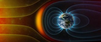
Earth's magnetic field
The Earth is not only a large negative charge and a source of electric field, but at the same time the magnetic field of our planet is similar to the field of a direct magnet of gigantic proportions.
Geographic south is close to magnetic north, and geographic north is close to magnetic south. If a compass is placed in the Earth's magnetic field, then its north arrow is oriented along the lines of magnetic induction in the direction of the south magnetic pole, that is, it will show us where the geographic north is located.
The characteristic elements of the earth's magnetism change very slowly over time - secular changes
. However, from time to time magnetic storms occur, when the Earth's magnetic field is greatly distorted for several hours and then gradually returns to its previous values. Such a drastic change affects people's well-being.
The Earth's magnetic field is a “shield” that protects our planet from particles penetrating from space (“solar wind”). Near the magnetic poles, particle flows come much closer to the Earth's surface. During powerful solar flares, the magnetosphere is deformed, and these particles can move into the upper layers of the atmosphere, where they collide with gas molecules, forming auroras.
General main rule
The rule has several variations used for special cases. However, the main option can be used for many cases. It is most convenient to use a positive vector in the vector product and a right ordered triple in the basis. With this approach, the factors will have a positive sign and you won’t have to consider where to put a minus and where not. A right basis is an ordered triple of vectors arranged so that the shortest path in order is counterclockwise. If three fingers (except for the little finger and ring finger) are placed perpendicular to each other and taken as the Ox, Oy, Oz axes for the middle, index and thumb, respectively, then a right basis will be obtained. The choice of a positive vector or basis is preferable due to the convenience of calculations. But it is also possible to use the left basis. For example, it is chosen for tasks in which the use of a positive value is impossible.
For a cross product
For him this is the rule:
- If you draw the vectors so that their initial coordinates coincide;
- And also start torsion of our first BC (vector-factor) to the second BC in the fastest way;
- Then our drill will screw towards the VP (product vector).
It is not difficult to notice how much the wording has changed: it has become noticeably more complex and is much harder to perceive without a picture than all the others. However, you can simplify your task somewhat and reformulate it using a clockwise direction:
- If you draw the vectors in such a way that their initial coordinates coincide;
- And also begin torsion of our first aircraft to the second in the fastest way and begin to observe from that angle so that this torsion is located clockwise for you;
- Then the VP will be directed away from you.
Using arrows makes everything a lot easier, doesn't it?
This material is enough for a complete understanding of the topic. In the next paragraph, I propose to consider how the same rule will look for bases, in particular, for the right one.
For bases
This rule will work almost similarly for bases. In the right basis, when the corkscrew is rotated, directed along one of the vectors, along the shortest path to the second vector, the twist of the tool will indicate the direction of the third vector. For ease of remembering, a wall clock is represented: two vectors are arrows, and the third is directed towards or away from the observer (the choice will determine the orientation of the entire basis, that is, it will be right or left).
The gimlet rule is universal and suitable for determining many vectors, since such laws often use bases and vector products that obey one specific law. Also used for Maxwell's equations, which describe the induction field in a continuous medium and its effect on point charged particles.
Physical meaning of magnetic induction
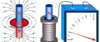
Physically, this phenomenon is explained as follows. The metal has a crystalline structure (the coil is made of metal). The crystal lattice of a metal contains electrical charges - electrons. If no magnetic influence is exerted on the metal, then the charges (electrons) are at rest and do not move anywhere.
Dmitry Petrovich VasilievProfessor of Electrical Engineering, St. Petersburg State Polytechnic University If the metal comes under the influence of an alternating magnetic field (due to the movement of a permanent magnet inside the coil - namely movement), then the charges begin to move under the influence of this magnetic field.
As a result, an electric current arises in the metal. The strength of this current depends on the physical properties of the magnet and coil and the speed of movement of one relative to the other.
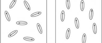
When a metal coil is placed in a magnetic field, the charged particles of the metal lattice (in the coil) are rotated at a certain angle and placed along the magnetic field lines.
The higher the strength of the magnetic field, the more particles rotate and the more uniform their arrangement will be.
Magnetic fields oriented in one direction do not neutralize each other, but add up, forming a single field.
Thumb and right hand rule for
Solenoid:
To avoid additional questions to the article, I will explain the meaning of this word in more detail: a solenoid is a wire spiral, sometimes represented as a coil with current, an integral part of many problems in physics and electrical engineering. For a solenoid, the right-hand rule can consist of several formulations, but, as a rule, it goes like this:
- If you hold the solenoid with your right hand;
- And after that, point four fingers along the current in the turns;
- Then it turns out that your thumb shows where the magnetic field voltage lines located inside the coil are directed.
As you can see, there is nothing complicated here. Therefore, I propose to consider other examples.
Magnetic field
The rule of the right hand for a magnetic field will sound like this: if you direct your thumb, bent 90 degrees from the others, along the movement of the conductor, and position your palm so that the field lines “enter” it, then the remaining fingers will coincide with the vector of the induced current.
Vector artwork:
This rule (in rewritten form) differs from the previous ones. It has two sound options. The first formulation of the right hand rule read:
- If you draw the vectors in such a way that their initial coordinates coincide when superimposed;
- Start rotating the first BC (multiplier vector) in the shortest way to the second BC;
- And also position all the fingers of your right hand (except for the thumb) so that they show the side in the direction of which the rotation occurred, as if you were squeezing a cylinder in your hand;
- Then your thumb will point in the direction of the VP (product vector).
The second formulation is often called a “pistol” and sounds like this:
- If you draw the vectors in such a way that their initial coordinates coincide when superimposed;
- Place your thumb in the direction of the first BC;
- Index - in the direction of the second sun
- Then and only then will your middle finger indicate the approximate direction of the VP.
This mnemonic rule is quite easy to remember as FBI - in English this abbreviation FBI:
- F is the force that flows parallel to the middle finger;
- B is the magnetic induction vector directed along the index
- I is the current flowing along the large one.
In addition, as I mentioned earlier, it is also called a “pistol”: it is easy to notice that your fingers will be positioned in the shape of a pistol when performing it.
This concludes our study of the right-hand rule, and we will turn to the third (and shortest) section of the article - the left-hand rule (LHR).
Lenz and Faraday's laws
The phenomenon of electromagnetic induction
Faraday's law shows the mathematical relationship of the most important parameters of this phenomenon:
E = - dФ/dt,
Where:
- E – EMF;
- Ф – flux formed by a magnetic induction vector penetrating through a limited contour;
- t – time.
In this expression, “-” before the main part denotes the rule formulated by E. Lenz. This Russian scientist found that the current in the circuit under consideration creates a field direction opposite to the force component of the magnetic flux.
For practical application, it is more convenient to express the above-mentioned patterns as follows:
E = -N*(dФв/dt).
This example shows an induction coil placed in a magnetic (alternating) field. Additional components:
- N – number of solenoid turns;
- Fv – flow through a single turn.
In the differential representation, this law is described by the integral over an arbitrary surface of the magnetic induction vector, which permeates an area with certain boundaries. This form allows you to take into account only field changes. Magnetic flux is a set of lines that pass through a certain area. To simplify calculations, it is assumed that the field is uniform.
Left hand rule for
The main difference between the rules of the right and left hands is in their purpose, as well as in the choice of palm. The left hand rule is used to determine the Ampere force and the Lorentz force, while the right hand can determine vectors of different quantities (for example, magnetic induction, angular velocity, torque).
Ampere forces, what is it?
The first rule of the left hand is associated with the power of Andre-Marie Ampère, which the French scientist discovered in 1820 - immediately after Ampère’s law. The principle of its operation is as follows:
- Place your left palm so that the magnetic field induction lines enter into its inner side perpendicular to it;
- Direct all fingers, except the thumb, through the electric current
- In this case, your left thumb, which should form a right angle with the rest, will show the direction of the force that will act from the magnetic field on the current-carrying conductor - that is, the Ampere force.
However, this is only one version of PLR.
Lorentz forces and differences from the previous one
The magnetic field force that acts on a charged particle of point size is called the Lorentz force. This quantity is necessary to complement Maxwell's equation and describe the behavior of the electromagnetic field and charged particles. Determine the direction using the rule for the left hand. This algorithm is performed in the following way. The fingers (except for the little and ring fingers) are placed perpendicular to each other (first the thumb and index in the form of the letter “L”, and then the middle one is set at right angles to both of them). The corresponding finger will indicate the direction:
- Lorentz forces are large;
- Magnetic lines - index;
- Toka - average.
The main difference is the position of the hand. Please note that in the previous case we used an open palm, and in this case only three fingers folded into a pistol.
Basic formulas for calculating the MI vector
The magnetic induction vector, the formula of which is B = Fm/I*∆L, can be found using other mathematical calculations.
Biot-Savart-Laplace Law
Induction EMF formula
Describes the rules for finding B→ magnetic field, which creates a constant electric current. This is an experimentally established pattern. Biot and Savard identified it in practice in 1820, Laplace managed to formulate it. This law is fundamental in magnetostatics. During the practical experiment, a stationary wire with a small cross-section was considered, through which an electric current was passed. For study, a small section of wire was selected, which was characterized by the vector dl. Its module corresponded to the length of the section under consideration, and its direction coincided with the direction of the current.
Interesting. Laplace Pierre Simon proposed to consider even the movement of one electron as a current and, based on this statement, using this law, he proved the possibility of determining the magnetic field of an advancing point charge.
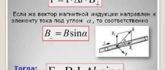
According to this physical rule, each segment dl of a conductor through which electric current I flows forms dB r and at an angle α :
dB = µ0 *I*dl*sin α /4*π*r2,
Where:
- dB – magnetic induction, T;
- µ0 = 4 π*10-7 – magnetic constant, H/m;
- I – current strength, A;
- dl – conductor section, m;
- r – distance to the point where the magnetic induction is located, m;
- α is the angle formed by r and the vector dl.
Important! According to the Biot-Savart-Laplace law, by summing the magnetic field vectors of individual sectors, it is possible to determine the MF of the desired current. It will be equal to the vector sum.
Biot-Savart-Laplace Law
There are formulas that describe this law for individual cases of MP:
- fields of direct movement of electrons;
- fields of circular motion of charged particles.
The formula for MP of the first type is:
B = µ* µ0*2*I/4*π*r.
For circular motion it looks like this:
B = µ*µ0*I/4*π*r.
In these formulas, µ is the magnetic permeability of the medium (relative).
The law under consideration follows from Maxwell's equations. Maxwell derived two equations for the magnetic field; the case where the electric field is constant is considered by Biot and Savart.
Superposition principle
For MF, there is a principle according to which the total vector of magnetic induction at a certain point is equal to the vector sum of all MI vectors created by different currents at a given point:
B→= B1→+ B2→+ B3→… + Bn→
Superposition principle
Circulation theorem
Initially, in 1826, Andre Ampère formulated this theorem. He analyzed the case with constant electric fields, his theorem is applicable to magnetostatics. The theorem states: the circulation of MF of direct electricity along any circuit is proportional to the sum of the forces of all currents that penetrate this circuit.
Worth knowing! Thirty-five years later, D. Maxwell generalized this statement, drawing parallels with hydrodynamics.
Another name for the theorem is Ampere’s law, which describes the circulation of MP.
Mathematically, the theorem is written as follows.
Mathematical formula of the circulation theorem
Where:
- B→– magnetic induction vector;
- j→ – electron motion density.
This is the integral form of writing the theorem. Here, on the left side one integrates along a certain closed contour, on the right side - along a stretched surface onto the resulting contour.
Magnetic flux
One of the physical quantities characterizing the level of magnetic field crossing any surface is magnetic flux. It is designated by the letter φ and has a unit of measurement called Weber (Wb). This unit is characteristic of the SI system. In the GHS, magnetic flux is measured in maxwells (Mks):
108 μs = 1 Wb.
Magnetic flux φ determines the magnitude of the magnetic field penetrating a certain surface. The flux φ depends on the angle at which the field penetrates the surface and the strength of the field.
The formula for calculation is:
φ = |B*S| = B*S*cosα,
Where:
- B is the scalar value of the magnetic induction gradient;
- S – area of the intersected surface;
- α is the angle formed by the flow Ф and the perpendicular to the surface (normal).
Attention! Flux Ф will be greatest when B→ coincides with the normal in direction (angle α = 00). Similar to Ф = 0, when it runs parallel to the normal (angle α = 900).
Magnetic flux
The magnetic induction vector, or magnetic induction, indicates the direction of the field. Using simple methods: the gimlet rule, a freely oriented magnetic needle or a circuit with a current in a magnetic field, you can determine the direction of action of this field.
Mechanical rotation
Important abbreviations: PB - gimlet rule, RS - angular velocity, RPR - right hand rule. The formulation of the PB for mechanical rotation is defined as follows: If you start screwing the drill in the direction in which the body is spinning, it will be twisted in the direction where the steering wheel tends. As expected, everything here is simple and clear. But PPR in mechanics is defined noticeably differently. This rule in this case looks and works like this:
- If you take an object in your right hand;
- Then you will begin to twist it in the direction in which all your fingers are pointing to you, except the thumb;
- Then the last remaining finger will indicate to us where the control system will tend during such rotation.
Absolutely, you can also find the side in which the angular momentum will be directed.
This was expected, because angular momentum is directly proportional to angular velocity with a positive (!) coefficient. It will look similar for the angular momentum. But let's return to our wonderful screw rule and see how this approach works for the moment of force.
Gimlet rule for moment
A moment of force is a vector of force that causes the rotational motion of an object. Torque is related to other quantities, such as the work done when a body rotates. Although the algorithm works in a similar way, let us formulate the screw (gimlet) rule for the moment of force. If you rotate the corkscrew to where the forces are displacing the body, then the direction in which the tool is screwed will indicate the direction of the torque. For the right hand, the rule sounds like this: mentally taking an object in the right hand, the object is moved in the direction of the four fingers (their orientation should coincide with the side where the forces are trying to move the object), while the straightened thumb will indicate the vector of the torque.
Determining the direction of current with a gimlet
As mentioned above, the direction of the current can be determined based on the PB. This is done as follows:
- Your right hand should take the guide;
- After this, you need to stick out four fingers in the direction of the magnetic field lines;
- Then your thumb raised up will indicate the direction of the electric current.
Quite convenient step-by-step instructions, isn’t it?
In addition, by reformulating our statement, we can determine the direction of the magnetic induction vector, which will be discussed in more detail in the paragraph below.
Magnetic properties of matter
\(~\mu = \frac{B}{B_0}\) ,
where μ
– magnetic permeability, tabular value;
B
– magnetic induction in the substance (T);
B
0 – magnetic induction of the external (magnetizing) field (T).
Then, taking into account the magnetic permeability of the medium
- magnetic field induction of an infinite straight conductor
with current at a distance
l
\(~B_{pr} = \frac{\mu \cdot \mu_0 \cdot I}{2 \pi \cdot l}\) ; - magnetic field induction in the center of the circular current
(
ring
) \(~B_{kr} = \frac{\mu \cdot \mu_0 \cdot I}{2 r}\) ; - magnetic field induction inside
(
middle
)
of a cylindrical coil
(solenoid) \(~B_c = \frac{\mu \cdot \mu_0 \cdot I \cdot N}{l}\) .
Determining the direction of the magnetic induction vector using the gimlet rule
To determine the direction of the magnetic induction lines, we do the following. Using the tip of a gimlet, we indicate the current vector, then the side into which the tool will twist will show the direction of magnetic induction for this conductor. The tool is produced with different twisting directions, so we assume that the traditional one, twisting to the right, is used. If you are used to the other option, you can imagine that the corkscrew is unscrewing. It’s the same with the right hand: if we imagine that the conductor under study is in the clasping right palm, and the thumb is directed in the direction of the flow of electric current, then the bent remaining fingers will coincide with the lines of magnetic induction.
A magnetic field
Already in the 6th century. BC. In China, it was known that some ores have the ability to attract each other and attract iron objects. Pieces of such ores were found near the city of Magnesia in Asia Minor, so they were called magnets
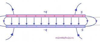
.
How do magnets and iron objects interact? Let's remember why electrified bodies are attracted? Because a peculiar form of matter is formed near an electric charge - an electric field. There is a similar form of matter around the magnet, but it has a different nature of origin (after all, the ore is electrically neutral), it is called a magnetic field
.
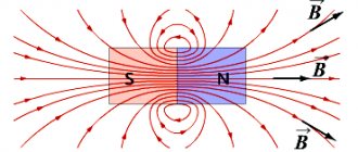
To study the magnetic field, straight or horseshoe magnets are used. Certain places of a magnet have the greatest attractive effect; they are called poles
(north and south)
. Opposite magnetic poles attract, and like magnetic poles repel.
For the strength characteristics of the magnetic field, use the magnetic field induction vector B
.
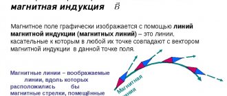
The magnetic field is graphically represented using lines of force ( magnetic induction lines
). Lines are closed, have neither beginning nor end. The place from which magnetic lines emerge is the North Pole; magnetic lines enter the South Pole.
The magnetic field can be made “visible” using iron filings.
Methods for determining the movement of electric current and magnetic field using the screw rule
In order for you to find the side towards which the magnetic field tends, or rather, magnetic lines near a conductor carrying current, the rule of the right screw was invented, which is defined as follows: if you start screwing in the gimlet according to the direction of the current in the conductor, then the side , into which the gimlet handle will rotate, will show us where the magnetic field lines will tend. But for electric current the rule is formulated somewhat differently:
- First, you should wrap your hand around the wire;
- Then you need to clench all your fingers, except the main one, into a fist;
- The thumb, which will need to be placed vertically, will show you the path of movement of the electric current.
So, we looked at the most important thing: the gimlet rule, the rule of the right and left hands. The last two points will complement our article and demonstrate special cases that will allow you to know the material flawlessly.
Lesson summary on the topic “Magnetic induction vector module. Ampere Power"
Item name:
"Physics".
Teacher
: Ph.D., Dolgova Valentina Mikhailovna
Class
: 11
UMK:
Physics. Grade 11. /G.Ya.Myakishev, B.B.Bukhovtsev, V.M.Charugin; ed. ON THE. Parfentyeva. – M.: Education, 2014.
Level of study
: basic.
Lesson topic:
“Magnetic induction vector module. Ampere power. Laboratory work No. 1 “Observation of the effect of a magnetic field on a current.”
Total number of hours allocated to study the topic: 12
Place of the lesson in the system of lessons on the topic:
Students were introduced to the concepts of “magnetic induction module” and “Ampere force” in the 9th grade. In the 11th grade, this lesson is assigned the role of deeper assimilation of knowledge, a high level of generalization and systematization.
The purpose of the lesson
: repetition and deepening of knowledge on the topic “Magnetic induction vector module. Ampere's power.
Lesson objectives:
- Didactic
– create conditions for mastering new educational material through a problem-based activity approach.
- Educational
– identify the quality and level of mastery of knowledge and skills previously acquired on this topic; repeat and deepen the understanding of the action of a magnetic field on a current-carrying conductor, the modulus of magnetic induction and the Ampere force, the determination of the Ampere force according to the left-hand rule; consider the manifestations of the action of a magnetic field on an electric current;
- Developmental
– develop students’ cognitive interest; develop the ability to analyze the phenomenon of the action of a magnetic field on a current-carrying conductor.
- Educational
– to foster a culture of academic work, self-education skills, and improve communication skills during joint work in the classroom.
Planned results:
Having worked through the material in this lesson, students should know and understand
:
phenomenon
the action of a magnetic field on a current-carrying conductor;
quantities:
magnetic induction module, Ampere force;
rule
left hand;
apply:
logical methods of cognition when solving problems to determine the Ampere force and the magnetic induction module and experimental methods of cognition when performing laboratory work.
Lesson technical support:
- Computer, projector, screen.
- Physics equipment:
power supply, rheostat, ammeter, wire, key, connecting wires, arc-shaped magnet.
Additional methodological and didactic support for the lesson:
Lesson content:
I. _ Checking homework using individual questioning.
1. Magnetic field and its properties.
2. Gimlet rule (direction of the magnetic induction vector)
3. Magnetic induction lines. Vortex field.
4. Checking the completion of quality tasks: p. 10, A1-A4.
(For each student who answers, classmates ask additional questions on the topic: “Interaction of currents. Magnetic field. Magnetic induction lines”)
Questions:
1.What forces are called magnetic?
2.How do conductors interact with current?
3. How are the properties of the magnetic field established?
4.List the properties of the magnetic field.
5. How does the magnetic field of a conductor act on a closed circuit with current?
6.What value characterizes the magnetic field at each point?
7.What direction is taken as the direction of the magnetic induction vector?
8. What is the gimlet rule?
9. What allows you to determine the right hand rule?
10. What fields are called vortex fields? What is the difference between a vortex field and a potential field?
II. Updating knowledge.
2.1. Historical reference
(prepared by student).
Andre Marie Ampère (1775-1836) - French physicist, mathematician, chemist, foreign member of the St. Petersburg Academy of Sciences (1830), one of the founders of electrodynamics.
An outstanding scientist, in whose honor one of the basic electrical quantities is named - the unit of current - ampere. The author of the very term “electrodynamics” as the name of the doctrine of electricity and magnetism, one of the founders of this doctrine.
Ampere's main works in the field of electrodynamics. He is the author of the first theory of magnetism. He proposed a rule for determining the direction of action of a magnetic field on a magnetic needle (Ampere's rule).
Ampere conducted a series of experiments to study the interaction between electric current and a magnet, for which he designed a large number of devices. Discovered the effect of the Earth's magnetic field on moving current-carrying conductors.
He discovered (1820) the magnetic interaction of currents and established the law of this interaction (Ampere's law). He argued that a large magnet consists of a huge number of elementary “flat magnets.”
Andre Marie Ampère discovered (1822) the magnetic effect of a current coil (solenoid). He expressed the idea of the equivalence of a current-carrying solenoid and a permanent magnet. He proposed placing a metal core made of soft iron to enhance the magnetic field. He expressed the idea of using electromagnetic phenomena to transmit information (1820). Ampère invented the commutator, the electromagnetic telegraph (1829).
2.2. Setting the goals and objectives of the lesson. Formulation of the lesson topic by students.
III . Learning new material.
3.1. Let's conduct a demonstration experiment
. We observe the action of a buoyant force on a conductor connected to a current source. As the current increases, the force acting on the conductor also increases. By changing the tilt of the stand on which the magnet is located, we made sure that the Ampere force also changed.
Thus, when studying a magnetic field using a straight conductor with current, we experimentally obtained formulas for determining magnetic induction: F = I· B· L· - Ampere's law.
The maximum Ampere force is calculated by the formula: Fm= I ·ΔL· B
B = F/IL; B= M/IS;
where F is the force with which the magnetic field acts on a current-carrying conductor (N);
I
– current strength (A);
L – conductor length (m); M – moment of force (Nm); S – area of the frame with current (m2). The unit of measurement of induction
is determined: 1N/ 1A · 1m =
1T (tesla)
3.2. Ampere force direction
determined using the left-hand rule.
We position the left hand so that the lines of magnetic induction enter the palm, and four extended fingers show the direction of the current in the conductor, then the thumb bent 90˚ will show the direction of the Ampere force.
3.3
.
Laboratory work on the topic “
Observation of the effect of a magnetic field on a current.”
Goal:
(formulate yourself).
Frontal conversation with students based on laboratory work material:
- Why is there a magnetic field near a permanent magnet?
- Why is it more clear to conduct experiments not with a single conductor, but with a coil of wire?
- How are magnetic fields represented?
- Which lines are used to graphically represent the magnetic field.
Equipment for laboratory work: arc-shaped magnet, coil of wire, tripod, rheostat, DC source, connecting wires, key.
Safety briefing for students.
Progress:
Before carrying out laboratory work, we will correctly place the instruments. We hang a coil of wire on a tripod, and then connect it to a current source in series with a rheostat (to increase the resistance) and a switch. We will set the rheostat motor to the highest resistance to prevent damage to the plastic ring on which the wire is wound. We close the key only during the experiment and immediately open it after the end of the experiment.
Independent experiment with the effect of a magnetic field on an electric current
1. We bring the arc-shaped magnet to a coil of wire hanging on a tripod, close the key, and observe the movement of the coil.
2. Let us draw 4 options for the location of the magnet relative to the wire coil, indicating the direction of the current in the drawings. The direction of the magnetic induction lines and the expected movement of the coil relative to the magnet.
3. We check the validity of assumptions about the direction of movement of the skein and the nature of these movements experimentally.
4. Cut a long strip from thin foil. Hang it on a tripod in a U-shape and connect it to an electrical circuit. Observe the interaction of the strip with the current and the arc-shaped magnet.
5. Draw a conclusion.
IV . Consolidation of the studied material.
4.1. Solving test problems:
Page 16, A2-A6
4.2. Independent problem solving
(followed by verification):
A conductor 0.25 m long is perpendicular to the magnetic induction vector of a uniform magnetic field, the modulus of which is 0.6 Tesla. The current in the conductor is 3 A. Find the work that was done when the conductor moved 0.01 m in the direction of the Ampere force.
V. _ Summing up the lesson. Reflection
(What moment of the lesson was the most difficult for you? Did you manage to cope with the difficulties?).
VI . Homework: §2,
Page 16, A1
List of used literature and Internet sources
- A magnetic field. Magnetic interaction of currents. [Electronic resource] // LLC "Physikon". - M., 1999-2016. - URL: https://physics.ru/courses/op25part2/content/chapter1/section/paragraph16/theory.html#.V9-HTfmLTIU .
- Myakishev G.Ya., Bukhovtsev B.B., Charugin V.M.; Physics. Grade 11. / ed. ON THE. Parfentyeva. – M.: Education, 2014.- 432 p.
- Samin D.K. 100 great scientists. - M.: Veche, 2000. - 590 p.
- Spivakovsky V. Magnetic induction vector module. The Power of Ampere [Electronic resource] // “Knowledge Hypermarket”. – M., 2008-2016.- URL: https://edufuture.biz/index.php
Branching of the interaction of conductors with current in ampere experiments
When Oersted discovered the occurrence of induction in a current-carrying conductor, Ampere was inspired and began his research. The scientist conducted a series of experiments with parallel conductors, in which he proved that a magnetic field is formed around a charged particle. Thanks to his observations, he came to the conclusion that if current is passed through conductors in one direction, then they attract, and if in different directions, they repel.
This can be explained using the gimlet rule. In the first case, it is clear that the magnetic fields of each conductor go towards the observer at a point between them, the inductions interfere with each other, and the wires repel. And vice versa in the second case: at the point where the lines on the right conductor go towards the observer, on the left they go away from him.
Magnetic lines and magnetic flux
Magnetic field lines were experimentally discovered around the magnet. These magnetic lines create what is called a magnetic field .
As you may have noticed in the figure, the concentration of magnetic field lines at the very edges of the magnet is much greater than in its middle. This suggests that the magnetic field is stronger precisely at the edges of the magnet, and in its middle it is practically zero. The direction of magnetic field lines is considered to be from north to south .
It is a mistake to believe that magnetic lines of force begin their movement from the north pole and end their life at the south. This is wrong. Magnetic lines are closed and continuous. In a magnet it will look something like this.
If you bring two opposite poles closer, magnets will attract each other.
If we bring the poles of the same name closer, then their repulsion will occur
So, below are the important properties of magnetic field lines.
- Magnetic lines defy gravity.
- They never intersect with each other.
- Always form closed loops.
- They have a certain direction from north to south.
- The greater the concentration of field lines, the stronger the magnetic field.
- A weak concentration of field lines indicates a weak magnetic field.
Magnetic field lines that form a magnetic field are also called magnetic flux .
So, let's look at two pictures and answer the question, where the magnetic flux density be greater? In picture “a” or in picture “b”?
We see that in figure “a” there are few magnetic lines of force, and in figure “b” their concentration is much greater. From this we can conclude that the magnetic flux density in figure “b” is greater than in figure “a”.
In physics, the magnetic flux formula is written as
Where
F - magnetic flux, Weber
B - magnetic flux density, Tesla
a is the angle between the perpendicular n (more often called the normal) and the plane S, in degrees
S is the area through which the magnetic flux passes, m2
What is 1 Weber? One Weber is a magnetic flux that is created by a field of induction of 1 Tesla through an area of 1 m2 located perpendicular to the direction of the magnetic field.