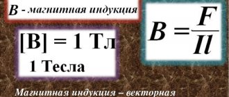
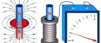
Magnetic induction is defined as the ability to influence an object using a magnetic field. This ability manifests itself when moving permanent magnet in the coil, as a result of which a current is induced (occurs) in the coil, while the magnetic flux in the coil also increases.
Tesla as a unit of measurement:
Tesla is a unit of measurement of magnetic flux density, magnetic field strength and induction in the International System of Units (SI), named after the inventor Nikola Tesla.
Tesla as a unit of measurement has a Russian designation - Tl and an international designation - T.
1 tesla is equal to the induction of such a uniform magnetic field in which a force of 1 newton acts on 1 meter of length of a straight conductor perpendicular to the magnetic induction vector with a current of 1 ampere. In other words, one tesla is equal to the field strength acting on a conductor with a force of one newton per meter of conductor at a current strength for each ampere of current.
Likewise, one tesla represents a magnetic flux density of one weber per square meter of area.
T = kg / (s2 A) = N / (A m) = Wb / m2.
1 T = 1 kg / (1 s2 · 1 A) = 1 N / (1 A · 1 m) = 1 Wb / 1 m2.
Tesla was introduced into the International System of Units by the decision of the XI General Conference on Weights and Measures in 1960, simultaneously with the adoption of the SI system as a whole. In accordance with the SI rules regarding derived units named after scientists, the name of the unit “tesla” is written with a lowercase letter, and its designation is written with a capital letter (T). This spelling of the designation is also preserved in the designations of derived units formed using an adze.
Physical meaning of magnetic induction
Physically, this phenomenon is explained as follows. The metal has a crystalline structure (the coil is made of metal). The crystal lattice of a metal contains electrical charges - electrons. If no magnetic influence is exerted on the metal, then the charges (electrons) are at rest and do not move anywhere.
Vasiliev Dmitry Petrovich
Professor of Electrical Engineering, St. Petersburg State Polytechnic University
If the metal comes under the influence of an alternating magnetic field (due to the movement of a permanent magnet inside the coil - namely movement), then the charges begin to move under the influence of this magnetic field.
As a result, an electric current arises in the metal. The strength of this current depends on the physical properties of the magnet and coil and the speed of movement of one relative to the other.
When a metal coil is placed in a magnetic field, the charged particles of the metal lattice (in the coil) are rotated at a certain angle and placed along the magnetic field lines.
The higher the strength of the magnetic field, the more particles rotate and the more uniform their arrangement will be.
Magnetic fields oriented in one direction do not neutralize each other, but add up, forming a single field.
Multiples and submultiples of tesla:
Multiples and submultiples are formed using standard SI prefixes.
| Multiples | Dolnye | ||||||
| magnitude | Name | designation | magnitude | Name | designation | ||
| 101 T | decatesla | yesTl | daT | 10−1 T | decitesla | dTl | dT |
| 102 T | hectotesla | gTl | hT | 10−2 T | centitesla | stl | cT |
| 103 T | kilotesla | kT | kT | 10−3 T | millitesla | mTl | mT |
| 106 T | megatesla | MTL | M.T. | 10−6 T | microtesla | µT | µT |
| 109 T | gigatesla | GTL | GT | 10−9 T | nanotesla | nTl | nT |
| 1012 T | teratesla | TTL | TT | 10−12 T | picotesla | pTl | pT |
| 1015 T | petatesla | PTl | P.T. | 10−15 T | femtotesla | ftl | fT |
| 1018 T | exatesla | ETL | ET | 10−18 T | attotesla | atl | aT |
| 1021 T | zettatesla | ZTL | ZT | 10−21 T | zeptotesla | ztl | zT |
| 1024 T | iottatesla | ITl | YT | 10−24 T | ioctotesla | iTl | yT |
Magnetic flux
Magnetic flux is a scalar quantity that characterizes the effect of magnetic induction on a certain metal circuit.
Magnetic induction is determined by the number of lines of force passing through 1 cm2 of the metal section.
The magnetometers used to measure it are called teslometers.
Abrahamyan Evgeniy PavlovichAssociate Professor, Department of Electrical Engineering, St. Petersburg State Polytechnic University The unit of measurement of magnetic induction in the SI system is Tesla (T).
After the movement of electrons in the coil ceases, the core, if it is made of soft iron, loses its magnetic qualities. If it is made of steel, then it has the ability to retain its magnetic properties for some time.
Magnet interaction
A permanent magnet (or magnetic needle) is oriented along the Earth's magnetic meridian. The end that points north is called the north pole (N), and the opposite end is called the south pole (S). Bringing two magnets closer to each other, we note that their like poles repel, and their opposite poles attract (Fig. 1).
If we separate the poles by cutting a permanent magnet into two parts, we will find that each of them will also have two poles, i.e., it will be a permanent magnet (Fig. 2). Both poles - north and south - are inseparable from each other and have equal rights.
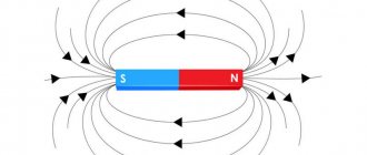
The magnetic field created by the Earth or permanent magnets is represented, like an electric field, by magnetic lines of force. A picture of the magnetic field lines of a magnet can be obtained by placing a sheet of paper over it, on which iron filings are sprinkled in an even layer. When exposed to a magnetic field, the sawdust becomes magnetized - each of them has north and south poles. The opposite poles tend to move closer to each other, but this is prevented by the friction of the sawdust on the paper. If you tap the paper with your finger, the friction will decrease and the filings will be attracted to each other, forming chains depicting magnetic field lines.
In Fig. Figure 3 shows the location of sawdust and small magnetic arrows in the field of a direct magnet, indicating the direction of the magnetic field lines. This direction is taken to be the direction of the north pole of the magnetic needle.
Basic formulas for calculating the MI vector
The magnetic induction vector, the formula of which is B = Fm/I*∆L, can be found using other mathematical calculations.
Law of Electromagnetic Induction
The law of electromagnetic induction (Faraday's law) sounds like this:
The induced emf in a closed loop is equal and opposite in sign to the rate of change of the magnetic flux through the surface bounded by the loop.
Mathematically it can be described by the formula:
| Faraday's law Ɛi — induced emf [V] ΔФ/Δt — rate of change of magnetic flux [Wb/s] |
The “–” sign in the formula allows you to take into account the direction of the induction current. The induced current in a closed circuit is always directed so that the magnetic flux of the field created by this current through the surface bounded by the circuit would reduce those changes in the field that caused the appearance of the induced current.
If the circuit consists of N turns (that is, it is a coil), then the induced emf will be calculated as follows.
| Faraday's law for a circuit of N turns Ɛi — induced emf [V] ΔФ/Δt — rate of change of magnetic flux [Wb/s] N - number of turns [-] |
The strength of the induction current in a closed conductive circuit with resistance R:
| Ohm's law for a conductive circuit Ɛi — induced emf [V] I - induction current strength [A] R - circuit resistance [Ohm] |
If a conductor of length l moves with speed v in a constant uniform magnetic field with induction B the emf of electromagnetic induction is equal to:
| Induction emf for a moving conductor Ɛi — induced emf [V] B—magnetic induction [T] v—conductor speed [m/s] l - conductor length [m] |
The occurrence of induced emf in a conductor moving in a magnetic field is explained by the action of the Lorentz force on free charges in moving conductors. The Lorentz force plays the role of an external force in this case.
A conductor moving in a magnetic field through which an induced current flows experiences magnetic braking. The total work done by the Lorentz force is zero.
The amount of heat in the circuit is released either due to the work of an external force, which maintains the speed of the conductor unchanged, or due to a decrease in the kinetic energy of the conductor.
A change in the magnetic flux penetrating a closed circuit can occur for two reasons:
- due to movement of the circuit or its parts in a time-constant magnetic field. This is the case when conductors, and with them free charge carriers, move in a magnetic field
- due to changes in time of the magnetic field with a stationary circuit. In this case, the occurrence of induced emf can no longer be explained by the action of the Lorentz force. The phenomenon of electromagnetic induction in stationary conductors, which occurs when the surrounding magnetic field changes, is also described by Faraday's formula
Thus, the phenomena of induction in moving and stationary conductors proceed in the same way, but the physical reason for the occurrence of induction current turns out to be different in these two cases:
- in the case of moving conductors, the induced emf is due to the Lorentz force
- in the case of stationary conductors, the induced emf is a consequence of the action on free charges of the vortex electric field that occurs when the magnetic field changes.
Biot-Savart-Laplace Law
Induction EMF formula
Describes the rules for finding B→ magnetic field, which creates a constant electric current. This is an experimentally established pattern. Biot and Savard identified it in practice in 1820, Laplace managed to formulate it. This law is fundamental in magnetostatics. During the practical experiment, a stationary wire with a small cross-section was considered, through which an electric current was passed. For study, a small section of wire was selected, which was characterized by the vector dl. Its module corresponded to the length of the section under consideration, and its direction coincided with the direction of the current.
Interesting. Laplace Pierre Simon proposed to consider even the movement of one electron as a current and, based on this statement, using this law, he proved the possibility of determining the magnetic field of an advancing point charge.
According to this physical rule, each segment dl of a conductor through which electric current I flows forms a magnetic field dB in the space around itself at an interval r and at an angle α:
dB = µ0 *I*dl*sin α /4*π*r2,
Where:
- dB – magnetic induction, T;
- µ0 = 4 π*10-7 – magnetic constant, H/m;
- I – current strength, A;
- dl – conductor section, m;
- r – distance to the point where the magnetic induction is located, m;
- α is the angle formed by r and the vector dl.
Important! According to the Biot-Savart-Laplace law, by summing the magnetic field vectors of individual sectors, it is possible to determine the MF of the desired current. It will be equal to the vector sum.
Biot-Savart-Laplace Law
There are formulas that describe this law for individual cases of MP:
- fields of direct movement of electrons;
- fields of circular motion of charged particles.
The formula for MP of the first type is:
B = µ* µ0*2*I/4*π*r.
For circular motion it looks like this:
B = µ*µ0*I/4*π*r.
In these formulas, µ is the magnetic permeability of the medium (relative).
The law under consideration follows from Maxwell's equations. Maxwell derived two equations for the magnetic field; the case where the electric field is constant is considered by Biot and Savart.
Superposition principle
For MF, there is a principle according to which the total vector of magnetic induction at a certain point is equal to the vector sum of all MI vectors created by different currents at a given point:
B→= B1→+ B2→+ B3→… + Bn→
Lenz's rule
To determine the direction of the induced current, you need to use Lenz's rule.
Academically, this rule is as follows: the induced current excited in a closed loop when the magnetic flux changes is always directed in such a way that the magnetic field it creates prevents the change in the magnetic flux causing the induced current.
Let's try a little simpler: the coil in this case is a dissatisfied granny. They take away her magnetic flux - she is unhappy and creates a magnetic field, which this magnetic flux wants to take back.
They give her a magnetic flux, take it, they say, use it, and she’s like, “Why did I give up your magnetic flux!” and creates a magnetic field, which expels this magnetic flux.
Characteristics of the magnetic field
Main characteristics:
- magnetic induction
- magnetic flux
- magnetic permeability
Magnetic induction (B)
This is the intensity of the magnetic field. The stronger a magnet or electromagnet creates a magnetic field, the greater the induction.
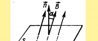
Formula: B = Ф / S.cos (