The author of the article is a professional tutor, author of textbooks for preparing for the Unified State Exam Igor Vyacheslavovich Yakovlev
Topics of the Unified State Examination codifier: the phenomenon of electromagnetic induction, magnetic flux, Faraday's law of electromagnetic induction, Lenz's rule.
Oersted's experiment showed that electric current creates a magnetic field in the surrounding space. Michael Faraday came to the idea that the opposite effect could also exist: the magnetic field, in turn, generates an electric current.
In other words, let there be a closed conductor in a magnetic field; Will an electric current arise in this conductor under the influence of a magnetic field?
After ten years of searching and experimentation, Faraday finally managed to discover this effect. In 1831 he carried out the following experiments.
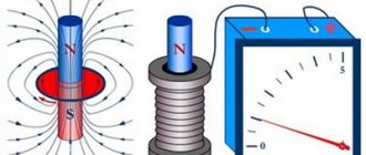
1. Two coils were wound on the same wooden base; the turns of the second coil were laid between the turns of the first and insulated. The terminals of the first coil were connected to a current source, the terminals of the second coil were connected to a galvanometer (a galvanometer is a sensitive device for measuring small currents). Thus, two circuits were obtained: “current source - first coil” and “second coil - galvanometer”.
There was no electrical contact between the circuits, only the magnetic field of the first coil penetrated the second coil.
When the circuit of the first coil was closed, the galvanometer registered a short and weak current pulse in the second coil.
When a constant current flowed through the first coil, no current was generated in the second coil.
When the circuit of the first coil was opened, a short and weak current pulse again arose in the second coil, but this time in the opposite direction compared to the current when the circuit was closed.
Conclusion
.
The time-varying magnetic field of the first coil generates (or, as they say, induces
) electric current in the second coil.
This current is called induced current
.
If the magnetic field of the first coil increases (at the moment the current increases when the circuit is closed), then the induced current in the second coil flows in one direction.
If the magnetic field of the first coil decreases (at the moment the current decreases when the circuit is opened), then the induced current in the second coil flows in a different direction.
If the magnetic field of the first coil does not change (direct current through it), then there is no induced current in the second coil.
Faraday called the discovered phenomenon electromagnetic induction
(i.e. “induction of electricity by magnetism”).
2. To confirm the guess that the induced current is generated by alternating
magnetic field, Faraday moved the coils relative to each other. The circuit of the first coil remained closed all the time, a direct current flowed through it, but due to movement (approach or distance), the second coil found itself in the alternating magnetic field of the first coil.
The galvanometer again recorded the current in the second coil. The induction current had one direction when the coils approached each other, and another direction when they moved away. In this case, the strength of the induction current was greater, the faster the coils moved.
.
3. The first coil was replaced by a permanent magnet. When a magnet was brought inside the second coil, an induction current arose. When the magnet was pulled out, the current appeared again, but in a different direction. And again, the faster the magnet moved, the greater the strength of the induction current.
These and subsequent experiments showed that an induced current in a conducting circuit occurs in all those cases when the “number of lines” of the magnetic field penetrating the circuit changes. The strength of the induction current turns out to be greater, the faster this number of lines changes. The direction of the current will be one when the number of lines through the circuit increases, and another when they decrease.
It is remarkable that for the magnitude of the current in a given circuit, only the rate of change in the number of lines is important. What exactly happens in this case does not matter - whether the field itself changes, penetrating the stationary contour, or whether the contour moves from an area with one density of lines to an area with another density.
This is the essence of the law of electromagnetic induction. But in order to write a formula and make calculations, you need to clearly formalize the vague concept of “the number of field lines through a contour.”
Magnetic flux
The concept of magnetic flux is precisely a characteristic of the number of magnetic field lines penetrating the circuit.
For simplicity, we restrict ourselves to the case of a uniform magnetic field. Let us consider a contour of an area located in a magnetic field with induction.
Let first the magnetic field be perpendicular to the plane of the circuit (Fig. 1).
Rice. 1.
In this case, the magnetic flux is determined very simply - as the product of the magnetic field induction and the area of the circuit:
(1)
Now consider the general case when the vector forms an angle with the normal to the contour plane (Fig. 2).
Rice. 2.
We see that now only the perpendicular component of the magnetic induction vector “flows” through the circuit (and the component that is parallel to the circuit does not “flow” through it). Therefore, according to formula (1), we have . But, therefore
(2)
This is the general definition of magnetic flux in the case of a uniform magnetic field. Note that if the vector is parallel to the plane of the loop (that is), then the magnetic flux becomes zero.
How to determine magnetic flux if the field is not uniform? Let's just point out the idea. The contour surface is divided into a very large number of very small areas, within which the field can be considered uniform. For each site, we calculate its own small magnetic flux using formula (2), and then we sum up all these magnetic fluxes.
The unit of magnetic flux is weber
(Wb). As we see,
Wb = T · m = V · s. (3)
Why does magnetic flux characterize the “number of lines” of the magnetic field penetrating the circuit? Very simple. The “number of lines” is determined by their density (and therefore their size - after all, the greater the induction, the denser the lines) and the “effective” area penetrated by the field (and this is nothing more than ). But the multipliers form the magnetic flux!
Now we can give a clearer definition of the phenomenon of electromagnetic induction discovered by Faraday.
Electromagnetic induction
- this is the phenomenon of the occurrence of electric current in a closed conducting circuit when the magnetic flux passing through the circuit changes
.
Impact on a flat circuit with current
Under such conditions, coefficient B is taken as a characteristic of the MF intensity at this location point and is called the MF induction. It is considered a quantity that combines the purpose of the MI vector with the direction of the magnetic field at this point in place.
An MF characterized in some areas by the same value of the MF vector is called a uniform MF. Induction in the international system (SI) is measured in units of Tesla (TL). The MI of a homogeneous MF is 1 t if it acts on a flat electron sequence with an area of 5 '= 1 m and a current of 7 = 1 A, located so that the magnetic lobes lie in the plane of the circuit p = 0.5 n sin p = 1 with a coefficient t = 1 Nm.
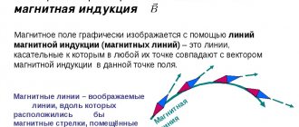
The area of location of any part that is associated with a specific vector is called a field. The concept of strings is widely used to visually represent VIs. In the case of a linear field, you can see a line, since the vector itself is oriented tangentially at any point. The tubular line is the area of the node, limited by the abundance of adjacent rows made through the closed outline. The vector field representation is often used to describe various body interactions. In particular, in the MP display, the background of the magnetic induction vector is mentioned, which defines the parts and tubes of the MP in it.
induced emf
What is the mechanism by which induced current occurs? We will discuss this later. So far, one thing is clear: when the magnetic flux passing through the circuit changes, some forces act on the free charges in the circuit - external forces
, causing the movement of charges.
As we know, the work of external forces to move a single positive charge around a circuit is called electromotive force (EMF): . In our case, when the magnetic flux through the circuit changes, the corresponding emf is called induced emf
and is designated .
So, induced emf is the work of external forces that arise when the magnetic flux through a circuit changes, moving a single positive charge around the circuit
.
We will soon find out the nature of the external forces arising in this case in the circuit.
Human body inductance
Our body is an electrical conductor, and all conductors, to one degree or another, have inductance. This means that we are exposed to an electromagnetic field; under its influence, alternating currents can be induced in our body.
The inductance of the human body is much less. than the inductance of an antenna or inductor, and small electromagnetic fields have practically no effect on us. But the higher the radiation power, and most importantly, the higher the frequency of the electromagnetic field, the stronger the impact. Strong microwave fields pose a mortal danger.
To protect people in industries associated with strong electromagnetic fields, special shielding clothing and shielded rooms are used. There are areas closed to visitors - around powerful antennas and radars.
From time to time, information appears about the dangers of long conversations on a mobile phone when the receiver is pressed to the head. The phone emits a high-frequency electromagnetic signal of low power, and due to the low power, its influence is negligible. But with prolonged exposure, this radiation can be harmful to health. It is preferable to use Skype installed on your computer.
Faraday's law of electromagnetic induction
The strength of the induction current in Faraday's experiments turned out to be greater, the faster the magnetic flux through the circuit changed.
If in a short time the change in magnetic flux is equal to , then the speed
changes in magnetic flux are a fraction (or, which is the same, the derivative of magnetic flux with respect to time).
Experiments have shown that the strength of the induction current is directly proportional to the magnitude of the rate of change of the magnetic flux:
The module is installed in order not to be associated with negative values for now (after all, when the magnetic flux decreases, it will be ). Subsequently we will remove this module.
From Ohm's law for a complete chain we at the same time have: . Therefore, the induced emf is directly proportional to the rate of change of the magnetic flux:
(4)
EMF is measured in volts. But the rate of change of magnetic flux is also measured in volts! Indeed, from (3) we see that Wb/s = V. Therefore, the units of measurement of both parts of proportionality (4) coincide, therefore the proportionality coefficient is a dimensionless quantity. In the SI system it is set equal to unity, and we get:
(5)
This is the law of electromagnetic induction
or
Faraday's law
. Let's give it a verbal formulation.
Faraday's law of electromagnetic induction
.
When the magnetic flux penetrating a circuit changes, an induced emf appears in this circuit equal to the modulus of the rate of change of the magnetic flux
.
Inductance and reactance
An inductor may offer negligible resistance to steady-state direct current, but its resistance to alternating current is significant. This resistance is called reactive.
Reactance converts the energy of electric current into the energy of an electromagnetic field. If an alternating voltage with frequency f is applied to a circuit with inductance L , then the reactance will be equal to
The higher the reactance, the lower the alternating current will be.
Reactance depends on frequency. Elements with small inductance create negligible resistance at low frequencies, but when moving from a frequency of 50 Hertz to a frequency of 50 MHz (megahertz), the resistance increases a million times.
At low frequencies, the inductance of small sections of wire is not taken into account, but at hundreds of megahertz and gigahertz, even the inductance of the wire leads of radio components must be taken into account. In ultrahigh-frequency technology, unframed elements that do not have wire leads are used. Instead, there are contact pads that are soldered onto a printed circuit board.
A circuit with inductive reactance, when supplied with alternating current, emits electromagnetic waves. But the reverse process is also possible: when exposed to an electromagnetic field, an alternating current is induced in the inductance.
Lenz's rule
We will call the magnetic flux, a change in which leads to the appearance of an induction current in the circuit, external magnetic flux
.
And we will call the magnetic field itself, which this magnetic flux creates, external magnetic field
.
Why do we need these terms? The fact is that the induction current arising in the circuit creates its own
a magnetic field that, according to the principle of superposition, is added to an external magnetic field.
Accordingly, along with the external magnetic flux, its own
magnetic flux created by the magnetic field of an induction current.
It turns out that these two magnetic fluxes - internal and external - are interconnected in a strictly defined way.
Lenz's rule
.
The induced current always has a direction such that its own magnetic flux prevents a change in the external magnetic flux
.
Lenz's rule allows you to find the direction of the induced current in any situation.
Let's look at some examples of applying Lenz's rule.
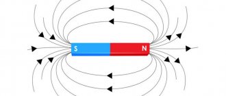
Let us assume that the circuit is penetrated by a magnetic field, which increases with time (Fig. (3)). For example, we bring a magnet closer to the contour from below, the north pole of which in this case is directed upward, towards the contour.
The magnetic flux through the circuit increases. The induced current will be in such a direction that the magnetic flux it creates prevents the increase in external magnetic flux. To do this, the magnetic field created by the induction current must be directed against
external magnetic field.
The induced current flows counterclockwise when viewed from the direction of the magnetic field it creates. In this case, the current will be directed clockwise when viewed from above, from the side of the external magnetic field, as shown in (Fig. (3)).
Rice. 3. Magnetic flux increases
Now suppose that the magnetic field penetrating the circuit decreases with time (Fig. 4). For example, we move the magnet downward from the loop, and the north pole of the magnet points toward the loop.
Rice. 4. Magnetic flux decreases
The magnetic flux through the circuit decreases. The induced current will have a direction such that its own magnetic flux supports the external magnetic flux, preventing it from decreasing. To do this, the magnetic field of the induction current must be directed in the same direction
, as the external magnetic field.
In this case, the induced current will flow counterclockwise when viewed from above, from the side of both magnetic fields.
Interaction of a magnet with a circuit
So, the approach or removal of a magnet leads to the appearance of an induced current in the circuit, the direction of which is determined by Lenz’s rule. But the magnetic field acts on the current! An Ampere force will appear acting on the circuit from the magnetic field. Where will this force be directed?
If you want to have a good understanding of Lenz's rule and the determination of the direction of the Ampere force, try answering this question yourself. This is not a very simple exercise and an excellent task for C1 on the Unified State Exam. Consider four possible cases.
1. We bring the magnet closer to the circuit, the north pole is directed towards the circuit. 2. We remove the magnet from the circuit, the north pole is directed towards the circuit. 3. We bring the magnet closer to the circuit, the south pole is directed towards the circuit. 4. We remove the magnet from the circuit, the south pole is directed towards the circuit.
Do not forget that the magnetic field is not uniform: the field lines diverge from the north pole and converge towards the south. This is very important for determining the resulting Ampere force. The result is as follows.
If you bring the magnet closer, the circuit is repelled from the magnet. If you remove the magnet, the circuit is attracted to the magnet. Thus, if the circuit is suspended on a thread, then it will always deviate in the direction of the movement of the magnet, as if following it. The location of the magnet poles does not matter in this case.
.
In any case, you should remember this fact - what if such a question comes up in part A1
This result can be explained from completely general considerations - using the law of conservation of energy.
Let's say we bring the magnet closer to the circuit. An induction current appears in the circuit. But to create a current, work must be done! Who does it? Ultimately, we are, moving the magnet. We perform positive mechanical work, which is converted into positive work of external forces arising in the circuit, creating an induced current.
So our work to move the magnet should be positive
.
This means that when we bring the magnet closer, we must overcome
the force of interaction between the magnet and the circuit, which, therefore, is a
repulsive
.
Now remove the magnet. Please repeat these arguments and make sure that an attractive force should arise between the magnet and the circuit.
Washing machine and inductive reactance
Users of automatic washing machines often complain that the current “breaks through to the drum.” The electrical insulation of such machines, as a rule, is in perfect order, but there is still an unpleasant sensation from touching the metal drum when loading and unloading things.
The reason is the induced current. The automatic machine has a power supply in which the mains voltage is converted into high-frequency. This high-frequency voltage is induced on all electrically conductive objects, in particular on the metal drum. The inductance of the drum is not standardized, but it is probably small. However, the high frequency current of the electronic circuit induces a response on the metal parts of the washing machine - a small current.
A similar phenomenon is sometimes observed by users of modern electronically controlled water heaters that heat tap water. If the power supply in the device is close to a water pipe, an alternating high-frequency current can be induced on it, and the water from the tap is “spiked.” You can avoid unpleasant sensations by disconnecting the electrical voltage from the boiler.
Faraday's Law + Lenz's Rule = Module Removal
Above we promised to remove the module in Faraday’s law (5). Lenz's rule allows us to do this. But first we will need to agree on the sign of the induced emf - after all, without the module on the right side of (5), the magnitude of the emf can be either positive or negative.
First of all, one of two possible directions for traversing the contour is fixed. This direction is declared positive
.
The opposite direction of traversing the contour is called negative
. Which direction of traversal we take as positive does not matter - it is only important to make this choice.
Magnetic flux through a loop is considered positive if the magnetic field penetrating the loop is directed in the direction from which the circuit is traversed in the positive direction counterclockwise. If, from the end of the magnetic induction vector, the positive direction of the round is seen clockwise, then the magnetic flux is considered negative.
Induction emf is considered positive if the induced current flows in a positive direction. In this case, the direction of external forces arising in the circuit when the magnetic flux through it changes coincides with the positive direction of bypassing the circuit.
On the contrary, induced emf is considered negative if the induced current flows in a negative direction. In this case, external forces will also act along the negative direction of the circuit bypass.
So, let the circuit be in a magnetic field. We fix the direction of the positive circuit bypass. Let's assume that the magnetic field is directed there, looking from where the positive detour is made counterclockwise. Then the magnetic flux is positive: .
Let us further assume that the magnetic flux increases. According to Lenz's rule, the induced current will flow in the negative direction (Fig. 5).
Rice. 5. Magnetic flux increases
Therefore, in this case we have . The sign of the induced emf turned out to be opposite to the sign of the rate of change of the magnetic flux. Let's check this in another situation.
Namely, let us now assume that the magnetic flux decreases. According to Lenz's rule, the induced current will flow in the positive direction. Therefore, (Fig. 6).
Rice. 6. Magnetic flux increases
This is, in fact, a general fact: given our agreement on the signs, Lenz’s rule always leads to the fact that the sign of the induced emf is opposite to the sign of the rate of change of the magnetic flux
:
(6)
Thus, the modulus sign in Faraday’s law of electromagnetic induction is eliminated.
Vortex electric field
Let us consider a stationary circuit located in an alternating magnetic field. What is the mechanism for the occurrence of induction current in the circuit? Namely, what forces cause the movement of free charges, what is the nature of these external forces?
Trying to answer these questions, the great English physicist Maxwell discovered a fundamental property of nature: a magnetic field changing over time generates an electric field
. It is this electric field that acts on free charges, causing an induced current.
The lines of the resulting electric field turn out to be closed, and therefore it was called a vortex electric field
. The vortex electric field lines go around the magnetic field lines and are directed as follows.
Let the magnetic field increase. If there is a conducting circuit in it, then the induced current will flow in accordance with Lenz’s rule - clockwise, if viewed from the end of the vector. This means that the force acting from the vortex electric field on the positive free charges of the circuit is also directed there; This means that the vector of the vortex electric field intensity is directed exactly there.
So, the lines of intensity of the vortex electric field are directed in this case clockwise (looking from the end of the vector , (Fig. 7).
Rice. 7. Vortex electric field with increasing magnetic field
On the contrary, if the magnetic field decreases, then the lines of intensity of the vortex electric field are directed counterclockwise (Fig. 8).
Rice. 8. Vortex electric field with decreasing magnetic field
Now we can better understand the phenomenon of electromagnetic induction. Its essence lies precisely in the fact that an alternating magnetic field generates a vortex electric field. This effect does not depend on whether a closed conducting circuit is present in the magnetic field or not; With the help of a circuit we only detect this phenomenon by observing the induced current.
The vortex electric field differs in some properties from the electric fields already known to us: the electrostatic field and the stationary field of charges that form a direct current.
1. The vortex field lines are closed, while the electrostatic and stationary field lines begin on positive charges and end on negative ones. 2. The vortex field is nonpotential: its work on moving a charge along a closed loop is not zero. Otherwise, the vortex field could not create an electric current! At the same time, as we know, electrostatic and stationary fields are potential.
So, induced emf in a stationary circuit is the work of a vortex electric field to move a unit positive charge around the circuit
.
Let, for example, the circuit be a ring of radius and penetrated by a uniform alternating magnetic field. Then the intensity of the vortex electric field is the same at all points of the ring. The work force with which the vortex field acts on the charge is equal to:
Therefore, for the induced emf we obtain:
Physical meaning of magnetic induction
Physically, this phenomenon is explained as follows. The metal has a crystalline structure (the coil is metal). The crystal lattice of a metal contains electrical charges - electrons. If there is no magnetic influence on the metal, the charges (electrons) are at rest and do not move anywhere.
Dmitry Petrovich VasilievProfessor of Electrical Engineering, St. Petersburg State Polytechnic University If a metal comes under the influence of an alternating magnetic field (due to the movement of a permanent magnet inside the coil - an exact displacement), then the charges begin to move under the influence of this magnetic field.
As a result, an electric current is generated in the metal. The strength of this current depends on the physical properties of the magnet and coil and the speed of movement of one relative to the other.
When a metal coil is placed in a magnetic field, the charged particles of the metal lattice (in the chestnut) are rotated through a certain angle and placed along the magnetic field lines.
The greater the magnetic field strength, the greater the number of particles rotating and the more uniform their arrangement will be.
Magnetic fields oriented in one direction do not neutralize each other, but add up to a single field.