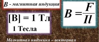
Magnetic induction is a force characteristic of a magnetic field at a selected point in space. It determines the force with which the magnetic field acts on a charged particle that moves inside it. Magnetic induction is considered a fundamental characteristic of a magnetic field (like strength for an electric field).
Magnetic induction describes the magnetic force (vector) on a test object (for example, a piece of iron) at each point in space. In simple words, if a natural magnet is brought near magnetic substances (such as iron, nickel, cobalt, etc.), it will induce magnetic properties in them, which is called “magnetic induction”. Magnetic induction is used to create artificial magnets.
Magnetic induction is also called magnetic flux density.
Magnetic induction is measured:
- in the SI system the unit is tesla (T),
- in the GHS system the unit is Gauss (Gs).
The relationship between T and G: 1 T = 10,000 G.
Magnetic induction is a vector quantity and is denoted by the letter B with an arrow:
Induction (from Latin inducere - introduce, induce) - the production of currents in a circuit under the influence of a magnet or other current.
Physical meaning of magnetic induction (MI)
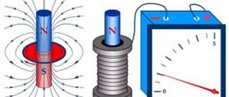
The ability to act on an object with a magnetic field (MF) determines the essence of true induction. It appears at the moment a magnet of a permanent nature moves in the inductance coil. The result of such movement is the appearance of current, with a simultaneous increase in magnetic flux. Since the winding of the coil is metal, and the metal structure is a crystal lattice, the physical properties of this phenomenon can be explained.
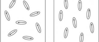
The electrons located in this lattice are at rest in the absence of magnetic influence. There is no movement. It begins at the moment when electrons come under the influence of an alternating magnetic field (the field changes when the permanent magnet moves).
The value of the current arising in the coil depends on the diameter of the core and the number of turns, the physical characteristics of the magnet and the speed of its movement.
The unit of dimension in the C system of the characteristic under consideration is tesla. It is designated by the letters Tl.
Important! The electrons in the lattice, after the coil enters the MP, turn at a certain angle and line up along the field lines of the MP. The number of oriented particles and the uniformity of their placement depend on the field strength.
Vector is the magnetic field induction vector (gradient parameter of the magnetic field).
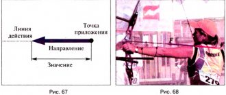
Magnetic induction vector
MI vector direction
The direction of magnetic fields can be indicated by a magnet arrow placed in these fields. It will spin until it stops. The northern end of the arrow will show where B→ the unit vector of a particular field is oriented.
Magnetic induction lines
The frame with current behaves in the same way, having the ability to navigate the MP without interference. The direction of the induction vector indicates the orientation of the normal to such a closed electromagnetic circuit.
Attention! The rule of the gimlet (right screw) is used here. If the screw is rotated in the direction of the current in the frame, then the forward movement of the screw will coincide with the direction of the positive normal.
In some cases, the right-hand rule is used to find direction.
Direction determination B→
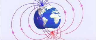
Visual display of MI lines
The line to which a tangent can be drawn, coinciding with B→, is called the magnetic induction (MI) line. Using such lines, you can visually display the magnetic field. These are closed contour lines that cover currents. Their density is always proportional to the value of B→ at a specific point in the MP.
Information. When dealing with the magnetic field of direct motion of charged particles, these lines are depicted as concentric circles. They have their center located in a straight line with the current, and are located in planes located at right angles to it.
The direction of magnetic lines can also be determined using the gimlet rule.
Graphic designation of MI lines
Magnetic induction vector module
Law of Electromagnetic Induction - Formula
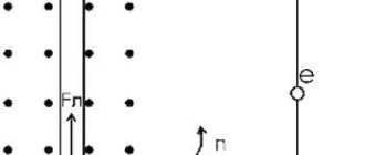
To determine the magnitude of the MI vector, you need to know its module. How is the magnitude of the magnetic induction vector (gradient) determined? This can be understood using a small model as an example. If you place a horizontally suspended conductor in the field of a horseshoe magnet, then the magnetic field of the magnet will act only on the area located in the interpolar gap. The force F→ acting on this section will be directed at right angles to the induction lines and the conductor itself. It reaches its maximum when the ort MI is located perpendicular to the conductor.
The value of the modulus B→ will be equal to the ratio of the maximum value of this force F → to the product of the length of the segment ∆ L by the force of movement of the charges ( I ), namely:
B = Fm/I*∆L.
Electrical model for determining module B→
For the curious
"Rotating" soup
If you ever take up cooking? for example, tomato puree soup, then try to swirl it thoroughly in the pan, and then take out the spoon. As you might expect, the soup will soon stop spinning, but you will notice that it will spin in the opposite direction for the last few seconds. Why is this happening? It turns out... The “strange” behavior of the soup can serve as an example of the occurrence of an elastic reaction in a viscous elastic liquid. When the rotation of the soup almost stops due to friction against the walls of the pan, its surface layer still continues to rotate. Then the surface layer, under the action of an elastic force acting between it and the rest of the soup, returns back, and the direction of rotation momentarily changes. After this, oscillations around the equilibrium position will continue for some time, unless the soup is so viscous that these oscillations will subside almost immediately.
And that is not all!
Basic formulas for calculating the MI vector
The magnetic induction vector, the formula of which is B = Fm/I*∆L, can be found using other mathematical calculations.
Biot-Savart-Laplace Law
Induction EMF formula
Describes the rules for finding B→ magnetic field, which creates a constant electric current. This is an experimentally established pattern. Biot and Savard identified it in practice in 1820, Laplace managed to formulate it. This law is fundamental in magnetostatics. During the practical experiment, a stationary wire with a small cross-section was considered, through which an electric current was passed. For study, a small section of wire was selected, which was characterized by the vector dl. Its module corresponded to the length of the section under consideration, and its direction coincided with the direction of the current.
Interesting. Laplace Pierre Simon proposed to consider even the movement of one electron as a current and, based on this statement, using this law, he proved the possibility of determining the magnetic field of an advancing point charge.
According to this physical rule, each segment dl of a conductor through which electric current I flows forms dB r and at an angle α :
dB = µ0 *I*dl*sin α /4*π*r2,
Where:
- dB – magnetic induction, T;
- µ0 = 4 π*10-7 – magnetic constant, H/m;
- I – current strength, A;
- dl – conductor section, m;
- r – distance to the point where the magnetic induction is located, m;
- α is the angle formed by r and the vector dl.
Important! According to the Biot-Savart-Laplace law, by summing the magnetic field vectors of individual sectors, it is possible to determine the MF of the desired current. It will be equal to the vector sum.
Biot-Savart-Laplace Law
There are formulas that describe this law for individual cases of MP:
- fields of direct movement of electrons;
- fields of circular motion of charged particles.
The formula for MP of the first type is:
B = µ* µ0*2*I/4*π*r.
For circular motion it looks like this:
B = µ*µ0*I/4*π*r.
In these formulas, µ is the magnetic permeability of the medium (relative).
The law under consideration follows from Maxwell's equations. Maxwell derived two equations for the magnetic field; the case where the electric field is constant is considered by Biot and Savart.
Superposition principle
For MF, there is a principle according to which the total vector of magnetic induction at a certain point is equal to the vector sum of all MI vectors created by different currents at a given point:
B→= B1→+ B2→+ B3→… + Bn→
Superposition principle
Circulation theorem
Initially, in 1826, Andre Ampère formulated this theorem. He analyzed the case with constant electric fields, his theorem is applicable to magnetostatics. The theorem states: the circulation of MF of direct electricity along any circuit is proportional to the sum of the forces of all currents that penetrate this circuit.
Worth knowing! Thirty-five years later, D. Maxwell generalized this statement, drawing parallels with hydrodynamics.
Another name for the theorem is Ampere’s law, which describes the circulation of MP.
Mathematically, the theorem is written as follows.
Mathematical formula of the circulation theorem
Where:
- B→– magnetic induction vector;
- j→ – electron motion density.
This is the integral form of writing the theorem. Here, on the left side one integrates along a certain closed contour, on the right side - along a stretched surface onto the resulting contour.
Magnetic flux
One of the physical quantities characterizing the level of magnetic field crossing any surface is magnetic flux. It is designated by the letter φ and has a unit of measurement called Weber (Wb). This unit is characteristic of the SI system. In the GHS, magnetic flux is measured in maxwells (Mks):
108 μs = 1 Wb.
Magnetic flux φ determines the magnitude of the magnetic field penetrating a certain surface. The flux φ depends on the angle at which the field penetrates the surface and the strength of the field.
The formula for calculation is:
φ = |B*S| = B*S*cosα,
Where:
- B is the scalar value of the magnetic induction gradient;
- S – area of the intersected surface;
- α is the angle formed by the flow Ф and the perpendicular to the surface (normal).
Attention! Flux Ф will be greatest when B→ coincides with the normal in direction (angle α = 00). Similar to Ф = 0, when it runs parallel to the normal (angle α = 900).
Magnetic flux
The magnetic induction vector, or magnetic induction, indicates the direction of the field. Using simple methods: the gimlet rule, a freely oriented magnetic needle or a circuit with a current in a magnetic field, you can determine the direction of action of this field.
Oersted's experience
However, it is not only permanent magnets that create a magnetic field.
In 1820, the Danish physicist Hans Christian Ørsted, at one of his lectures at the university, demonstrated to students an experiment in heating a wire from a “voltaic column”. One of the wires of the electrical circuit ended up on the glass cover of a marine compass lying on the table. When the scientist closed the electrical circuit and current flowed through the wire, the magnetic compass needle suddenly deviated to the side. Of course, Oersted initially thought it was just an accident. But, repeating the experiment under the same conditions, he got the same result. Then he began to change the distance from the wire to the arrow. The larger it was, the weaker the needle deviated. But that's not all. By passing current through wires made of different metals, he discovered that even those that were not magnetic suddenly became magnets when an electric current passed through them. The arrow deviated even when it was separated from the current-carrying wire by screens made of materials that did not conduct current: wood, glass, stones. Even when she was placed in a tank of water, she still continued to deviate. When the electrical circuit was broken, the magnetic compass needle returned to its original state. This meant that a conductor carrying an electric current creates a magnetic field
, causing the arrow to point in a certain direction.
Hans Christian Oersted
