One of the devices used to protect power lines with a voltage of 110 kV is directional current zero sequence protection (abbreviated as TNZNP).
These power lines are made with an effectively grounded neutral. Unlike 6-35 kV networks, in which the neutral is isolated, ground fault currents are quite large, which makes it necessary to record them and turn them off with the minimum possible time delay. But to do this, you need to not only determine the presence of a ground fault in the system, but also find the line on which it occurred. This is why such protections are made directional.
Zero sequence currents
A system of three-phase currents and voltages can be represented in the form of a vector diagram, where the vectors of these currents (voltages) in normal mode are shifted relative to each other in space by the same angle equal to 120 degrees . In this case, the resulting diagram is also rotating relative to the conditional observer: first the phase vector “A” passes by him, then “B”, then “C”. And so - in a circle. This diagram is usually called a positive sequence current (voltage) system.
If you change the order of the vectors from A-B-C to C-B-A, you get the reverse sequence. In both cases, one thing remains unchanged: an angle of 120 degrees is maintained between the vectors of different phases.
Zero sequence current or voltage is obtained if all these vectors are added together. To do this, if you remember the geometry, you need to combine the beginning of the second vector with the end of the first, then also add a third to it. Since the angle between them remains equal to 120 degrees, we get an equilateral triangle, the system is closed. The resulting vector, which determines the sum of all terms, will be equal to zero. It must be drawn from the beginning of the first summable vector to the end of the last.
But this will only happen if there are no ground faults in the system. With interphase current vectors increase simultaneously in two phases, or even in all three. Adding them together will give the same zero. Therefore, they are also called symmetrical.
Watch an interesting video about the work of TZNP below:
What is a zero break?
To fully answer this question, it is necessary to provide examples of the normal operation of a three-phase power supply input circuit. As an example, we will give a simplified version with an input for a floor distribution board.
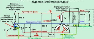
Scheme 1. Normal operation of the system
As can be seen from the figure, each of the apartments on the floor is powered from a separate phase (L1 - L3) and a common zero. Which forms a phase voltage of 220 volts (L1N=L2N=L3=220 V) in the household network of each apartment. In this case, a TN-CS power supply circuit is used, where a PE grounding bus is used, connected to the neutral in the building switchgear. The above system is balanced, since the load current in the phase wires is summed through the zero line, which reduces the likelihood of phase voltage imbalance.
Note that it is quite difficult to completely eliminate this phenomenon, since the load resistance at each phase may vary. For example, in apartment_1 the air conditioner and washing machine are turned on, in apartment_2 the owner turned on the boiler and electric stove, and in apartment_3 there are no residents and all household appliances are unplugged. As a result, voltage asymmetry will occur in a three-phase power system.
Now let's look at the network operation in abnormal mode, when the zero burns out.
Zero sequence current protection
But in the presence of a ground fault, the zero sequence of currents becomes unbalanced. A resulting current appears, to which the relay protection reacts.
In systems with an isolated neutral, a special transformer is used to separate these currents, which is placed on the cable.
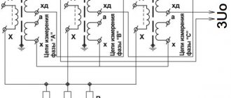
On a 110 kV power line, this cannot be done and ground fault currents are determined according to a different principle. For this purpose, on conventional current transformers used for relay protection, a separate winding is allocated for each phase. The windings of the phases are connected to each other in series in a special way: the beginning of the next one is connected to the end of the previous one. The current windings of the relay are also included in the same circuit.
Typically, the protected area is divided into sections (zones), approximately like distance protection. The protection itself is multi-stage. The operating current of the first stage is maximum, the time delay is minimum or equal to zero. The next stage operates at a lower current, but with a longer time delay. And so on.
The same protection is installed at the other end of the line. And there can be many lines. The presence of stages makes it possible to ensure the disconnection of the damaged area, as well as to reserve other protections in the event of their failure.
Causes of zero break
There are quite a few reasons - a break in the neutral at the substation, in house and access panels, inexperience of electricians, lack of maintenance of electrical networks, and so on. The main reason for neutral breakage is poor-quality wire fastening.
If the neutral is weakly fastened, the wire heats up, oxidizes (which increases the resistance of the neutral-to-housing transition) and burns out. It is also possible for the neutral to burn out when using large fuse ratings.
The neutral often breaks due to strong gusts of wind, icing, repair work, etc. As you can see, there are many reasons for the neutral to break. To avoid the consequences of this malfunction, you need to choose the right protection option.
Zero sequence voltage
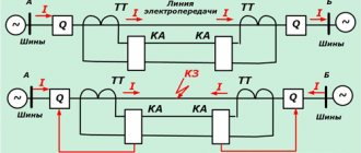
Having only information about zero-sequence currents, it is impossible to determine where the short circuit occurred: in the line itself, or “behind the back.” At the opposite end of the line there is either a switchgear with other power lines connected to it, or transformers. They have their own defense that will understand the situation better.
In order to determine the direction of a ground fault, information about the zero sequence voltage is required. It is taken from special windings of voltage transformers connected in an open triangle.
This is also a vector sum, but not of currents, but of phase voltages. It is equal to zero in normal mode and with symmetrical short circuits, but with single-phase short circuits it has a certain value.
Next, the power direction relay comes into play. One of its windings is supplied with a zero-sequence voltage, and the other is supplied with a current used to operate the ground protection. Triggering occurs at an angle between these values when the power is directed into the line. In other cases, when “behind the back”, the absence of operation of this relay blocks the operation of the protection.
Consequences of a zero break in a three-phase network
I'll tell you stories from my life.
- Electricians were repairing the entrance to the entrance. And during the repair, the working zero was turned off for a few seconds. A very unpleasant thing happened: when people returned home in the evening, they discovered that their TVs, refrigerators, chargers, etc. had burned out. - something that is constantly plugged into our outlets. It's good that there hasn't been a fire yet.
- Came on call, complained - tension was floating. I measure the voltage (everything is turned off) - almost 300 volts. Then, when the incandescent lamp is turned on, the voltage drops to 70V... It turned out that a bolt had burnt out in the floor panel, which received a zero. There was a break in the zero, a phase imbalance, and voltages went wild. I replaced the bolt, restored contact, and the voltage returned to normal.
Scratch bolt. Rusty, does not leak periodically. If you change it without turning it off, 100% of the equipment in the entrance will burn out!
An article on how I changed the electrical panel there is here.
I was called to an advertising and publishing company. According to preliminary estimates, the damage is more than 100 thousand rubles, and all due to poor contact on the zero bus:
Zero burnout from the zero bus
The neutral wire burned off from the second bolt. You can see how it fell off under tension. Before falling off, it ALMOST melted the insulation of the phase wires (vertical, red and white).
The server has not been turned on yet, perhaps the intellectual damage will be greater...
As you can see, such problems occur due to incorrect actions of “electricians” or due to spontaneous breakage (burnout) of the neutral wire in the old housing stock.
In this article I will tell you in detail why this happens and how to deal with it.
Unbalance currents
Correct addition of currents is only possible if the characteristics of the current transformers are completely identical. At the design stage, identical transformer windings with the same accuracy class and saturation factor must be selected for protection.
In addition, the circuits of these windings should not include other devices or instruments that violate the symmetry of their load.
But this may not be enough. If, despite all this, the magnetization characteristics turn out to be different, an unbalance current still appears. If in normal mode it does not lead to false operation of the protection, then with symmetrical short circuits, when the currents become several times larger, the unbalance current will increase significantly.
Therefore, when replacing current transformers, if it is not possible to find an analogue for one of them with full compliance with the current-voltage characteristics, then it is better to replace not one or two, but all three.
How it works
The principle of operation of the TZNP is to turn off the switching equipment in the event of single-phase faults with a certain time delay. The time delay is needed to organize selectivity of protection at different transformer substations.
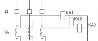
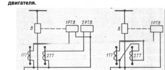
An example of a zero-sequence current protection circuit is shown in the figure below:
It uses a current relay KA and a power relay KW. To control the current in phases, current transformers (CTs) are used in TZNP. These are special instrument transformers that are placed on a bus or wire. An EMF proportional to the current flowing through the core or bus is induced on its windings.
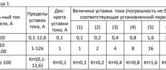
One of the main conditions for the correct operation of the TZNP is that the CTs have identical magnetization curves. This means that they must not only be identical in input and output characteristics, but also be of the same brand. In addition, it is worth noting that the errors in their output parameters should not be more than 10 percent. You can see them in the picture below.
To obtain the currents of the system taken out of balance, the signal is passed through a filter. In real applications, transformer windings are connected to each other. This is called a zero sequence current filter.
In the normal state of the electrical network, the zero-sequence currents are zero, and accordingly, the I outputs of the TZNP filter are also zero. In emergency mode, during a short circuit, the output current is different from zero. The remaining parts of the TZPN are configured in such a way as to exclude false alarms under a certain short-circuit current.
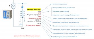
If previously zero-sequence current protection was in the form of relay circuits, now microprocessor terminals for protective circuits are being produced. That is, modern TZNP can be executed on microcontroller circuits.
The considered system is used as backup protection. Thanks to its properties, it is possible to achieve selectivity of operation, where the relay protection and protection of each subsequent TP operates faster than the previous one. Protection is needed to minimize further damage to power lines, transformers, generators, as well as to protect the environment and people who may enter the danger zone.
Finally, we recommend watching a useful video on the topic of the article:
Now you know what zero sequence current protection is, how it works and what it is needed for. If you have any questions, be sure to ask them in the comments below the article!
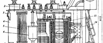
Implementation of TZNP protections
Protection panels for 110 kV power lines based on electromechanical relays, for example EPZ-1636, have been widely used since Soviet times. In addition to TZNP, it also includes distance protection and current cut-off.
However, electromechanical relays of panels in use have long expired, and their spot replacement does not always lead to reliable results.
Since progress has already gone far since the development of this relay technology, the old equipment is entirely replaced by panels or cabinets that include microprocessor relay protection terminals.