Some electrical circuits can be depicted as a simple circuit containing a power source and a small number of parts - resistors, capacitors, or others. But there are also large circuits that include several closed branches. In these cases, it is important to accurately calculate the electrical parameters at any given site. Kirchhoff's laws allow them to be determined by composing and solving several simple equations.
Kirchhoff's first law
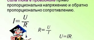
Ohm's law describes the relationship between voltage, resistance, and current in simple single-circuit circuits. In practice, complex branched circuits are more common, consisting of several circuits and many nodes, which cannot be described using standard rules for calculating series and parallel circuits.
Kirchhoff's rules, which in technical literature are usually called Kirchhoff's laws, allow us to determine the voltage and current in branched circuits. Although the name “rules” should be considered more correct, since they are not fundamental laws of nature. For example, Kirchhoff's first rule follows from the law of conservation of charge. It states that the sum of all currents in each node of an electrical circuit is zero.
The wording of the law requires clarification of the following terms:
- A node is a specific location on a circuit where 3 or more wires meet. Nodes can be called points located along one wire, if more wires are connected in these places.
- The movement of current directed to a certain node is conventionally called positive, the opposite - negative.
Kirchhoff's law, in simple words, can be formulated as follows: as many currents flow into a node, the same amount flows out. This indicates continuity of current for the electrical circuit. Therefore, there is another formula expressing Kirchhoff’s first rule:
Here, on one side of the equal sign, the currents entering a certain node are considered, and on the other, the currents leaving.
When using Kirchhoff's first law for an alternating current circuit, instantaneous voltage values are used, which are usually denoted by the letter İ. Calculations in this case are carried out using an equation presented in complex form.
Meaning in mathematics
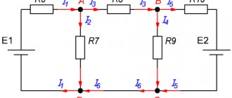
There is a circuit consisting of four circuits. The first contains a power source ε1 with internal source resistance r1, the second contains some kind of load R1. The third has a power source and load. The fourth consists of the load. Points B and F are nodes. The arrows next to them show the estimated direction of the current. An arrow inside the area shows the direction of the detour. It is necessary to find the current in the circuits: AK, AB, BF, CD. In theory, we need to create four equations, but since ε1 and R1 are the only ones in the KAB section, we will combine them into one chain. It turns out that you need to create three equations.
The first is taken from the first rule: I1 + I2 + I3 = 0. Since I1, I2 flow into node B, they have a positive sign, and I3 flows out of it, they have a negative sign. We substitute it into the equation and get I1 + I2 – I3 = 0, or in this form I1 + I2 = I3. We take the second and third equations from the second rule. To do this, we use the BCDFB contour and transform the formulation into a mathematical solution: ε2 = I2 × R2 + I3 × R3. For the ACDKA section we obtain, respectively, ε1 = I1 × R1 + I3 × R3. For clarity, we will display them separately.
I1 + I2 = I3
ε1 = I1 × R1 + I3 × R3
ε2 = I2 × R2 + I3 × R3
There were three tasks. Let's decide on the denominations. The first power supply is 6 V, the second is 12 V. Although this cannot be done, because the parallel power supplies must be the same, but this will be useful for us to learn an important lesson. The first resistance is 2 ohms, the second is 4 ohms, the third is 8 ohms.
It remains to insert the data into the equations and we get: for the second number 6 = 2I1 + 8I3, for the third number 12 = 4I2 + 8I3. Next we get rid of the common unknown I3. According to the first point, it is equal to I1 + I2. We substitute this sum instead and get: 6 = 2I1 + 8(I1 + I2), 12 = 4I2 + 8(I1 + I2). Open the brackets and add the same unknowns: 6 = 10I1 + 8I2; 12 = 12I2 + 8I1. To find I1, you need to get rid of I2. To do this, multiply the first equation by 12, and the second by 8 and get: 72 = 120I1 + 96I2; 96 = 96I2 + 64I1. We subtract the second from the first and write down the remainder -24 = 56I1, or I1 = -24/56 = -6/14 A. Why is the current negative?
Because the power sources are different. The voltage at the second source is higher than at the first, so the current flows in the opposite direction. We find I2, for this we insert the value of I1 into any of the last equations: 96 = 96I2 – 64 24/56. Divide the left and right parts by 96 and get: 1 = I2 – (64×24)/(96×56) or move the fractional part to the left, changing the sign. I2 = 1(64×24)/(96×56), after all reductions we get 1 4/14 A. To find I3, we use the first number: I3 = I1 + I2. I3 = -24/56 + 1 4/14 = 1(4×56)/(14×56) – (24×14)/(56×14) = 1,224/784 -336/784 = 1008/784 - 336/784 = 672/774 ≈ 0.87A. We got I1 = -6/14 A, I2 = 1 4/14 A, I3 ≈ 0.87 A.
Kirchhoff's second law
When we consider an electrical circuit connected to a current source, there is a certain potential at each point. The difference between them creates an electric field, which causes the charges to move.
A circuit is a closed circuit through which electrons move. The electric field does some work to move them. Each charge moves along the circuit, and then, under the influence of the source emf, closes the circle.
Kirchhoff's second law states that the work done to move a charge along any circuit circuit returning to the starting point is zero. This formulation implies any closed circuit, both one that includes a power source and one that does not.
The work of the electric field when moving a charge in the case under consideration is the sum of the voltage drops for each section of the circuit. Thus, the second rule or Kirchhoff's law states that the sum of the voltages of all branches in the circuit is equal to zero. This can be expressed as the following equation:
If the voltage and direction of circuit bypass coincide, then U is written with a plus sign, otherwise - with a minus sign. The direction of traversal of the selected contour can be determined arbitrarily. The second rule of Gustav Kirchhoff does not regulate it.
If there is one or more power supplies in the loop, then the formula can be expressed as follows:
There are p power sources, q circuit sections. The sum of all EMFs of available power supplies is equal to the sum of the voltage drops.
Kirghoff's second rule
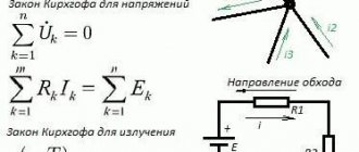
From Maxwell's third equation, Kirchhoff's rule for stresses follows. It is also called the second law.
This rule states that in a closed loop, on resistive elements, the algebraic sum of voltages (including internal ones) is equal to the sum of the emfs present in the same closed loop.
In this case, currents and EMF, the vectors of which coincide with the direction (selected arbitrarily) of bypassing the circuit, are considered positive, and currents counter to the bypass are considered negative.
Rice. 4. Illustration of Kirchhoff's second rule
The formulas shown in the figure are used in special cases to calculate the parameters of simple circuits.
Formulations of general equations:
, where where Lk and Ck are inductances and capacitances, respectively.
Linear equations are valid for both linear and nonlinear linearized circuits. They are used for any nature of temporary changes in currents and voltages, for different sources of EMF. Moreover, Kirchhoff's laws are also valid for magnetic circuits. This allows you to perform calculations to find the appropriate parameters.
The meaning of Kirchhoff's rules
Kirchhoff's laws express the fundamental principles of physics. Their formulations seem very simple and obvious. But in fact, they represent a method that allows you to calculate the electrical parameters of networks of very complex configurations.
Using Kirchhoff's laws, you can create a system of independent equations to calculate the parameters of an electrical circuit. It is important that their number is no less than the number of parameters that need to be determined.
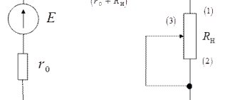
The figure below shows the electrical circuit for which the calculation will be carried out. Using the first law or Kirchhoff's rule, for node A we can write:
I = I1 + I2.
Two currents enter this node and one exits. Next, you need to apply the second rule. To do this, you can select the outer contour. It can be seen that there are two current sources and two resistors. Therefore, the following equations will be obtained:
Here are 2 equivalent formulas. The left side of the equation takes into account the electromotive forces of the two current sources, the right side takes into account the voltage drop across both resistors, taking into account the direction of the currents. Another equation can be obtained from the 2nd law when walking along the right inner contour:
The result is a system that includes three equations with three unknowns:
Using specific data, you can substitute numerical values into the system of equations and find what the current strength is for each branch belonging to node A. When making calculations, it is important to understand that with a fairly complex electrical circuit configuration, it is sometimes difficult to determine the direction of the current strength for each branch.
The first and second laws of Gustav Kirchhoff make it possible to accurately determine not only the magnitude of the current, but also its sign. If in the given example, after calculating the desired values using the presented system of equations, it turns out that the current with index 2 takes a negative value, then this means that in fact it has the direction opposite to that indicated in the figure.
Features of drawing up equations for calculating currents and voltages
First of all, the area to be explored is selected. Then an arrow is arbitrarily placed on each branch indicating the direction of current movement. This is necessary so as not to make mistakes later. When calculating, the directional inaccuracy will be corrected. Each arrow is designated by the letter I with an index. It will be more convenient to consider the section if the arrows are in close proximity to the point of connection of the circuits. Power supplies and resistors are also designated, and resistance is added to the common resistor.
Inside the area, the direction of the bypass is also randomly shown, focusing on possible potentials. It is necessary to compare the direction of current movement. This comparison will show which sign the number should have. If both directions coincide, put a + sign and a – sign if the directions are opposite.
The number of tasks assigned must correspond to the number of unknowns selected. Let's say there are three circuits and it is necessary to calculate their currents, which means that there should also be three formulas. It turns out that the new equation must have at least one new element that is not in the previous problems.
Laws for magnetic field
Kirchhoff's rules have also found their application in the calculation of magnetic circuits. Kirchhoff's first law for a magnetic circuit looks like this:
Simply put, the sum of all magnetic fluxes passing through a node is zero.
The second law, as applied to magnetic fields, is as follows: “The sum of the magnetomotive forces in a circuit is equal to the sum of the magnetic stresses.” The formula looks like this:
Kirchhoff derived rules that have an absolute applied nature. With their help you can solve practical problems in electrical engineering. The widespread use of these rules is explained by the simplicity of the formulation of the equations and the possibility of solving them using standard methods of linear algebra.
Implications for electrical engineering
Kirchhoff's rules are in addition to other laws. The main difficulty lies in finding areas, since their boundaries are not always easy to detect. After limiting the desired area, it is necessary to select all unknowns. Writing problems is already relatively easy. They are solved like ordinary equations.
Therefore, despite the first difficulties, these rules are still easier to compose and solve than using, say, Ohm's law. Therefore, they are widely used in electrical engineering. To understand how to apply the described method in practice, consider one example.
The validity of Kirchhoff's law on voltages regardless of the circuit topology
The fact that this circuit is parallel and not series has nothing to do with the validity of Kirchhoff's voltage law. In this respect, the circuit could be a "black box" (the configuration of its components is completely hidden from our view) with a set of exposed terminals between which we can measure the voltage - and Kirchhoff's voltage rule will still hold true:
Figure 8 – Validity of Kirchhoff’s law for voltages, regardless of the circuit topology
Try traversing the diagram above in any order, starting at any pin, and returning to the original pin, and you will find that the algebraic sum of the voltages is always zero.
Moreover, the "circuit" we trace for Kirchhoff's second law does not even have to be the actual path of current flow in the truest sense of the word. All we have to do to comply with Kirchhoff's voltage rule is to start and end at the same point in the circuit, counting the voltage and polarity drops as we move between points. Consider the following absurd example, following a 2-3-6-3-2 “loop” in the same parallel resistor circuit:
Figure 9 – Parallel circuit of resistors
Demonstration of Kirchhoff's voltage law in a series circuit
Let's look at our sequential circuit example again, this time numbering the points in the circuit to represent voltages:
Figure 1 – Demonstration of Kirchhoff’s voltage law in a series circuit
If we were to connect a voltmeter between points 2 and 1, the red test lead to point 2, and the black test lead to point 1, the voltmeter would register a reading of +45 volts. For positive readings on digital meter displays, the "+" sign is usually not shown, but rather is implied. However, for this tutorial, the polarity of the voltage readings is very important, so I will explicitly show the positive numbers:
E2-1 = +45 V
When voltage is indicated with a double subscript (the characters "2-1" in the notation "E2-1"), it means the voltage at the first point (2) measured relative to the second point (1). The voltage reported as "Ecd" will mean the voltage value shown by a digital multimeter with a red test lead at point "c" and a black test lead at point "d": the voltage at point "c" relative to point "d".
Figure 2 – Ecd value
If we were to take the same voltmeter and measure the voltage drop across each resistor, going around the circuit clockwise with the red test lead of our multimeter at the point in front and the black test lead at the point behind, we would get the following readings:
E3-2 = -10 V
E4-3 = -20 V
E1-4 = -15 V
Figure 3 – Determination of voltages in a series circuit
We should already be familiar with the principle common to series circuits that the individual voltage drops add up to the total applied voltage, but measuring the voltage drop in this way and paying attention to the polarity (mathematical sign) of the reading reveals another aspect of this principle: all measured voltages in the sum is equal to zero:
[begin{matrix} E_{2-1} = & +45 V &text{voltage at point 2 relative to point 1} \ E_{3-2} = & -10 V & text{voltage at point 3 relative to point 2} \ E_{4-3} = & -20 V & text{voltage at point 4 relative to point 3} \ E_{1-4} = & -15 V & text{voltage at point 1 relative to point 4} \ hline \ & 0 In end{matrix}]
In the example above, the outline is formed by the following points in the following order: 1-2-3-4-1. It doesn't matter where we start or what direction we go when following a contour; the sum of the stresses will still be zero. To demonstrate this, we can use the same circuit to calculate the voltages in the 3-2-1-4-3 circuit:
[begin{matrix} E_{2-3} = & +10 V &text{voltage at point 2 relative to point 3} \ E_{1-2} = & -45 V & text{voltage at point 1 relative to point 2} \ E_{4-1} = & +15 V & text{voltage at point 4 relative to point 1} \ E_{3-4} = & +20 V & text{voltage at point 3 relative to point 4} \ hline \ & 0 In end{matrix}]
This example can be clearer if we redraw our sequential diagram so that all components are represented on one straight line:
Figure 4 - Changing the representation of a daisy chain
This is still the same sequential circuit, only with slightly redistributed components. Note the polarity of the voltage drops across the resistors in relation to the battery voltage: the battery voltage is negative on the left and positive on the right, while all the voltage drops across the resistors are oriented in the other direction (positive on the left and negative on the right). This is because resistors resist the flow of electrical charge being pushed by the battery. In other words, the "pushing" applied by the resistors against the flow of electrical charge must be in the opposite direction to the source of the electromotive force.
Here we see what the digital voltmeter will show on each component in this circuit if the black wire is on the left and the red wire is on the right:
Figure 5 – Measuring voltages in a series circuit
If we were to take that same voltmeter and measure the voltage between combinations of components, starting with the single R1 on the left and working our way through the chain of components, we would see how the voltages add up algebraically (to zero):
Figure 6 – Measuring the sum of voltages in a series circuit
The fact that series voltages add up shouldn't be a secret, but we noticed that the polarity of these voltages makes a big difference in how these values add up. When measuring the voltage across R1 – R2 and R1 – R2 – R3 (I use the double dash symbol “–” to denote the series connection between resistors R1, R2 and R3), we see larger voltages being measured (albeit negative) , because the polarities of the individual voltage drops have the same orientation (plus on the left, minus on the right).
The sum of the voltage drops across R1, R2 and R3 is 45 volts, which is the same as the battery output voltage, except that the polarity of the battery voltage (negative left, positive right) is opposite the voltage drops across the resistors, so when measuring the voltage across the entire chain of components we get 0 volt.
The fact that we should get exactly 0 volts along the entire line should also not be a secret. Looking at the diagram, we see that the leftmost part of the line (left side of R1, point number 2) is directly connected to the rightmost part of the line (right side of the battery, point number 2), which is necessary to complete the circuit.
Since these two points are directly connected, they are electrically common to each other. Thus, the voltage between these two electrically common points must be zero.
Demonstration of Kirchhoff's voltage law in a parallel circuit
Kirchhoff's voltage rule (Kirchhoff's second law) will work for any circuit configuration at all, not just simple series circuits. Notice how this works for the following parallel circuit:
Figure 7 – Parallel circuit of resistors
In a parallel circuit, the voltage across each resistor is equal to the supply voltage: 6 volts. Summing up the voltages along the 2-3-4-5-6-7-2 circuit, we get:
[begin{matrix} E_{3-2} = & 0 V &text{voltage at point 3 relative to point 2} \ E_{4-3} = & 0 V & text{voltage at point 4 relative to point 3} \ E_{ 5-4} = & -6 V & text{voltage at point 5 relative to point 4} \ E_{6-5} = & 0 V & text{voltage at point 6 relative to point 5} \ E_{7-6} = & 0 V & text{voltage at point 7 relative to point 6} \ E_{2-7} = & +6 V & text{voltage at point 2 relative to point 7} \ hline \ E_{2-2} = & 0 V end{matrix}]
Please note that I designated the final (total) voltage as E2-2. Since we started our step-by-step path along the contour at point 2 and ended at point 2, the algebraic sum of these voltages will be the same as the voltage measured between the same point (E2-2), which of course must be zero.