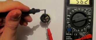
What is a capacitor?
A capacitor consists of two conducting plates located very close to each other and separated by a dielectric. Applying a constant voltage to the plates will cause current to flow and the appearance on both covers of charges equal in magnitude, but opposite in sign: negative on one and positive on the other. Disabling the power source will result in the charge not disappearing instantly, ignoring the phenomenon of its gradual leakage. Then, if the part covers are connected to some kind of load, for example, to a flash, the capacitor will discharge itself and return all the energy accumulated in it to the flash.
Capacitor designation
Capacitors are passive components that store electrical charge. This simple function is used in various cases:
- With alternating current.
- At constant current.
- In analog networks.
- In digital circuits.
Examples of using devices: synchronization systems, signal shaping, communications, filtering and signal smoothing, setting up televisions and radios.
Some notes and tips on working with capacitors
It must be remembered that capacitors with a higher rated voltage should be selected as the ambient temperature increases, creating a larger voltage reserve to ensure high reliability. If the maximum constant operating voltage of the capacitor is specified, this refers to the maximum temperature (unless otherwise stated). Therefore, capacitors always operate with a certain margin of safety. And yet, it is desirable to ensure that their actual operating voltage is at a level of 0.5-0.6 nominal.
If a limit value for alternating voltage is specified for a capacitor, then this applies to a frequency of (50-60) Hz. For higher frequencies or in the case of pulsed signals, the operating voltages should be further reduced to avoid overheating of the devices due to dielectric losses. High-capacity capacitors with low leakage currents are able to retain the accumulated charge for a long time after the equipment is turned off. To ensure faster discharge, for greater safety, you should connect a resistor with a resistance of 1 MOhm (0.5 W) in parallel with the capacitor.
Tags: sconce, view, engine, house, , capacity, sign, like, capacitor, design, circuit, , , power, multimeter, voltage, nominal, connection, potential, wire, start, , work, size, calculation, resistor, relay, row, connection, resistance, term, circuit, ten, type, current, three-phase, , filter, equivalent, effect
Capacitor Characteristics
The main characteristic of this element is capacitance, or C. It determines the ability of the device to collect electrical charge, depends on the geometric configuration of the covers and on the electrical constant of the dielectric between the covers.
Important! The capacitance depends on the type of dielectric used, as well as on the geometric dimensions of the element.
In order to describe the principle of operation of the device with a formula, it is necessary to understand that this is a constant proportionality in the equation, which represents the mutual dependence of the accumulated charge q on the area of the plates and on the potential difference V between them.
You may be interested in this Required indoor illumination
Power is expressed in units called farads F. But in practice smaller units such as microfarads and picofarads are also used.
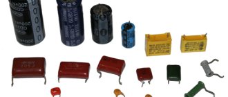
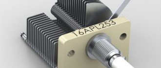
Appearance of devices
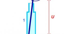
Thus, if a voltage U is applied to a capacitor, an electric charge accumulates on the caps of the part. The value of the accumulated charge on each plate is the same, they differ only in sign. This process of accumulation of electrical indicator is called charging.
Another parameter of the part is the rated voltage, namely, its maximum value that can be supplied to the capacitor. When a higher voltage is connected, dielectric breakdown occurs. This causes the element to short circuit. What the nominal voltage value will be depends on the type of dielectric and its thickness.
Important! The thicker the dielectric, the higher the rated voltage it can withstand.
Legend
Another parameter is the leakage current - the value of the conductive indicator that occurs when a constant voltage is applied to the ends of the element.
Addiction
Thanks to the description given earlier, we learned what capacity is. Next, we will try to figure out what this characteristic depends on. The capacitance of the capacitor depends on the distance between the plates, their area, as well as on the dielectric material itself. Thanks to this, we can say what the capacitance of the device depends on: it is directly proportional to the area of the capacitor plate and inversely proportional to the distance between the plates.
Let's consider how to find this value. For a flat capacitor, the formula for calculating capacitance is as follows:
The dependence of the device’s ability to accumulate charge on the area of its plates and the thickness of the dielectric layer also indicates that this value is also influenced by the overall dimensions of the element.
What are capacitors used for?
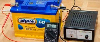
Power plants
Almost all electronic devices have a power supply that converts the alternating current present in the home into direct current. Capacitors play an important role in converting alternating current to direct current, eliminating electrical noise. Energy sources use electrolytic capacitors of various sizes, from a few millimeters to several inches (or centimeters).
Sound coverings
Capacitors have many uses in audio equipment. They block DC input to the amplifier, preventing sudden sounds or noise that could damage speakers and headphones. These parts are used in audio filters to control the bass.
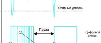
Computers
Digital circuits in computers transmit electronic pulses at high speeds. These network flows can interfere with signals from a nearby circuit, so high-tech equipment designers use capacitors to minimize interference.
High tech capacitor
How to correctly calculate the capacitance of a capacitor?
The simplest example of a capacitor is a flat model. It has the shape of two parallel covers made of a conductor, between which there is a dielectric layer. In order to know how to calculate the capacitance of capacitors, you need to apply the following formula:
You might be interested in this: Features of soldering
C = ex e0 xs / d,
where S is the surface area of the plates and d is the distance between them. In turn, this is the relative electrical permittivity of a given dielectric.
As a rule, capacitors are not used individually, but are connected to larger systems. They can be connected in series, parallel or mixed.
Capacity formula
Important! In series-connected elements, the absolute value of the charge on each plate is identical.
Thus, the resulting voltage is equal to the sum of these indicators on the individual components of the device.
The total capacity of the system will be determined by the formula:
1/С = 1/С1 + 1/С2 + 1/С3 + …
When connected in parallel, the potential difference on each part is the same. Thus, the total charge will be equal to the sum of the charges on the components of the capacitor, and the resulting capacitance will be equal to the sum of the individual unit values:
C = c1 + c2 + c3 + …
Variable capacitors
Capacitor energy
Initially, people had enough of the capacitors described above from a pair of plates. Then this device was developed. Devices in the form of balls, disks and cylinders began to appear. This was necessary in order to increase the capacitance of the capacitor C, because it is primarily related to the area of the plates S and the distance between them d. This is clearly seen from the formula. It is used to calculate the capacitance of the capacitor.
Capacitor capacity
Over time, these non-standard geometric shapes ceased to satisfy the needs of experimenters. Therefore, new devices with variable capacity were developed. They have movable plates. This allows you to easily change the area of their mutual intersection, thereby affecting the value of the capacitance of the capacitor. The most common and familiar example of this electronic device is the oscillatory circuit in the radio. All people have adjusted the receiver at least once. It is this “twist” that is a variable capacitor. When it rotates, the capacitance changes, and accordingly, the resonant frequency of the oscillatory circuit of the radio receiver changes. This in turn tunes the radio to a different station.
Appearance of a variable capacitor
Basic formulas for capacity
The basic calculation of a capacitor involves identifying the relationship between the capacitance and the charge held on the element, as well as the voltage on the plates.
C=QVC=QV
C – capacitance, or volume in Farads Q – charge held on the plates in coulombs V – potential difference between the plates in volts
This equation is used to calculate the work required to charge the capacitor and the energy stored in it.
Energy formula
W=∫Q0V dQW=∫0QV dQ
W=∫Q0qC dQW=∫0QqC dQ
W=12CV2
Important! It is necessary to know what effect a capacitor will have on any circuit in which it operates. It not only prevents the passage of the DC component of the signal current, but also affects any AC signal.
Reactance
In a DC circuit, in addition to the battery, there may be a resistor that resists the current in the circuit. The same is true for an alternating current circuit with a charge-storing element. A capacitor with a small plate area allows only a small amount of charge to be stored, and this will prevent current from flowing. A capacitor has a certain reactance, and it depends on its value, as well as on the operating frequency. The higher the frequency, the lower the reactance.
You may be interested in: Features of copper conductivity
The actual reactance can be calculated using the formula:
Xc = 1 / (2 pi f C)
Where
Xc – capacitive reactance in Ohms. f – frequency in Hertz. C is the capacitance in Farads.
Current calculation
The reactance of a capacitor, calculated using the above formula, is measured in Ohms. The current flowing in the circuit can then be calculated in the usual way using Ohm's law:
V = I Xc
Main capacitor indicator
Series-parallel (mixed) connection of capacitors
A series-parallel connection of capacitors is a circuit that includes sections with both parallel and series connections of capacitors.
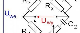
Figure 4 shows an example of a circuit section with a mixed connection of capacitors.
Figure 4. Series-parallel connection of capacitors.
When calculating the total capacitance of such a section of a circuit with a series-parallel connection of capacitors, this section is divided into the simplest sections, consisting only of groups with series or parallel connection of capacitors. Next, the calculation algorithm looks like:
1. Determine the equivalent capacitance of sections with series connection of capacitors.
2. If these sections contain series-connected capacitors, then first calculate their capacitance.
3. After calculating the equivalent capacitances of the capacitors, redraw the circuit. Typically, a circuit of equivalent capacitors connected in series is obtained.
4. Calculate the capacity of the resulting circuit.
One example of calculating capacitance for a mixed connection of capacitors is shown in Figure 5.
Figure 5. An example of calculating a series-parallel connection of capacitors.
More information about calculating the connection of capacitors can be found in the multimedia textbook on the basics of electrical engineering and electronics:
DID YOU LIKE THE ARTICLE? SHARE WITH YOUR FRIENDS ON SOCIAL NETWORKS!
Related materials:
- Electrical capacity
- Capacitor capacity
- Capacitor field energy
- Types of capacitors
- Capacitor designation
Comments
#20 Vladimir Nikolaevich 10/06/2019 09:48 In fact, if you connect 3 capacitors in series and each is 3 microfarads, and the voltage in the network is 100 volts, then the output will be 1 microforad and 300 volts. If in parallel, then the capacity will be 9 micro farads and the voltage will be 100 volts
Quote
#19 AlexeyDu 09/19/2019 07:03 In practice, as a rule, there is not exactly 110V at both ends, but approximately 120V at one end and 100V at the other, respectively, it is better to ground the end with the lower voltage and take it as zero. You can determine the end with less voltage using a simple indicator screwdriver with a tip with a closing thumb, i.e. the end that will glow with less brightness and must be taken as zero. If you cannot determine the difference in the indicator light, then you have an ideal generator and can ground either end of the outlet. I hope I helped you.
Quote
#18 AlexeyDu 09/19/2019 07:02 I quote Volodya:
I bought a gas generator, but the light blinks! and the stabilizer doesn't help. Maybe capacitors will help the problem? Thank you
If the gas generator is single-phase and has alternating voltage, then it operates on the principle of two half-cycles, i.e.
at each end (phase and zero) there is a voltage of 110V, respectively, in total they give 220V in the socket (with a frequency of 50 Hz, which you observe as a light bulb blinking). To get rid of the blinking effect, it is necessary to connect the generator housing and one end of the socket to a grounding circuit, then at the grounded end the voltage will become zero (0V), and at the other it will become equal to 220 (220V) of a pure sine wave and, accordingly, the grounded end will become zero, and unconnected phase. Quote #17 Denis25 10/09/2018 17:20 I quote Volodya:
I bought a gas generator, but the light blinks! and the stabilizer doesn't help. Maybe capacitors will help the problem? Thank you
Only an online type inverter will help.
Quote #16 Tram 03/26/2018 14:42 excellent article! Everything is straight forward, with clear examples. Thanks a lot)
Quote
#15 Topic 01/10/2017 18:23 What will be the total (equivalent) electrical capacitance if two 10F capacitors are connected in parallel in an electrical circuit: 5F? 10F? 15F? 20F?
Quote
#14 Ivan 07.25.2016 16:19 With a series connection, the capacitance of the capacitor does not increase, and in this case, 1+1+1=1 in series because the voltage supplied to this assembly increases!!!!
Quote
#13 Administrator 09.30.2015 15:05 I quote Humanoid:
Class. how much will it be if you connect three conducers in parallel at 1 μF = 3 μF, and how much will it be if you connect them in series 1/total=1/1+1/1+1/1=1+1+1= = 3 μF some kind of noodle
Interesting arithmetic, of course I apologize, but where is this taught?
Can I count, remembering third grade mathematics: 1/Tot = 1/1+1/1+1/1=1+1+1= = 3 that is, 1/Tot = 3 Now let’s express Tot = 1/3 = 0.3333333333 etc. In my opinion, it couldn’t be simpler. I think it is not electrical engineering that is to blame, but mathematics. So they came up with the idea of dividing... multiplying... So where are the noodles...? I’m sorry, I didn’t read the name. You’re a HUMANOID, then everything is clear! Quote #12 Humanoid 09.29.2015 22:44 Cool. how much will it be if you connect three conducers in parallel at 1 μF = 3 μF, and how much will it be if you connect them in series 1/total=1/1+1/1+1/1=1+1+1= = 3 μF some kind of noodle
Quote
#11 Andey 12/14/2014 11:32 Normal explanation
Quote
#10 Administrator 12/11/2014 19:59 Do I understand the alternator? If so, then the capacitors have nothing to do with it. The light bulb may blink due to the fact that you have not set the nominal engine speed, so the current frequency is less than 50 Hz, that is, it will be noticeable to the eye as blinking. I think we need to turn up the speed
Quote
Volodya 12/11/2014 19:02 I bought a gas generator, but the light is blinking! and the stabilizer doesn't help. Maybe capacitors will help the problem? Thank you
Quote
Larisa 04/02/2014 16:48 thank you!!! great, but they explained it!!!
Quote
Sergey 02/19/2014 07:20 The 3rd formula somehow doesn’t work well with the 2nd. The 2nd one turns out much more. Or am I confusing something?
Quote
Just Dmitry 02/11/2014 17:47 thank you for the information, this is exactly what I needed, otherwise there are no radio stores in my city, but I needed to get 400 from 470 microfarads, and in theory, using the formula, this is possible! author respect to you
Quote
Crater-2 12/12/2013 11:12 simply more intelligible than in institute textbooks
Quote
Vitalik 12/09/2013 18:16 but in my opinion all the formulas are the same except for the symbols themselves, like C1, like R1, and so on.
Quote
xXx 12/05/2013 07:05 if you think about it, it’s not that difficult
Quote
Power 04.12.2013 05:59 what a weak technician you have
Quote
Danilp 12/04/2013 05:35 Cool article, read it, understood it and got 10 in the technical department
Quote
Update list of comments
Active and reactive resistance
Although active and reactance are very similar. Even the values of both parameters are measured in Ohms, but they are not exactly the same. As a result, it is impossible to add them together directly. Instead, they need to be summed “vectorically”. In other words, you need to round each value and then add them together and take the square root of that number:
Xtot2 = Xc2 + R2
This article described in detail the main components, structure and operating principle of capacitors, and also provided basic formulas designed to calculate the useful volume of the device. For a deeper understanding, it is necessary to carefully consider the types of these parts and their practical features in various circuits and devices.
Units
The physical quantity determined by the ratio of the charge q of one of the capacitor plates to the voltage between the plates of the capacitor is called the electrical capacity of the capacitor:
With a constant arrangement of the plates, the electrical capacity of the capacitor is a constant value for any charge on the plates. The unit of electrical capacity in the international system is farad (F). An electrical capacitance of 1 F is possessed by a capacitor whose voltage between the plates is equal to 1 V when the plates are charged with 1 C of opposite charges. . In practice, submultiple units of electrical capacitance are widely used: microfarads (μF), nanofarads (nF) and picofarads (pF):
- 1 µF = 10-6F;
- 1 nF = 10-9F;
- 1 pF = 10-12F.
The electrical capacity of a capacitor is directly proportional to the area of the plates and inversely proportional to the distance between the plates. When a dielectric is introduced between the plates of a capacitor, its electrical capacity increases by e times. If two conductors isolated from each other are given charges q1 and q2, then a certain potential difference Δφ arises between them, depending on the magnitude of the charges and the geometry of the conductors.
The potential difference Δφ between two points in an electric field is often called voltage and denoted by the letter U. Of greatest practical interest is the case when the charges of the conductors are equal in magnitude and opposite in sign: q1 = – q2 = q. In this case, we can introduce the concept of electrical capacitance.
The electrical capacity of a system of two conductors is a physical quantity defined as the ratio of the charge q of one of the conductors to the potential difference Δφ between them. The value of electrical capacitance depends on the shape and size of the conductors and on the properties of the dielectric separating the conductors. There are configurations of conductors in which the electric field is concentrated (localized) only in a certain region of space.
Such systems are called capacitors, and the conductors that make up the capacitor are called plates. The simplest capacitor is a system of two flat conducting plates located parallel to each other at a small distance compared to the size of the plates and separated by a dielectric layer.
Such a capacitor is called a flat capacitor. The electric field of a parallel-plate capacitor is mainly localized between the plates (Figure 1); however, a relatively weak electric field also arises near the edges of the plates and in the surrounding space, which is called the stray field.
In a number of problems, one can approximately neglect the stray field and assume that the electric field of a flat capacitor is entirely concentrated between its plates (Figure 2). But in other problems, neglecting the stray field can lead to gross errors, since the potential nature of the electric field is violated.
It will be interesting➡ Direct current - definition and parameters
According to the principle of superposition, the field strength created by both plates is equal to the sum of the strengths and fields of each of the plates. Outside the plates, the vectors and are directed in different directions, and therefore E = 0. The surface charge density σ of the plates is equal to q/S, where q is the charge and S is the area of each plate. The potential difference Δφ between the plates in a uniform electric field is equal to Ed, where d is the distance between the plates. From these relations we can obtain a formula for the electrical capacitance of a flat capacitor:
Thus, the electrical capacity of a flat capacitor is directly proportional to the area of the plates (plates) and inversely proportional to the distance between them. If the space between the plates is filled with a dielectric, the electrical capacity of the capacitor increases by ε times. Examples of capacitors with different plate configurations include spherical and cylindrical capacitors.
Electrical capacity is a characteristic of a conductor, a quantitative measure of its ability to hold an electric charge. In an electrostatic field, all points on the surface of a conductor have the same potential.
The potential φ (counted from the zero level at infinity) is proportional to the charge q of the conductor, i.e. the ratio of q to φ does not depend on q. This allows us to introduce the concept of electrical capacity. From an isolated conductor, which is equal to the ratio of the charge of the conductor to the potential:
C = q/ φ
Thus, the greater the electrical capacity, the more charge a conductor can accumulate at a given φ. Electrical capacity is determined by the geometric dimensions of the conductor, its shape and the electrical properties of the environment (its dielectric constant) and does not depend on the material of the conductor. In particular, the electrical capacity of a conducting ball in a vacuum is equal to its radius. The presence of other bodies near a conductor changes its electrical capacity, since the potential of the conductor also depends on the electric fields created by charges induced in surrounding bodies due to electrostatic induction.
In the unit system SGSE electrical capacity is measured in centimeters, in SI - in farads: 1F = 9 * 1011 cm. The concept of electrical capacity also refers to a system of conductors, in particular two conductors separated by a thin layer of dielectric - an electrical capacitor. Electrical capacity of a capacitor (mutual capacitance of its plates)
С = q/ (φ1 – φ2),
where q is the charge of one of the plates (the charges of the plates are equal in absolute value), φ1 – φ2 is the potential difference between the plates. The electrical capacity of a capacitor is practically independent of the presence of surrounding bodies and can reach a very large value with small geometric dimensions of the capacitors.