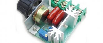
Powerful PWM regulator
Another electronic device with wide application. It is a powerful PWM (PWM) controller with smooth manual control. It operates at a constant voltage of 10-50V (it is better not to go beyond the range of 12-40V) and is suitable for regulating the power of various consumers (lamps, LEDs, motors, heaters) with a maximum current consumption of 40A. Sent in a standard padded envelope
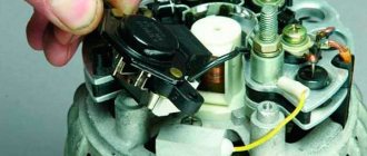
The case is held together with latches that break easily, so open it carefully.
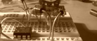
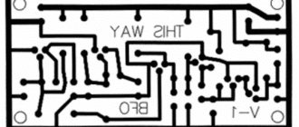
Inside the circuit board and the removed regulator knob
The printed circuit board is double-sided fiberglass, soldering and installation are neat. Connection via a powerful terminal block.
Ventilation slots in the case are ineffective, because... almost completely covered by the printed circuit board.
When assembled it looks something like this
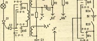
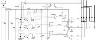
The actual dimensions are slightly larger than stated: 123x55x40mm Circuit diagram of the device
The declared PWM frequency is 12kHz. The actual frequency varies in the range of 12-13kHz when adjusting the output power. If necessary, the PWM operating frequency can be reduced by soldering the desired capacitor in parallel with C5 (initial capacitance 1nF). It is not advisable to increase the frequency, because switching losses will increase. The variable resistor has a built-in switch in the leftmost position that allows you to turn off the device. There is also a red LED on the board that lights up when the regulator is operating. For some reason, the markings on the PWM controller chip have been carefully erased, although it’s easy to guess that it’s an analogue of NE555. The control range is close to the stated 5-100%. Element CW1 looks like a current stabilizer in the diode housing, but I’m not sure exactly... As with most power regulators, regulation is carried out via the negative conductor. There is no short circuit protection. There are initially no markings on the mosfets and diode assembly; they are located on individual radiators with thermal paste. The regulator can operate on an inductive load, because At the output there is an assembly of protective Schottky diodes, which suppresses the self-induction EMF. A test with a current of 20A showed that the radiators heat up slightly and can draw more, presumably up to 30A. The measured total resistance of the open channels of field workers is only 0.002 Ohm (drops 0.04V at a current of 20A). If you reduce the PWM frequency, you will pull out all the declared 40A. Sorry I can't check...
You can draw your own conclusions, I liked the device
Simple PWM regulator
It is convenient to regulate the supply voltage of powerful consumers using regulators with pulse-width modulation. The advantage of such regulators is that the output transistor operates in switch mode, which means it has two states - open or closed. It is known that the greatest heating of the transistor occurs in a half-open state, which leads to the need to install it on a large area radiator and save it from overheating.
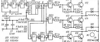
I propose a simple PWM regulator circuit. The device is powered from a 12V DC voltage source. With the specified instance of the transistor, it can withstand current up to 10A.
Let's consider the operation of the device: A multivibrator with an adjustable duty cycle is assembled on transistors VT1 and VT2. The pulse repetition rate is about 7 kHz. From the collector of transistor VT2, pulses are sent to key transistor VT3, which controls the load. The duty cycle is regulated by variable resistor R4. When the slider of this resistor is in the extreme left position, see the top diagram, the pulses at the output of the device are narrow, which indicates the minimum output power of the regulator. In the extreme right position, see the bottom diagram, the pulses are wide, the regulator operates at full power.
Diagram of PWM operation in KT1
Using this regulator, you can control 12 V household incandescent lamps, a DC motor with an insulated housing. If the regulator is used in a car, where the minus is connected to the body, the connection should be made through a pnp transistor, as shown in the figure. Details: Almost any low-frequency transistors can operate in the generator, for example KT315, KT3102. Key transistor IRF3205, IRF9530. We can replace the pnp P210 transistor with a KT825, and the load can be connected to a current of up to 20A!
Options for enabling a PWM regulator
And in conclusion, it should be said that this regulator has been working in my car with an interior heating engine for more than two years.
List of radioelements
| Designation | Type | Denomination | Quantity | Note | Shop | My notepad |
| VT1, VT2 | Bipolar transistor | KTC3198 | 2 | Search in the Otron store | To notepad | |
| VT3 | Field-effect transistor | N302AP | 1 | Search in the Otron store | To notepad | |
| C1 | Electrolytic capacitor | 220uF 16V | 1 | Search in the Otron store | To notepad | |
| C2, C3 | Capacitor | 4700 pF | 2 | Search in the Otron store | To notepad | |
| R1, R6 | Resistor | 4.7 kOhm | 2 | Search in the Otron store | To notepad | |
| R2 | Resistor | 2.2 kOhm | 1 | Search in the Otron store | To notepad | |
| R3 | Resistor | 27 kOhm | 1 | Search in the Otron store | To notepad | |
| R4 | Variable resistor | 150 kOhm | 1 | Search in the Otron store | To notepad | |
| R5 | Resistor | 1 kOhm | 1 | Search in the Otron store | To notepad | |
| R7 | Resistor | 100 Ohm | 1 | Search in the Otron store | To notepad | |
| Add all | ||||||
Attached files:
- PWM_regulator.rar (12 Kb)
Tags:
- PWM
- Sprint-Layout
PWM REGULATOR DIAGRAM
Adjusting the speed of electric motors in modern electronic technology is achieved not by changing the supply voltage, as was done before, but by supplying current pulses of different durations to the electric motor. PWM (pulse width modulated) regulators, which have recently become very popular, are used for these purposes. The circuit is universal - it also controls the engine speed, the brightness of the lamps, and the current in the charger.PWM regulator circuit
The above circuit works great, the printed circuit board is included.
Without altering the circuit, the voltage can be raised to 16 volts. Place the transistor depending on the load power.
You can assemble a PWM regulator using the following electrical circuit, with a conventional bipolar transistor:
And if necessary, instead of the composite transistor KT827, install a field-effect IRFZ44N, with resistor R1 - 47k. The polevik without a radiator does not heat up at a load of up to 7 amperes.
PWM controller operation
The timer on the NE555 chip monitors the voltage on capacitor C1, which is removed from the THR pin. As soon as it reaches the maximum, the internal transistor opens. Which shorts the DIS pin to ground. In this case, a logical zero appears at the OUT output. The capacitor begins to discharge through DIS and when the voltage on it becomes zero, the system will switch to the opposite state - at output 1, the transistor is closed. The capacitor begins to charge again and everything repeats again.
The charge of capacitor C1 follows the path: “R2->upper arm R1 ->D2”, and the discharge along the path: D1 -> lower arm R1 -> DIS. When we rotate the variable resistor R1, we change the ratio of the resistances of the upper and lower arms. Which, accordingly, changes the ratio of the pulse length to the pause. The frequency is set mainly by capacitor C1 and also depends slightly on the value of resistance R1. By changing the charge/discharge resistance ratio, we change the duty cycle. Resistor R3 ensures that the output is pulled to a high level - so there is an open-collector output. Which is not able to independently set a high level.
Recommendations for assembly and configuration
You can use any diodes, capacitors of approximately the same value as in the diagram. Deviations within one order of magnitude do not significantly affect the operation of the device. At 4.7 nanofarads set in C1, for example, the frequency drops to 18 kHz, but it is almost inaudible. If after assembling the circuit the key control transistor gets hot, then most likely it does not open completely. That is, there is a large voltage drop across the transistor (it is partially open) and current flows through it. As a result, a lot of power is dissipated for heating. It is advisable to parallel the circuit at the output with large capacitors, otherwise it will sing and be poorly regulated. To avoid whistling, select C1, the whistling often comes from it. In general, the scope of application is very wide; its use as a brightness regulator for high-power LED lamps, LED strips and spotlights will be especially promising, but more on that next time. This article was written with the support of ear, ur5rnp, stalker68. Forum on pulse width regulators
Forum for discussing the material PWM REGULATOR DIAGRAM
IN WHAT DIRECTION DOES THE CURRENT FLOW
In what direction does the current flow - from plus to minus or vice versa? An interesting theory about the essence of electricity.
We are converting a regular tractor toy into a radio-controlled one - photos of the process and the resulting result.
About the use of wireless power technology for various devices.SMD FUSES
Provides basic information about planar fuses, including their technical characteristics and applications.