To turn on electrical equipment, it is necessary to use a magnetic starter. However, when choosing it, you need to take into account its features. Correct model definition plays an important role in ensuring operational efficiency and trouble-free operation. In order for it to be optimally suited in a particular situation, you need to know how to make a choice in accordance with the existing requirements.
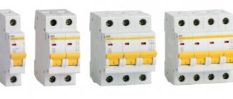
Different types of starters Source samelectrik.ru
Characteristics and types of starters by characteristics
Before choosing a contactor, you need to decide on the load, and make the choice based primarily on the load power. The parameters of contactors can be clarified on the manufacturers’ websites or from trading organizations, but here we will present and consider the most important ones. The main parameters (current, load power) are usually indicated on the starter housing.
Size (conditional dimensions) of the starter (contactor)
The most important parameter, the value characterizes the power and dimensions of the starter. There are the following starter sizes:
- zero value – for a maximum current of up to 6 A (through each working contact)
- the first - for a maximum current of up to 9 - 18 A (depending on the design of the contacts)
- starter 2 sizes – up to 25 – 32 A
- starter 3 sizes – up to 40 – 50 A
- starter 4 sizes – up to 65 – 95 A
- 5th size starter – up to 100 – 160 A
- sixth value – from 160 A and above
This means the current for application category AC-3 (for an inductive load), for category AC-1 (resistive or low-inductive load - for example, heating elements) the maximum current for the same starter will be one and a half to two times higher. The size of the starter determines how much power it can switch (three-phase circuit 380 V, inductive load).
- 1 – up to 2.2 – 7.5 kW
- 2 – up to 11 – 15 kW
- 3 – up to 18 – 22 kW
- 4 – up to 30 – 45 kW
It must be said right away that this power is really the maximum; you really need to look at the current value of a particular starter (usually the second and third digits in the name). The size of the starter is indicated in the name by the first digit. When the current is exceeded or the current is close to the maximum, the number of operations (reliability) decreases sharply, so the starter must be selected with a power reserve.
Number of contacts (poles)
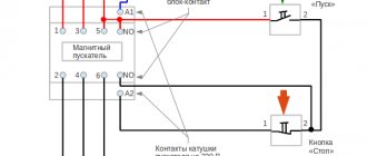
Contactors are mainly produced with three working contacts (for switching) and one additional one. An additional, or latching, contact is needed for interlocking, or “self-powering,” to lock the contactor in the on state when using the standard switching circuit. Additional contacts can be normally open (most often used) or normally closed.
To increase the number of additional contacts, contact attachments are used, the use of which significantly expands the range of circuit solutions. In the USSR, such additional consoles were called PKI, now there are other models on sale, but the essence is the same.
Additional contact attachments PKI, etc.
The maximum current of additional contacts, as a rule, is equal (in starters of the first and second values) or less than the maximum current of the main contacts. There are also additional contacts (attachments) of the PVL time delay, in which the contacts are turned on or off after a delay time. Read more in the article about pneumatic time delay relays.
Contactor coil voltage
Electromagnetic coils of contactors are usually available in the following voltages: 24, 36, 110, 230, 380 Volts. Larger starters use higher power coils. The coils are also sold separately, and it can be easily replaced in the contactor if a different voltage value is needed.
Contactor coils
As a rule, in the presence of a neutral conductor, it is advisable to use contactor coils for a voltage of 220 V, and in its absence (purely three-phase consumers) - coils for 380 V.
How to replace the contactor coil?
Sometimes a contactor with a coil of the required voltage is not available, so you don’t have to buy the entire contactor you need. Many manufacturers sell coils for different voltages and contactor sizes.
In particular, this applies to IEK, KEAZ. Foreign manufacturers, as a rule, make contactors non-separable, and do not sell coils for them separately.
It is worth saying that contactor coils for the required voltages should be included in repair kits, since this can be considered a consumable item. The main malfunctions of coils are winding breakage and housing deformation.
To increase the service life of contactor coils or electromagnets that remain on for a long time, it is permissible to operate them at a voltage of 85-90% of the nominal voltage.
Thermal and current relays
| No. | Type | Setting current, A | No. | Type | Setting current, A |
| 1. | RTT-111 | up to 25 | 14. | RTL 1010 | 3,6—6,0 |
| 2. | RTT-141 | 15. | RTL 1012 | 5,6—8,0 | |
| 3. | RTT-211 | up to 40 | 16. | RTL 1014 | 7,0—10,0 |
| 4. | RTT-311 | up to 100 | 17. | RTL 1016 | 9,5—14,0 |
| 5. | RTT-321 | up to 160 | 18. | RTL 1021 | 13,0—19,0 |
| 6. | RTL-1001 | 0,1—0,17 | 19. | RTL 1022 | 18,0—25,0 |
| 7. | RTL-1002 | 0,16—0,26 | 20. | RTL 2053 | 23,0—32,0 |
| 8. | RTL 1003 | 0,24—0,4 | 21. | RTL-2055 | 30—41 |
| 9. | RTL 1004 | 0,38—0,65 | 22. | RTL 2057 | 38,0—52,0 |
| 10. | RTL 1005 | 0,61—1,0 | 23. | RTL 2059 | 47,0—64,0 |
| 11. | RTL-1006 | 0,95—1,6 | 24. | RTL 2061 | 54,0—74,0 |
| 12. | RTL 1007 | 1,5—2,6 | 25. | RTL 2063 | 63,0—86,0 |
| 13. | RTL 1008 | 2,4—4,0 |
How does a circuit breaker work?
In the previous article we looked at the characteristics of circuit breakers, and now let's delve deeper. I…
Trigger parameters
For a variety of purposes, the following series of magnetic starters are produced: PA, PM, PMA, PME, PML. Based on the load parameters, the selection and use of these devices is carried out according to compliance.
PML series magnetic starter
1. The value of the electromagnetic starter is a conventional term that characterizes the permissible continuous currents of the contacts of the main power circuit. At the moment, there are the following numerical designations of quantities and the corresponding rated currents at a voltage of 380V in the AC-3 operating mode:
- “0” - 6.3 A;
- “1” – 10 A;
- “2” - 25 A;
- “3” - 40 A;
- “4” - 63 A;
- "5" - 100 A;
- “6” - 160 A;
- "7" - 250 A.
2. Operating mode of the starting device, which determines the nature of the switched load:
- AC-1, only active load, or low inductive load;
- AC-3, starting the electric motor and turning it off during rotation;
- AS-4, difficult starting of the engine, turning it off at low speeds and with a stationary rotor, countercurrent braking.
Magnetic starter sizes and categories of their application
3. Operating (switching) voltage of the relay coil, which can have the following values:
- Variable: 24; 36; 42; 110; 220; 380 V.
- Constant: 24V.
4.The number of additional contacts having this designation in Latin letters and Cyrillic letters:
- Normally open (NO), (NO);
- Normally closed (NC), (NC).
There are also special attachments that snap onto the starter housing, which additionally add several signal contacts.
PML series magnetic starter with snap-on attachment
5.Degree of protection of the device:
- IP00 - open, installed in heated rooms in closed electrical panels protected from foreign objects, water and dust;
- IP40 - manufactured in a housing, used inside unheated rooms where there is a small amount of dust in the air and water does not enter the device;
- IP54 - available in a housing, for indoor and outdoor use in places protected from precipitation and direct solar radiation.
6. The presence of a thermal relay that protects the connected circuits from prolonged overloads.
7. The presence of reverse, structurally implemented by combining in one housing two electromagnetic relays, each having three contact groups, with mechanical or electrical blocking of their simultaneous activation.
8. Wear resistance class, meaning the possible number of reliable switchings.
9.Additional controls.
Necessary parameter matching
Since the correct choice of an electromagnetic starter is the key to successful and uninterrupted operation of the connected electrical installations, it is necessary to comply with the above-described parameters of the characteristics of the switched circuit, control voltage, switching circuit, and type of environment. The most important rule is the requirement that the load current does not exceed the permissible contact current.
To connect an active load (without motors) of a certain power P, the strength of the flowing current I is determined from a simplified formula:
I=P/(√3*U) (A),
where U is the network voltage, 380 (V), .
According to the obtained value, select a starting device with a rated current not less than that calculated below in the table.
Magnetic starter selection table
Magnetic starters PMA series
· Rated currents: PMA-3000 - 40 A, PMA-4000 - 63 A, PMA-5000 - 100 A, PMA-6000 - 160 A.
· Coil voltage: 220—380 V; 50 Hz.
| No. | Type | Execution |
| 1. | PMA-3100 | Open, irreversible, without relay, 1P00 |
| 2. | PMA-3200 | Open, irreversible, with relay, 1P00 |
| 3. | PMA-3110 | Closed, irreversible, without relay, 1Р40 |
| 4. | PMA-3210 | Closed, irreversible, with relay, 1Р40 |
| 5. | PMA-3300 | Open, reversible, without relay, 1P00 |
| 6. | PMA-3400 | Open, reversible, with relay, 1P00 |
| 7. | PMA-3410 | Closed, reversible, with relay, 1Р40 |
| 8. | PMA-3500 | Open, reversible, without relay, 1P00 |
| 9. | PMA-4100 | Open, irreversible, without relay, 1P00 |
| 10. | PMA-4110 | Closed, irreversible, without relay, 1Р40 |
| 11. | PMA-4120 | Closed, irreversible, without relay, 1Р54 |
| 12. | PMA-4130 | Closed, irreversible, without relay, 1P40, with buttons |
| 13. | PMA-4140 | Closed, irreversible, without relay, 1P54, with buttons |
| 14. | PMA-4200 | Open, irreversible, with relay, 1P00 |
| 15. | PMA-4210 | Closed, irreversible, with relay, 1Р40 |
| 16. | PMA-4220 | Closed, irreversible, with relay, 1Р54 |
| 17. | PMA-4230 | Closed, irreversible, with relay, 1P40, with buttons |
| 18. | PMA-4240 | Closed, irreversible, with relay, 1P54, with buttons |
| 19. | PMA-4300 | Open, reversible, without relay, 1P00 |
| 20. | PMA-4310 | Closed, irreversible, without relay, 1Р40 |
| 21. | PMA-4320 | Closed, reversible, without relay, 1Р54 |
| 22. | PMA-4400 | Open, reversible, with relay, 1P00 |
| 23. | PMA-4410 | Closed, reversible, with relay, 1Р40 |
| 24. | PMA-4420 | Closed, reversible, with relay, 1Р54 |
| 25. | PMA-4500 | Open, reversible, without relay, 1P00 |
| 26. | PMA-4510 | Closed, reversible, without relay, 1Р40 |
| 27. | PMA-4520 | Closed, reversible, without relay, 1Р54 |
| 28. | PMA-4600 | Open, reversible, with relay, 1P00 |
| 29. | PMA-4610 | Closed, reversible, with relay, 1Р40 |
| 30. | PMA-4620 | Closed, reversible, with relay, 1Р54 |
| 31. | PMA-6102 | Open, non-reversible, without relay |
| 32. | PMA-6202 | Open, irreversible, with relay |
| 33. | PMA-6112 | Closed, irreversible, without relay, 1Р40 |
| 34. | PMA-6212 | Closed, irreversible, with relay, 1Р40 |
| 35. | PMA-6122 | Closed, irreversible, without relay, 1Р54 |
| 36. | PMA-6222 | Closed, irreversible, with relay, 1Р54 |
| 37. | PMA-6132 | Closed, irreversible, without relay, 1P40, with buttons |
| 38. | PMA-6232 | Closed, irreversible, with relay, 1P40, with buttons |
| 39. | PMA-6142 | Closed, irreversible, without relay, 1P54, with buttons |
| 40. | PMA-6242 | Closed, irreversible, with relay, 1P54, with buttons |
| 41. | PMA-6302 | Open, reversible, no relay |
| 42. | PMA-6402 | Open, reversible, with relay |
| 43. | PMA-6502 | Open, reversible, no relay |
| 44. | PMA-6602 | Open, reversible, with relay |
| 45. | PMA-6312 | Closed, reversible, without relay, 1Р40 |
| 46. | PMA-6412 | Closed, reversible, with relay, 1Р40 |
| 47. | PMA-6512 | Closed, reversible, without relay, 1Р40 |
| 48. | PMA-6612 | Closed, reversible, with relay, 1Р40 |
| 49. | PMA-6322 | Closed, reversible, without relay, 1Р54 |
| 50. | PMA-6422 | Closed, reversible, with relay, 1Р54 |
| 51. | PMA-6522 | Closed, reversible, without relay, 1Р54 |
| 52. | PMA-6622 | Closed, reversible, with relay, 1Р54 |
Safety precautions
Electric current has neither color nor smell. It cannot be seen or heard, but its presence is felt by touch or with the help of special devices. Touching a person can have negative consequences, so it is necessary to observe safety precautions when servicing the starter.
- Non-conductive parts must be grounded.
- Do not work under voltage.
- Observe safety precautions when turning off the voltage.
- Hang prohibited posters and, if necessary, install fences.
- Use additional protective elements (insulating gloves, boots, scissors, mats, safety glasses).
- During installation and repair, you must use proper tools.
Installation of the device
It is best to install the device on a hard, rigidly fixed surface in a vertical position. Incorrect installation often leads to false switching on and off of the device. A flat mounting surface is not so susceptible to strong shocks, vibrations and shocks.
The end of one conductor is bent into a ring when connected to the contact terminal of the device. If two conductors with the same cross-section are attached, then the ends are attached in a straight line on both sides of the clamping screw.
If you connect a copper wire, then the ends need to be tinned. Before connecting aluminum wires, the ends must be cleaned with a file. No lubrication of the device is allowed.
Before work, check the serviceability of the moving elements of the device and the correct connection of the electrical circuit.
If a thermal relay is additionally installed, then the device should not be mounted near thermal objects, so as not to expose it to unwanted load.
Characteristics of circuit breakers using the example of TEXENERGO
A few years ago, I published articles on my blog on choosing circuit breakers and why…
Folk way of choosing
To connect asynchronous electric motors with a squirrel-cage rotor, there is also a “folk” formula, according to which the rated current In of the motor is taken equal to twice the power value in kilowatts, that is, if
P = 3.7 kW, then Inom = 3.7 * 2 = 7.4 A.
Based on this value, a magnetic starter contactor is selected so that its rated operating current is not less than this value. In such calculations it is assumed that contactors with a suitable rated load value are able to withstand the start of electric motors with a multiple excess of starting currents Ip over the operating rated In, therefore the calculation of starting currents is not performed. A starter with a rated current of 10 A is suitable for this connection.
Criterias of choice
When choosing the required electrical device, its technical characteristics and design features are considered. Let's look at the main ones.
Rated voltage of the switched circuit . Most often, magnetic starters are used to start asynchronous motors with a squirrel cage rotor at an industrial voltage of 220/380 Volts. It is for this choice that most manufactured models of switching devices are designed. When using devices for 380/660 Volt electric motors, which are much less common, you must select a starter of the appropriate voltage.
Rated current of main contacts . Comparing the current of the connected load with the rated current of the switching device is one of the first actions when choosing the latter. Magnetic starters produced in the Russian Federation according to Soviet GOSTs, for example PML, are conventionally classified according to values corresponding to the rated current of the device. Below is a table of the ratios of values and rated currents. Using it, you can correctly select the magnetic starter by current or power by recalculating using the formula.
Electromagnetic contactors (starters)
We need to bring some order to the terminology. Starters and contactors are often confused. To some they are the same thing, and some say that a contactor is just a big, powerful starter. But no one can really explain how powerful it is...
Previously, during the Soviet era, this was the case. Now starters that were produced or developed in those days are called starters (for example, PML, which is still produced in Ukraine), and new and foreign models are called contactors.
Electricians call the same devices starters, and sellers call them contactors. To be honest, I’m more used to talking about starters.
How to choose the right electromagnetic starter?
An electromagnetic starter (contactor) is one of the most common devices for switching and controlling electrical loads. If you have motors and pumps, it is almost impossible to do without electromagnetic starters.
I have already written about the choice of electromagnetic starters. There I mainly looked at various schemes for constructing starters and how much it costs. With this note I would like to supplement and complete the topic of choosing electromagnetic starters.
Now I will tell you in more detail what factors you should pay attention to when choosing an electromagnetic starter or contactor.
1 We decide on the manufacturer.
For our purposes, PML, KMI, KTI starters are usually sufficient (I have never used them). From my own experience, I can say that about 90% of the starters used are for currents up to 25A, so somehow I didn’t have to work with KTI yet. If for some reason you cannot specify the manufacturer, you can list all the parameters. All electromagnetic starters are interchangeable.
2 Determine the rated current of the starter.
The rated current of the starter is the maximum current that an electromagnetic starter can pass through the contact group. Here there is a classification of starters up to 16A (first value), 25A (second value), 40A (third value), 63A (fourth value). There are also starters for high currents, but they are used very rarely in our projects. It should be borne in mind that the larger the starter, the larger its overall dimensions.
What is the difference between a contactor and a starter?
In fact, a contactor is a device consisting only of an electromagnetic coil and contacts. When voltage is applied to the coil, the contacts close (or open). The contactor does not contain devices for protection, fixation, switching, indication, etc. A starter is a device that contains a contactor as the main component element. In addition, the starter usually contains a thermal relay for protection against overcurrent, START and STOP buttons, an indication, can be enclosed in a housing, and have a circuit breaker for short-circuit protection. In other words, the starter is used to start (turn on) various electricity consumers.
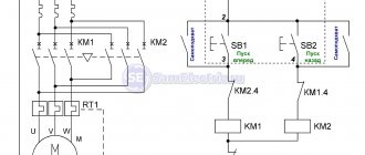
Details on how a three-phase electric motor is connected to a starter and various circuits for connecting an electric motor are given in my article on connecting asynchronous motors. And another example of using starters is in the article about the hydraulic press circuit. Various circuits for switching on magnetic starters.
And if you are at all interested in what I write about, subscribe to receive new articles and join the group on VK!
The starter can contain two contactors. This happens in cases where reverse engine control is used, or during a soft start, when a powerful engine is turned on first in a star circuit and then in a delta circuit.
Although such a scheme cannot be called “smooth”, there are special devices for smooth starting. Read my articles about the Soft Starter and about the Real Circuit for Switching on a Soft Starter.
Disassembled starter PML-1220 0*2B. The contactor and thermal relay are visible.
Principle of operation
The principle of operation of a magnetic starter is based on the phenomenon of electromagnetic induction. If no current passes through the coil, then there is no magnetic field in it. This causes the spring to mechanically push away the moving contacts. As soon as the power to the coil is restored, magnetic fluxes appear in it, compressing the spring and attracting the armature to the stationary part of the magnetic circuit.
Since the starter operates only under the influence of electromagnetic induction, the contacts open during power outages and when the network voltage drops by more than 60% of the nominal value. When the voltage is restored again, the contactor does not turn on on its own. To activate it, you will need to press the “Start” button.
If it is necessary to change the direction of rotation of an asynchronous motor, reversing devices are used. Reverse occurs thanks to 2 contactors, activated in turn. When the contactors are turned on simultaneously, a short circuit occurs. To eliminate such situations, the design includes a special lock.
Functionality
Magnetic starters find very wide application in various branches of economic activity and industry.
The most common areas of their use are the following:
- turning on street lighting, in-plant and yard lighting of industrial enterprises;
- switching of electric thermal heating elements and devices (heating elements and infrared emitters) in electric heating systems;
- control of electric asynchronous motors;
- use as main starters for industrial automation networks.
The question of choosing a magnetic starter arises when developing a particular electrical circuit that requires its use, as well as when performing scheduled or emergency repairs, when an analogue should be selected instead of a failed element.
Types of magnetic starters
Rated current and supply voltage of the control coil
Rated current is the most significant parameter, selected according to the consumer’s power. The main question: how to count correctly? When starting, any electric motor briefly produces power, often 5-7 times the rated power. Nevertheless, such a load remains for a fraction of a second and does not affect the operation of the release.
Based on this, we take into account only the rated power
To determine the denomination, it is necessary to calculate In. The formula from the physics textbook will help us with this: In = P/(U √3xcosφ), where P is power (W), U is voltage (V), and cosφ is the power factor of the engine.
For clarity, let's consider a specific example: suppose that you have a three-phase machine with a capacity of 5.5 kW with cosφ = 0.8 (this value is written in the electrical equipment passport). When turned on, the network will flow:
5500W / (380Vx√3×30.8)= 10.6A.
You still need to add 30% of the reserve to the resulting value, as a result, the optimal value will be 13A.
For example, if In is equal to 11.8A, in no case should you take a 12A model, otherwise it will burn out when the power increases.
The power supply to the control coil is selected according to two criteria: the type of electric current (AC or DC) and voltage (from 12V to 440V - DC, from 12V to 660V - AC at a frequency of 50 Hz and from 24V to 660V - AC at 60 Hz). There are also universal models with a coil operating on both AC and DC current.
Modular contactors
Intended for use for automatic control of consumers such as a small pump, fans, heating or lighting systems.
The series consists of a number of devices that differ in the number of working contacts, the switching power of the contacts and the value of the supply voltage of the excitation coil.
Version: stationary (DIN rail mounting).
Table 11.1. Modular contactors AC and ESB series
| Options | Unit | 230 AC | 400 AC | 400 AC | 400 AC |
| Rated current In, at AC-1 | A | 20 | 24 | 40 | 63 |
| Rated power at AC-1: | |||||
| · 230 V | kW | 1,3 | 2,2 | 5,5 | 8,5 |
| · 400 V | 4 | 6,5? | 11 | 15 | |
| Rated frequency | Hz | 50/60 | 50/60 | 50/60 | 50/60 |
| Control voltage | IN | 12, 24, 48, 110, 230 | 12, 24, 230 | 24, 230 | 24, 230 |
| Mechanical wear resistance (on/off) | Cycles (on/off) | 1000000 | 1000000 | 1000000 | 1000000 |
| Electrical durability (on/off): | Cycles (on/off) | ||||
| · at AC-1 | 150000 | 130000 | 150000 | 150000 | |
| · at AC-3 | 150000 | 500000 | 170000 | 240000 | |
| Power dissipation | W | 1 per pole | 1, 2 per pole | 3 | 6 |
| Number of modules | things | 1 | 2 | 3 | 3 |
Accessories
For modular contactors of the AC and ESB series, a contact attachment is available that has 1no+1no or 2no auxiliary contacts.
Rice. 5. Modular contactors
Mechanical and switching wear resistance
This characteristic shows the maximum number of on-off cycles - trips of the release. The more there are, the longer the service life will be.
This value is especially important for engines with frequent starts.
Mechanical wear resistance shows the number of on-off times in the absence of voltage. As a rule, the average mechanism can withstand about 10-20 million operations.
Electrical durability determines the permissible number of operation cycles and depends on the category of application. For example, if a contactor in AC-3 mode can withstand 1.7 million cycles, then in AC-4 it can withstand 200 thousand. As a rule, the manufacturer always indicates this characteristic in the technical data sheet.
Electrical wear resistance is divided into three classes:
- A - the highest, guarantees from 1.5 million to 4 million operations of the magnetic starter in operating mode;
- B - average, models of this class can withstand from 630 thousand to 1.5 million switchings;
- B - the lowest, the number of cycles from 100 thousand to 500 thousand.
Application categories
The first thing you need to pay attention to when choosing is the application categories - the tripping modes of the release. An electric motor is a complex mechanism with starting current and intermittent switching on, during which it does not operate in normal mode. In this case, the load on the network also differs from the nominal one, and the release mechanism must operate normally in non-standard conditions .
For alternating current, application categories are designated AC. They differ in the nature of operation:
- AC-1 - for electric motors with active or low-inductive loads;
- AC-2 - start with wound rotor, reverse braking;
- AC-3 - direct start of a squirrel-cage rotor, shutdown of rotating motors;
- AC-4 - starting and stopping electric motors with a squirrel-cage rotor by means of counter-connection. For this mode, paired (reversible) contactors with mechanical interlocking are used, which prevents the simultaneous start of several consumers. This reduces In and the base number of cycles.
For permanent, there are their own categories - DC:
- DC-1 (analogous to AC-1) - active or low-inductive load;
- DC-2 - start of electric motors with parallel excitation, shutdown at rated speed;
- DC-3 - start of motors with parallel excitation, shutdown when the rotor rotates slowly or when stationary;
- DC-4 - starting electric motors with sequential excitation and stopping at rated speed;
- DC-5 - starting motors with sequential excitation and stopping with a stationary or slowly rotating rotor, countercurrent braking.
Industrial electric motors with frequent starts must support category AC-3, AC-4 for alternating current, and DC-3, DC-4, DC-5 for constant current.
What's new in the VK SamElectric.ru group?
Contactor coil voltage
Electromagnetic coils of contactors are usually available in the following voltages: 24, 36, 110, 230, 380 Volts. Larger starters use higher power coils. The coils are also sold separately, and it can be easily replaced in the contactor if a different voltage value is needed.
As a rule, in the presence of a neutral conductor, it is advisable to use contactor coils for a voltage of 220 V, and in its absence (purely three-phase consumers) - coils for 380 V.
How to replace the contactor coil?
Sometimes a contactor with a coil of the required voltage is not available, so you don’t have to buy the entire contactor you need. Many manufacturers sell coils for different voltages and contactor sizes.
In particular, this applies to IEK, KEAZ. Foreign manufacturers, as a rule, make contactors non-separable, and do not sell coils for them separately.
It is worth saying that contactor coils for the required voltages should be included in repair kits, since this can be considered a consumable item. The main malfunctions of coils are winding breakage and housing deformation.
To increase the service life of contactor coils or electromagnets that remain on for a long time, it is permissible to operate them at a voltage of 85-90% of the nominal voltage.
Features of connecting PME-211 starters
Any contactor or magnetic starter, incl. PME211 should be used based on the characteristics for which it is designed. The main ones include control voltage and current. However, the requirements do not end there.
The operating conditions of the magnetic starter must meet the requirements of the “Rules for the technical operation of electrical installations by consumers.” Even the altitude above sea level is regulated. In normal mode, it should not exceed 2,000 m. At altitudes from 2 to 4.3 km, the operating current should be limited by 10%. In this case, the PME211 magnetic starter is mounted on a vertical surface with a maximum deviation from this position of no more than 90°. Its contact connectors must be clean and have a characteristic metallic sheen.
At the moment the magnetic starter is triggered, a mechanical impulse passes through its entire volume. This is caused by the “impact” of its contacts and the halves of the magnetic circuit. Therefore, such a device is subject to vibration. For this reason, it is advisable to connect flexible mounting wires in soft insulation to the magnetic starter. Rigid monolithic ones break off relatively quickly. The situation is further complicated by the fact that the location of such a break is usually hidden under insulation and is not visible visually.
Characteristics of devices
Magnetic starters produced by manufacturers differ from each other in purpose, the absence or presence of control buttons, thermal relays, degree of protection and other characteristics.
The most popular are the following series of devices:
- PML. This abbreviation indicates that the device is intended for motors with shorted rotors and furnaces with weak inductive loads.
- PMA. This starter is designed for asynchronous three-phase AC motors.
- PME. Reversible connection of asynchronous three-phase electric motors with squirrel-cage motors is carried out using models of this series.
- KMI. It operates in the same modes as PML, and also directly starts asynchronous motors when power is connected.
Based on the load current of the main contacts, an electromagnetic starter can be:
- First magnitude. Load current 10 A and 16 A.
- Second magnitude. With a load current of 25 A.
- Third value - 40 A.
- Fourth magnitude - 63 A.
The voltage of the control circuits must correspond to the operating voltage of the coil. It can be 24V, 220V, 380V.
The number of contacts in the control circuit is commensurate with the number of additional contacts of the starter. Breaking and closing contacts are counted separately.
Based on the degree of protection, the device is:
- dust and waterproof design;
- secure execution;
- open execution.
The first ones are used for outdoor installation. The latter are installed in unheated rooms with a minimum amount of dust, with no prerequisites for moisture ingress. Still others are installed in closed cabinets.
A model with a thermal relay is installed when the electric motor may experience overload due to its modes.
A reversible electromagnetic starter is used to regulate a reversible electric motor. Such a device contains six power contacts, two electromagnetic coils, and a mechanical interlock.
In terms of wear resistance, devices are produced in 3 classes:
- Class, A - the highest commutation wear resistance;
- Class B - average commutation wear resistance;
- Class B - low switching wear resistance.
On the model body, the manufacturer must indicate: the size of the starter, switched currents, operating voltage, load power, compliance with GOST or TU.
10.1. PKL contact attachment for PM12 starters
The PKL contact attachment is installed on a magnetic starter and serves to increase the number of its auxiliary contacts.
Specifications:
| Wear resistance level | B |
| Climatic performance | ABOUT |
| Accommodation category | 4 |
| Degree of protection | 1Р20 |
Table 10.1.1. Characteristics of the contact PCL attachment
| Set-top box type | Number of normally open contacts | Number of normally closed contacts | Dimensions, mm | Weight, kg |
| PKL 22M04B | 2 | 2 | 44 x 47 x 36 | 0,055 |
| PKL 20M04B | 2 | — | 25.5 x 47 x 36 | 0,03 |
| PKL 04M04B | — | 4 | 44 x 47 x 36 | 0,055 |
| PKL 40M04B | 4 | — | 44 x 47 x 36 | 0,055 |
| PKL 11M04B | 1 | 1 | 25.5 x 47 x 36 | 0,03 |
Differences between a relay and a contactor
Relays differ from contactors only in design and purpose, and the difference between them is sometimes barely distinguishable.
Usually,
- The relay does not have arc chutes.
- The relay is housed in a sealed housing.
- The relay is designed for low current and purely resistive loads.
- The relay has switching contacts, which means normally open and closed.
- The relay is not designed to connect a reactive three-phase load.
- A relay can have from 1 to 6 equivalent contacts, and a contactor must have 3 power and (as an option) 1-2 low-current contacts.
- The relay does not have additional functions or contacts, and the contactor can be supplemented with attachments for various installations and purposes.
- The relay is mounted on the panel and can be easily replaced using just your hands. In order to replace the contactor, you need to de-energize the equipment and use a screwdriver.
Contactors EH
Designed to control powerful consumers (current from 145 to 800 A).
Version: stationary (mounting on a circuit board).
Table 13.1. EH series motor contactors
| Type | Engine power, kW | Rated operating current, A | Number of cycles (millions) |
| EH 145 | 75 | 145 | 10 |
| EH 175 | 90 | 185 | 10 |
| EH 210 | 110 | 210 | 10 |
| EH 260 | 140 | 260 | 10 |
| EH 300 | 160 | 305 | 10 |
| EH 370 | 200 | 400 | 5 |
| EH 550 | 280 | 550 | 5 |
| EH 700 | 370 | 700 | 5 |
| EH 800 | 400 | 720 | 5 |
Rice. 11. EH series motor contactors
Table 13.2. Overload thermal relays
| Thermal relay | Contactors | Current setting range, A |
| T 200 DU | EH 145 EH 175 EH 210 | 80¸200 |
| T 450 DU | EH 175 EH 210 EH 260 EH 300 EH 370 | 130¸400 |
| T 900 DU | EH 370 EH 550 EH 700 EH 800 | 265¸850 |
Table 13.3. Time relay blocks (pneumatic)
| Contactor | Relay | Delay range |
| EH 175¸EH 800 | TP 40 D TP 180 D | with pneumatic attraction delay (blue handle) · 0.1¸40 s · 10¸180 s |
| TP 40 I TP 40 I | with pneumatic drop-off delay (black handle) · 0.1¸40 s · 10¸180 s |
Starter Maintenance
Like any equipment, this electrical device periodically requires maintenance. The minimum maintenance program includes:
- Visual inspection. Damage and chips may occur due to prolonged use of the device. Therefore, it is necessary to check the appearance of the starter for damage and the presence of all parts and components. It is necessary to remove dirt from the body and from the surface of the core.
- Cleaning contacts. If there are traces of melting or carbon deposits on the contacts, then you need to clean them with a needle file.
- Mechanical check. The spring is inspected, it should be rigid, the coils should be at a distance from each other. The absence of jamming of the armature stroke is checked, and if it is detected, the rubbing parts are lubricated or ground.
- Checking the coil. If there are cracks on the body, melted insulation or carbon deposits on the contacts, the coil must be replaced. A hum during operation of the device indicates an interturn short circuit. Over time, the active resistance of the coil decreases. In all these cases, it is better to rewind or replace it.
- Monitoring the absence of a short circuit. If the device in the housing has metal parts, you need to make sure that there is no short circuit between them.
- Checking the thermal relay. If a thermal relay is installed on the 220 V magnetic starter, it is necessary to check the adjustment settings of this relay. It is problematic to do this at home; special test benches are needed for this.
How the PME-211 magnetic starter works
To turn on a single-phase load of low power, toggle switches, buttons, switches are used, the contact system of which is mechanically driven and designed for small currents. To start and stop a three-phase load, an electrical device is required that would simultaneously supply voltage to all poles of electrical receivers, quickly disconnect from the supply network, extinguish the electric arc at high phase currents, etc. One of such devices is a magnetic starter, which is most often used for controlling asynchronous motors, electric heating units (heaters, electric boilers) and various low-power transformers, lighting networks and other electrical equipment. Let's look at how the magnetic starter of the PME-211 series is designed, activated and connected to the network.
Magnetic starter device
In addition to mechanical action, power contacts can be closed and opened using an electric drive. A fairly simple and common device is an electromagnet. Its most important ability is to attract metal objects when an electric current flows through its coil with a core, and to release it in the absence of current. Thus, an electromagnet has the ability to convert electrical energy into mechanical energy. If you combine a coil with a core, a movable attracting part with a return spring and power contacts in one housing, you will get a ready-made switching device. All electromagnetic relays, contactors and starters operate on this principle. Although their operating principle is the same, they are structurally different.
The collapsible body consists of three parts. The upper part of the cover closes the power contacts and extinguishes the electric arc during switching. Made from press material containing asbestos. In addition, the technical characteristics of the starter are indicated on the cover, such as series, rated voltage of the retractor coil, designation of power contact terminals, etc.
Fixed power and blocking contacts are fixed on the middle part, as well as movable ones on the traverse with an anchor.
And the third, the base, in which the retractor coil with the core is located. The collapsible body is cast from carbolite - phenol-formaldehyde resin with various mineral and organic fillers. This type of dielectric has high heat resistance and is difficult to ignite.
Let's take a closer look at all the elements of the PME-211 magnetic starter.
Magnetic core. The core and armature are made in the form of an W-shaped disconnected magnetic circuit. Like any other magnetic system for alternating current, it consists of sheets of electrical steel, insulated from each other to reduce eddy currents. To avoid shocks when turned on and strong vibrations during operation of the PME-211 magnetic starter, the contact points between the armature and the core are polished and smooth, and short-circuited turns made of non-magnetic material are additionally installed on the outer rods.
Power and blocking contacts are made in the form of rectangular plates of various shapes and thicknesses made of brass with soldering made of technical silver. The use of alloys with this precious metal is due to their resistance to electric arcs and mechanical shocks when turning the magnetic starter on and off. The content of technical silver in PME-211 is 10-11 grams.
on the retractor coils , and on magnetic starters of various brands the brand, wire diameter and number of turns are also written. The higher the voltage the coil is designed for, the higher the number of turns and the active resistance of its wire. If a voltage is applied to the coil above or below its rated value (380 V instead of 220 V and vice versa), this will lead to abnormal operation of the magnetic starter (loud crackling noise when the armature and core interact, failure of the magnetic starter to operate, etc.) and the coil will exit building.
In no case should the rated voltage be applied to the pull-in coil separately from the magnetic circuit, since in this case the magnetic flux will be closed on the turns of the coil, which will increase the current flowing through it and the coil will “burn out”.
A magnetic starter works on the following principle . When an alternating voltage is applied to the coil, an alternating electric current begins to flow in it, which, in turn, creates a magnetic flux in the core and armature, overcoming the resistance of the air gap. As a result, the magnetized armature is attracted to the core, closing the power and blocking contacts of the starter!
Technical characteristics of the magnetic starter PME-211-UHL4V
The main technical characteristics of the starter are given on the starter plate or on the top cover.
- alternating voltage of magnetic starter coil: 220 V, 380 V;
- rated voltage and current of the power circuit: at 380 V - 25 A, at 660 V - 14 A;
- rated power of the connected electric motor: no more than 11 kW;
- climatic modification UHL4 and wear resistance category B;
- fastening the case with screws;
- 2 normally open and 2 normally closed blocking contacts are installed.
Together with magnetic starters, thermal relays of the PTT brand of the appropriate size can be used to protect power equipment from prolonged overloads and from phase failure!
To change the rotation of the electric motor rotor, reversible magnetic starters are used, which are two starters of the same series, mounted on the same base, electrically connected, having electrical and mechanical interlocks that prevent the simultaneous activation of both starters.
On electrical circuit diagrams, magnetic starters are designated as follows:
Decoding magnetic starters
All used magnetic starters differ from each other in rated current, in the presence or absence of thermal relays (overload protection), in climatic design, overall dimensions and other parameters.
PME- X1 X2 X3 X4 X5, where
PME - magnetic starter series
X1 - rated current: 1 - 10A, 2 - 25A.
X2- version according to the degree of protection:
X3 – design of starters according to purpose and the presence of a thermal relay:
1-irreversible starter without thermal relay;
2-irreversible with thermal relay;
3-reversible without thermal relay;
4-reversible with thermal relay;
X4 – climatic version: U3, UHL4.
4 comments to the post “How the PME-211 magnetic starter works”
Interesting article about magnetic starters. Write an article on how to maintain magnetic starters!
The magnetic starter consists of two parts: the starter
and
contact block
.
Although the contact block
and is not the main part of a magnetic starter and is not always used, but if the starter operates in a circuit where additional contacts of this starter must be used, for example, reversing an electric motor, signaling the operation of the starter or turning on additional equipment by the starter, then for multiplication of contacts, just and serves as a contact block or, as it is also called,
a contact attachment
.
Switching principle
The closure of the contacts of the power circuit is carried out by a contactor - a device in which a group of contact plates coupled to the armature of an electromagnetic relay is closed to fixed contacts connected to the input and output terminals for connecting the supply voltage of the network and load lines.
Thus, with the help of low currents in the electromagnetic relay coil and low-current control signals, it is possible to switch high-current circuits of large loads. The small current and low voltage of the signal circuit makes the operator’s work much safer, and for automatic monitoring and control systems it gives a wide scope for their use, thanks to the introduction of computerized algorithms into the process.
This is interesting: At whose expense will electricity meters be replaced in 2022: let’s look into it thoroughly
Contactors and magnetic starters
Introduction
At the beginning of this article, I would like to immediately determine what the difference is between a contactor and a magnetic starter, since this question often baffles even the most experienced electrical specialists, while many believe that the difference between them lies in their design, overall dimensions or the value of the switched (rated) current, but this is not so. GOST 30011.4.1-96 will help us understand this issue, which provides the following definitions:
A contactor is a switching device with a single rest position, not manually operated, capable of switching on, carrying and breaking currents under normal circuit conditions, including during operating overloads.