Application of a magnetic starter
A magnetic starter (or contactor) is used to remotely switch on electrical equipment.
The advantage of a starter over simpler circuit closing devices (for example, a switch) is the separation of power and control circuits. This allows the starter to be placed in the power cabinet, and the controls to be placed in the work area. At the same time, control voltage and currents are minimal, which allows the use of wires of smaller cross-section. With increased safety requirements (high humidity in the room), it is enough to simply use a starter with a coil, for example, 24 V. The supply voltage of the electrical equipment can be 220 or 380 Volts.
In addition, the starter connection diagrams ensure safety in the event of a power failure in the network. In the event of a voltage failure, the power contacts open, and if voltage occurs, the starter will not supply voltage to the electrical equipment until it receives power through the start button.
An example from life. Some kind of lathe or milling machine is working. The tension is gone. The machine stopped. The worker started to adjust something in the working area of the machine, and then the tension appeared again. If the machine were controlled by a switch, the engine would immediately turn on, resulting in injury. When controlling the power supply using a magnetic starter, the machine will not turn on until the Start button is pressed.
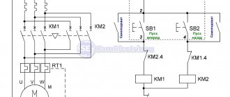
Below is a diagram of a simple starter switch to control the supply of voltage to electrical equipment. In our example, this is an asynchronous electric motor with a phase-to-phase supply voltage of 380 V. Accordingly, the voltage in one phase relative to zero is 220 V. The starter coil is designed for a voltage of 220 V.
In the initial position, we have voltage on power contacts 1, 2 and 3 of the starter, as well as on contact 1 of the “Start” button (normally open).
When you press the “Start” button, voltage is supplied to contact K2 of the starter coil through the normally closed contacts of the “Stop” button, closing the coil power circuit.
The coil creates a magnetic field, the core is attracted, closing the power contacts of the magnetic starter (1 and 4, 2 and 5, 3 and 6, respectively). In this position, voltage is supplied to the electric motor. At the same time, the NO block contact closes, the phase from which is supplied to the starter coil through the “Stop” button. Therefore, even when we release the "Start" button, the coil circuit remains closed, ensuring the closed position of the power contacts.
When the “Stop” button is pressed, the coil circuit is broken and the spring returns the power contacts to the initial (open) position. Accordingly, the voltage disappears from the wires supplying the electric motor, as well as from the NO block contact.
Characteristics and types of starters by characteristics
Before choosing a contactor, you need to decide on the load, and make the choice based primarily on the load power. The parameters of contactors can be clarified on the manufacturers’ websites or from trading organizations, but here we will present and consider the most important ones. The main parameters (current, load power) are usually indicated on the starter housing.
Size (conditional dimensions) of the starter (contactor)
The most important parameter, the value characterizes the power and dimensions of the starter. There are the following starter sizes:
- zero value – for a maximum current of up to 6 A (through each working contact)
- the first - for a maximum current of up to 9 - 18 A (depending on the design of the contacts)
- starter 2 sizes – up to 25 – 32 A
- starter 3 sizes – up to 40 – 50 A
- starter 4 sizes – up to 65 – 95 A
- 5th size starter – up to 100 – 160 A
- sixth value – from 160 A and above
This means the current for application category AC-3 (for an inductive load), for category AC-1 (resistive or low-inductive load - for example, heating elements) the maximum current for the same starter will be one and a half to two times higher. The size of the starter determines how much power it can switch (three-phase circuit 380 V, inductive load).
- 1 – up to 2.2 – 7.5 kW
- 2 – up to 11 – 15 kW
- 3 – up to 18 – 22 kW
- 4 – up to 30 – 45 kW
It must be said right away that this power is really the maximum; you really need to look at the current value of a particular starter (usually the second and third digits in the name). The size of the starter is indicated in the name by the first digit. When the current is exceeded or the current is close to the maximum, the number of operations (reliability) decreases sharply, so the starter must be selected with a power reserve.
Number of contacts (poles)
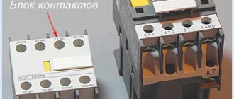
Contactors are mainly produced with three working contacts (for switching) and one additional one. An additional, or latching, contact is needed for interlocking, or “self-powering,” to lock the contactor in the on state when using the standard switching circuit. Additional contacts can be normally open (most often used) or normally closed.
To increase the number of additional contacts, contact attachments are used, the use of which significantly expands the range of circuit solutions. In the USSR, such additional consoles were called PKI, now there are other models on sale, but the essence is the same.
Additional contact attachments PKI, etc.
The maximum current of additional contacts, as a rule, is equal (in starters of the first and second values) or less than the maximum current of the main contacts. There are also additional contacts (attachments) of the PVL time delay, in which the contacts are turned on or off after a delay time. Read more in the article about pneumatic time delay relays.
Contactor coil voltage
Electromagnetic coils of contactors are usually available in the following voltages: 24, 36, 110, 230, 380 Volts. Larger starters use higher power coils. The coils are also sold separately, and it can be easily replaced in the contactor if a different voltage value is needed.
Contactor coils
As a rule, in the presence of a neutral conductor, it is advisable to use contactor coils for a voltage of 220 V, and in its absence (purely three-phase consumers) - coils for 380 V.
How to replace the contactor coil?
Sometimes a contactor with a coil of the required voltage is not available, so you don’t have to buy the entire contactor you need. Many manufacturers sell coils for different voltages and contactor sizes.
In particular, this applies to IEK, KEAZ. Foreign manufacturers, as a rule, make contactors non-separable, and do not sell coils for them separately.
It is worth saying that contactor coils for the required voltages should be included in repair kits, since this can be considered a consumable item. The main malfunctions of coils are winding breakage and housing deformation.
To increase the service life of contactor coils or electromagnets that remain on for a long time, it is permissible to operate them at a voltage of 85-90% of the nominal voltage.
Summary
Diagrams that depict the principle of connecting a relay to a contactor may have other letter or digital designations. Most often, their decoding is given below, but the principle always remains the same. You can practice a little by assembling the entire circuit with a consumer in the form of a light bulb or a small motor. Using the test key, you can work out a non-standard situation. The start and stop keys will allow you to check the functionality of the entire circuit. In this case, it is necessary to take into account the type of starter and the normal state of its contacts. If there are any doubts, then it is better to consult an electrician who has experience in assembling such circuits.
Electromagnetic contactors (starters)
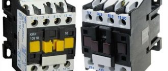
We need to bring some order to the terminology. Starters and contactors are often confused. To some they are the same thing, and some say that a contactor is just a big, powerful starter. But no one can really explain how powerful it is...
Previously, during the Soviet era, this was the case. Now starters that were produced or developed in those days are called starters (for example, PML, which is still produced in Ukraine), and new and foreign models are called contactors.
Electricians call the same devices starters, and sellers call them contactors. To be honest, I’m more used to talking about starters.
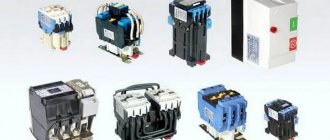
Device types
Starters for 380 V electric motors with squirrel-cage rotors allow you to remotely connect them to the network, reverse and stop them. The devices are:
- Open type. Installed in panels, closed boxes and places protected from dust.
- Closed execution. They are installed indoors, the control buttons are on the body.
- Dust-splash-proof. Suitable for indoor and outdoor installation, as they are protected from dust and moisture by a special visor.
- Relay. A magnetic starter with a thermal relay protects the motor in conditions of short overloads on the line. The relay switch is combined with the device or connected to it.
- Three-phase. A feature of a three-phase starter is that the starting current is not allowed to exceed the nominal value. If this is not the case, the device restores the phase and ensures uninterrupted operation of the engine at low starting currents.
Design versatility
According to their design, magnetic starters come with 3 and 4 poles, i.e. with 3-4 contacts. The fourth, in a normally open state, blocks the control circuit.
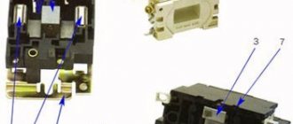
The electromagnetic mechanism is located inside and consists of a stationary W-shaped core and a coil with a winding. The moving unit is an anchor connected to a traverse and plastic. It contains contact bridges with active elements. Springs are used for smooth closure.
The fixed group of contacts is soldered onto plates with screw terminals. With their help you can connect a cable from an external line. Additional contacts are located on the sides of the device.
Some models have a special cover for the main contact group.
Electric starters with thermal relay
Magnetic starters with thermal relays allow you to protect the motor from short-term overloads. The installation current indicators can be set using a regulator - it is turned with a screwdriver. To prevent short circuits, models with thermal relays are not used.
The nuances of connecting EMF as part of the circuit
The classic EMF connection diagram is not particularly complex. In fact, if you do not take into account the auxiliary groups of contacts, three main lines are required to be connected - in a 380 volt circuit there are three phases.
In total there are 6 contacts - three input and three output, plus two contacts of the inductor circuit.
Electrical circuit for switching on the starter: A – input circuit (380 volts); B – output circuit (electric motor); 1 – magnetic starter; 2 – inductor power terminal; 3 – auxiliary contacts; 4 – grounding bus; 5, 6 – control buttons (+)
However, actual inclusion in an electrical circuit is often accompanied by a rather complex circuitry, where a large number of auxiliary contacts are involved.
As a rule, modern circuits for switching on the same electric motors require additional input of protection devices - thermal relays and others.
Assembling a switching device paired with a thermal relay. This connection option is used very often, as it provides additional protection for the load circuits and the load itself.
When connecting circuits to an EMF rated for 380V, you should adhere to the following rules:
- connect in complete absence of voltage;
- connect input circuits through a circuit breaker;
- use a wire cross-section that is optimally suited for the contact;
- tighten the screws until they stop, but without using excessive force;
- check the integrity of the coil winding (with an ohmmeter) before connecting the power line;
- check the overall movement of the moving chassis after all connections have been made.
As a rule, switching devices of this type are installed inside a cabinet designed for the installation of electrical lines. The cabinet design has a door for ease of maintenance and restricting access by unauthorized persons.
Why is everything so difficult
This question initially haunted me, but everything is complicated only at first glance. If you do all the work step by step, in accordance with the instructions, it will disappear by itself. As already mentioned, the main difficulties were created, one might say, intentionally. After all, all you had to do was purchase a more advanced push-button station at any electrical store, and most of the work simply lost its relevance. But the fact that I took such a problematic path also has its advantages - all options were considered at zero cost. Everything I needed was in the garage. But now I have the opportunity to use a low-cost sharpening machine. The only costs are the purchase of an emery grinding wheel and payment of electricity bills, which cannot be called large.
MP connection diagram
A popular scheme for connecting a magnetic starter via a push-button post.
The main circuit has two parts:
Our readers recommend!
To save on electricity bills, our readers recommend the Electricity Saving Box. Monthly payments will be 30-50% less than they were before using the saver. It removes the reactive component from the network, resulting in a reduction in load and, as a consequence, current consumption. Electrical appliances consume less electricity and costs are reduced.
- Three pairs of power contacts direct electrical power to electrical equipment.
- A graphical representation of the control, which consists of a coil, buttons and additional contactors that take part in the operation of the coil or prevent erroneous activation.
The most common wiring diagram is with one device. It's the easiest thing to deal with. To connect its main parts, you need to take a three-core cable and a pair of open contactors when the device is turned off.
Scheme with connecting a 220 volt coil
Will analyze a design with a voltage of 220 volts. If the voltage is 380 volts, you need to connect a different type of phase instead of the blue zero. In this situation, black or red. In case of blocking of the contactor, the fourth pair is taken, which works with 3 power pairs. They are located at the top, but the side ones are located on the side.
Pairs of power contactors are supplied with 3 phases A, B and C from the machine. To turn on when you touch the “Start” button, it is necessary that the voltage be equal to 220 V on the core, which will help the movable contactors connect with those that are stationary. The circuit will begin to close; to disconnect it, you need to disconnect the coil.
To assemble the control circuit, you need to connect one phase directly to the core, and connect the second phase using a wire to the start contact.
From the 2nd contactor we lay 1 more wire through the contacts to the other open contact of the “Start” button. A blue jumper is also made from it for the closed contactor of the “Stop” button; a zero from the electrical supply is connected to the 2nd contactor.
Working principle
The operating principle is simple. If you press the “Start” button, its contacts begin to close and a voltage of 220 volts flows to the core - it triggers the main and side contacts and an electromagnetic flux occurs. If the button is released, the contactors of the start button open, but the device is still turned on, since zero is transmitted to the coil through the closed blocking contacts.
In order to turn off the MP, you need to break the zero by opening the contacts of the “Stop” button. Again the device will not turn on, because the zero will be broken. To turn it on again, you will need to click “Start”.
How to connect a thermal relay?
You can also make a single-line graphic drawing of the connection of a three-phase electric motor to a magnetic starter via a relay.
Between the MP and an asynchronous electric motor, a relay is connected in series, which is selected depending on the specific type of motor. This device protects the motor from breakdowns and emergency conditions (for example, when one of the three phases disappears).
The relay is connected to the output from the MP to the electric motor, electricity passes through it in a series manner through the heating of the relay to the electric motor. On top of the relay there are additional contactors, which are combined with the coil.
Relay operation
Thermal relay heaters are designed for the maximum current that passes through them. When the current rises to unsafe limits for the motor, the heaters turn off the MP.
Installation of starters inside an electrical panel
The design of the MP allows installation in the middle of the electrical panel. But there are rules that apply to all devices. To ensure high reliability of operation, it is necessary that the installation be made on an almost straight and solid plane. Moreover, it is located vertically on the wall of the electrical panel. If there is a thermal relay in the design, then it is necessary that the temperature difference between the MP and the electric motor be as small as possible.
How to protect a contactor from overloads?
To protect industrial electric motors, together with a contactor, it is necessary to purchase and install a thermal relay.
Its main function is to open the main contacts when heated to extremely high temperatures. I advise you to select thermal relays and additional contacts from the official distributor - in the AxiomPlus online store. If you decide to buy, you can do it there. But the main thing is that this is the MOST sane (in my opinion) catalog with all the characteristics that can be selected, rather than flipping through printed catalogs.
Mandatory protection
Based on the fact that ultra-high temperatures will damage the working mechanism, and power connections may become soldered, such protection is mandatory. In this situation, an emergency stop of the engine will be required by de-energizing the circuit.
In addition, a thermal relay costs from 150 UAH, and such a purchase is completely justified. In essence, this is insurance for the future - it will increase the service life of the electromagnetic release and protect it from damage.
Combined and cheaper option
Popular manufacturers, for example IEK, have contactors (KMI series) equipped with thermal relays mounted inside the housing. If you purchase one of these analogues, you can save a lot, since the need to purchase additional protective devices is eliminated.
Alternative and universal solution
As an alternative, you can install one of these universal protection units (UBZ). It protects the network (and the motor) from:
- short circuits;
- power surges;
- violations of insulation resistance;
- technological overloads;
- climatic conditions - extreme temperatures, high humidity.
This system automatically measures and controls all operating parameters of the motor and prevents an emergency from occurring. UBZ includes the functions of a thermal relay and protects against a number of other negative factors.
The thermal relay and UBZ are selected according to the rated current and voltage. According to the design, they are mounted in a control panel or DIN rail.
Connecting the motor via starters
Irreversible magnetic starter
If it is not necessary to change the direction of rotation of the engine, then the control circuit uses two non-fixed spring-loaded buttons: one in the normal position is open - “Start”, the other is closed - “Stop”. As a rule, they are manufactured in a single dielectric housing, and one of them is red. Such buttons usually have two pairs of contact groups - one normally open, the other closed. Their type is determined during installation work visually or using a measuring device.
The control circuit wire is connected to the first terminal of the closed contacts of the Stop button. Two wires are connected to the second terminal of this button: one goes to any of the closest open contacts of the “Start” button, the second is connected to the control contact on the magnetic starter, which is open when the coil is turned off. This open contact is connected by a short wire to the controlled terminal of the coil.
The second wire from the “Start” button is connected directly to the terminal of the retractor coil. Thus, two wires must be connected to the controlled “pull-in” terminal – “direct” and “blocking”.
At the same time, the control contact closes and, thanks to the closed “Stop” button, the control action on the retractor coil is fixed. When the Start button is released, the magnetic starter remains closed. Opening the contacts of the “Stop” button causes the electromagnetic coil to be disconnected from the phase or neutral and the electric motor is turned off.
Reversing magnetic starter
To reverse the motor, two magnetic starters and three control buttons are required. Magnetic starters are installed next to each other. For greater clarity, let’s conditionally mark their supply terminals as 1–3–5, and those to which the motor is connected as 2–4–6.
For a reversible control circuit, the starters are connected as follows: terminals 1, 3 and 5 with the corresponding numbers of the adjacent starter. And the “output” contacts are crosswise: 2 from 6, 4 from 4, 6 from 2. The wire feeding the electric motor is connected to three terminals 2, 4, 6 of any starter.
With a cross connection scheme, simultaneous operation of both starters will result in a short circuit. Therefore, the conductor of the “blocking” circuit of each starter must first pass through the closed control contact of the adjacent one, and then through the open one of its own. Then turning on the second starter will cause the first one to turn off and vice versa.
Not two, but three wires are connected to the second terminal of the closed “Stop” button: two “blocking” and one supplying the “Start” button, connected in parallel to each other. With this connection scheme, the “Stop” button turns off any of the connected starters and stops the electric motor.
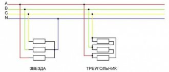
Starter capabilities
To limit the starting current of a three-phase motor, its windings can be connected in a star, then, if the motor has reached its rated speed, switch to a delta. In this case, magnetic starters can be: open and in a housing, reversible and non-reversible, with and without overload protection.
Each electromagnetic starter has blocking and power contacts. Power switches loads. Interlocking contacts are needed to control the operation of the contacts. Blocking and power contacts can be naturally open or normally closed. In circuit diagrams, contacts are shown in their normal state.
The ease of use of reversing starters cannot be reviewed. This includes operational control of three-phase asynchronous motors of various machines and pumps, and control of the ventilation system, fittings, right down to the locks and valves of the heating system. The possibility of remote control of starters is especially noteworthy if the electrical source of remote control switches the starter coils in a similar way to relays, and the latter safely connect power circuits.
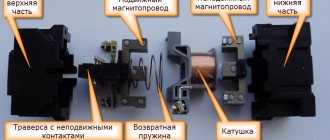
Magnetic starter design
The picture below shows the components of a typical starter. The stationary lower part, when the coil is connected to the power supply, forms an electromagnetic field that attracts the moving element. The contacts connected to the armature close the operating circuit. If the winding is de-energized, the spring will return the system to its original state.
Main functional elements of the starter
The core of the electromagnet is assembled from plates in the shape of the letter “W”. A large number of components block parasitic currents (skin effect). The number of turns is selected taking into account the supply voltage.
Sectors with designations
Explanatory inscriptions on the body are divided into three groups:
- general information and scope (AS1-4);
- information about permissible currents in load circuits (conversion to kW or reverse is performed taking into account the mains voltage);
- graphic designation of contact groups (the broken line indicates synchronous switching).
Each area can be explored in detail. To familiarize yourself with the classification by purpose categories, follow the standards of GOST R 50030.4.1.-2002. The designation AC1 indicates the possibility of connecting the starter to heating elements, incandescent lamps and other loads with weakly expressed reactive characteristics. If you need to ensure the start of a powerful engine, choose a model of the AC3 category.
Contact attachment
This part is mounted on a 220V electromagnetic starter to expand the basic functions:
- activation of reverse engine mode;
- additional load management;
- turning on the light indication.
Contact attachment
Note. A typical attachment mechanism contains two pairs of contacts. Rigid fixation of the block in a certain place is ensured by the special shape of the protrusions of the docking platform. When choosing the appropriate model, you should take into account the compliance with the starter, as well as the normally closed/open state of the contact group.
Contact groups of starters
According to current standards, input and output terminals are marked with the Latin letters L and T, respectively. In reality, taking turns doesn't matter. You can connect paired contacts to the power source and load in any combination. This is the main difference from a relay, where a permanent connection is created with one of the power supply circuits.
Important! It is recommended to follow standard standards so as not to complicate troubleshooting in the circuit and installation work. A separate contact group (13H0, 14H0) is designed for the operation of an independent “pickup” circuit
In this mode, the push-button start is activated by pressing once without holding
A separate contact group (13H0, 14H0) is designed for the operation of an independent “pickup” circuit. In this mode, the push-button start is activated by pressing once without holding.
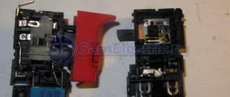
Stop button
The control circuit of any starter is organized using two buttons without fixing the on position. “Stop” is indicated in red to enhance safety. In an emergency, this clear identification speeds up the disconnection of the power source.
Starter connection diagram
In the initial position of the “Stop” button, the circuit is closed. When pressed, the induction coil is disconnected from the current source. The electromagnetic field disappears. The spring returns the armature to its original state while simultaneously opening the main contact group. The secondary closure of the circuit in this section does not matter, since the general break is provided by the “Start” button.
For your information. It should be emphasized that modern starters are compact. Such products are suitable for mounting on a standard DIN rail.
Start button
This control element is produced in black (green) color. In the initial state, the contacts are open. Pressing activates the formation of a magnetic field and the movement of the main contact group. “Self-recovery” ensures the functionality of the working power circuit after the start button is returned to its initial position.
Reversible connection of a three-phase motor
When the switch QF1 is operating , simultaneously all three phases, without exception, are adjacent to the contacts of the starter (KM1 and KM2) and are in this state. In this case, the first stage, which represents power for the control circuit, flowing through the protection device of the control circuit SF1 and the shutdown key SB1, directly supplies voltage to the contacts under the third number, which refers to SB2, SB3. In this case, the existing contact 13NO takes on the role of the main duty officer. In this way, the system is considered completely ready for operation.
System switching during counter rotation
By using the SB2 key, we direct the first phase voltage to the coil, which relates to the KM1 starter. After this, normally open contacts are introduced and normally closed contacts are turned off. In a similar way, by closing the existing contact KM1, the effect of self-capture of the magnetic device occurs. In this case, all three phases, without exception, are supplied to the required winding of the motor, which, in turn, begins to generate rotational movement.
The created model provides for the presence of one working device. For example, only KM1 or, on the contrary, KM2 can function. The marked chain has real elements.
Changing the turning movement
Now, to give the opposite direction of movement, you should change the state of the power phases, which is convenient to do using the KM2 switch. Everything is accomplished thanks to the opening of the first phase. In this case, all contacts without exception will return to their original state, de-energizing the motor winding. This phase is considered standby mode.
Using the SB3 key activates the KM2 electromagnetic starter, which in turn changes the position of the second and third phases. This influence forces the motor to rotate in the opposite direction. Now KM2 will be the leader, and until it is disconnected, KM1 will not be used.
Advantages of implementing such a connection scheme
- The switch and control manipulator (button) can be separated. That is, the control element is located in close proximity to the operator, and a massive switch can be placed in any convenient place.
- It can be controlled using a foot drive (hands remain free). This allows for better control of the electrical installation and for holding the workpiece.
- The remote starter connection diagram allows you to place safety devices. For example, short circuit protection or thermal relays that are triggered by temperature overloads. In addition, this scheme makes it possible to implement mechanical protection: when the moving parts of the electrical installation move to a critical point, the limit switch is triggered and the magnetic starter opens.
- The remote location of the control elements allows the emergency button to be located in a convenient location, which increases operational safety.
- It is possible to install a single push-button station to control a large number of magnetic starters when electrical installations are located in different places and at great distances. The connection diagram through such a post involves the use of low-current control wiring, which saves money on the purchase of expensive power cables.
- To control one starter, you can install several push-button stations. In this case, control of the electrical installation from each post will be equivalent. That is, you can start the electric motor from one point and turn it off from another. Connection diagram for several push-button posts in the illustration:
- Magnetic contactors can be integrated into an electronic control system. In this case, commands to start and shut down electrical installations are given automatically, according to a given algorithm. It is impossible to organize such a system using mechanical (manual) switches.
In fact, such switching is a relay circuit.
Characteristics of circuit breakers using the example of TEXENERGO
A few years ago, I published articles on my blog on choosing circuit breakers and why…
Folk way of choosing
To connect asynchronous electric motors with a squirrel-cage rotor, there is also a “folk” formula, according to which the rated current In of the motor is taken equal to twice the power value in kilowatts, that is, if
P = 3.7 kW, then Inom = 3.7 * 2 = 7.4 A.
Based on this value, a magnetic starter contactor is selected so that its rated operating current is not less than this value. In such calculations it is assumed that contactors with a suitable rated load value are able to withstand the start of electric motors with a multiple excess of starting currents Ip over the operating rated In, therefore the calculation of starting currents is not performed. A starter with a rated current of 10 A is suitable for this connection.
220 volt coil: connection diagrams
To control the operation of the magnetic starter, only two buttons are used - the “Start” button and the “Stop” button. Their design can be different: in a single housing or in separate housings.
Buttons can be in the same housing or in different ones
Buttons produced in separate housings have only 2 contacts, and buttons produced in one housing have 2 pairs of contacts. In addition to the contacts, there may be a terminal for connecting the ground, although modern buttons are produced in protected cases that do not conduct electric current. Push-button stations in a metal case for industrial needs are also produced, which are highly impact resistant. As a rule, they are grounded.
Connection to 220 V network
Connecting a magnetic starter to a 220 V network is the simplest, so it makes sense to start familiarizing yourself with these circuits, of which there may be several.
A voltage of 220 V is supplied directly to the coil of the magnetic starter, which are designated as A1 and A2, which are located in the upper part of the housing, as can be seen from the photo.
Connecting a contactor with a 220 V coil
When a regular 220 V plug with a wire is connected to these contacts, the device will start working after the plug is plugged into a 220 V socket.
Using power contacts, it is permissible to turn on/off an electrical circuit for any voltage, as long as it does not exceed the permissible parameters indicated in the product passport. For example, you can apply battery voltage (12 V) to the contacts, with which a load with an operating voltage of 12 V will be controlled.
It should be noted that it does not matter which contacts the single-phase control voltage is supplied to, in the form of “zero” and “phase”. In this case, the wires from contacts A1 and A2 can be swapped, which will not affect the operation of the entire device.
It is quite natural that such a switching circuit is used extremely rarely, since it requires direct voltage supply to the coil of the magnetic starter. In this case, there are many options for switching on, using a time relay or a twilight sensor, connecting, for example, street lighting to power contacts. The main thing is that the “phase” and “zero” are nearby.
Using the Start and Stop buttons
Basically, magnetic starters are involved in the operation of electric motors. Without the presence of the “Start” and “Stop” buttons, such work is associated with a number of difficulties. This is primarily due to the operating characteristics of electric motors, which are often located at a considerable distance. The buttons are connected to the coil circuit in series, as in the figure below.
Switching diagram of a magnetic starter with buttons
This method is characterized by the fact that the magnetic starter will be in working condition as long as the “Start” button is pressed, which is very inconvenient. In this regard, the circuit includes additional (BC) contacts of the magnetic starter, which duplicate the operation of the “Start” button. When the magnetic starter is turned on, they close, so after releasing the “Start” button, the circuit remains operational. They are designated in the diagram as NO (13) and NO (14).
Connection diagram for a magnetic starter with a 220 V coil and a self-retaining circuit
You can turn off running equipment only using the “Stop” button, which breaks the electrical power supply circuit of the magnetic starter and the entire circuit. If the circuit provides other protection, for example, thermal, then if it is triggered, the circuit will also be inoperable.
Power for the motor is taken from the T contacts, and power is supplied to the magnetic starter contacts, designated L.
This video explains in detail and shows in what order all the wires are connected. In this example, a button (button post) is used, made in one housing. As a load, you can connect a measuring device, an ordinary incandescent lamp, a household appliance, etc., operating from a 220 V network.
How to connect a magnetic starter. Connection diagram.
Watch this video on YouTube
Starter Maintenance
Like any equipment, this electrical device periodically requires maintenance. The minimum maintenance program includes:
- Visual inspection. Damage and chips may occur due to prolonged use of the device. Therefore, it is necessary to check the appearance of the starter for damage and the presence of all parts and components. It is necessary to remove dirt from the body and from the surface of the core.
- Cleaning contacts. If there are traces of melting or carbon deposits on the contacts, then you need to clean them with a needle file.
- Mechanical check. The spring is inspected, it should be rigid, the coils should be at a distance from each other. The absence of jamming of the armature stroke is checked, and if it is detected, the rubbing parts are lubricated or ground.
- Checking the coil. If there are cracks on the body, melted insulation or carbon deposits on the contacts, the coil must be replaced. A hum during operation of the device indicates an interturn short circuit. Over time, the active resistance of the coil decreases. In all these cases, it is better to rewind or replace it.
- Monitoring the absence of a short circuit. If the device in the housing has metal parts, you need to make sure that there is no short circuit between them.
- Checking the thermal relay. If a thermal relay is installed on the 220 V magnetic starter, it is necessary to check the adjustment settings of this relay. It is problematic to do this at home; special test benches are needed for this.
Connection diagrams for a magnetic starter with a 220 V coil
Before we move on to the diagrams, let’s figure out what and how these devices can be connected. Most often, two buttons are required - “start” and “stop”. They can be made in separate housings, or they can be a single housing. This is the so-called push-button post.
Buttons can be in the same housing or in different ones
Everything is clear with individual buttons - they have two contacts. One receives power, the other leaves it. There are two groups of contacts in the post - two for each button: two for start, two for stop, each group on its own side. There is also usually a ground terminal. Nothing complicated either.
Connecting a starter with a 220 V coil to the network
Actually, there are many options for connecting contactors; we will describe a few. The diagram for connecting a magnetic starter to a single-phase network is simpler, so let's start with it - it will be easier to understand further.
Power, in this case 220 V, is supplied to the coil terminals, which are designated A1 and A2. Both of these contacts are located at the top of the case (see photo).
This is where you can supply power to the coil.
If you connect a cord with a plug to these contacts (as in the photo), the device will be in operation after the plug is inserted into the socket. In this case, any voltage can be applied to the power contacts L1, L2, L3, and it can be removed when the starter is triggered from contacts T1, T2 and T3, respectively. For example, a constant voltage from a battery can be supplied to the inputs L1 and L2, which will power some device that will need to be connected to the outputs T1 and T2.
Connecting a contactor with a 220 V coil
When connecting single-phase power to the coil, it does not matter which output is supplied with zero and which with phase. You can switch the wires. Even most often, the phase is supplied to A2, since for convenience this contact is located on the bottom side of the case
And in some cases it is more convenient to use it and connect the “zero” to A1
Even most often, the phase is supplied to A2, since for convenience this contact is located on the bottom side of the housing. And in some cases it is more convenient to use it and connect the “zero” to A1.
But, as you understand, this scheme for connecting a magnetic starter is not particularly convenient - you can also supply conductors directly from the power source by building in a regular switch. But there are much more interesting options. For example, you can supply power to the coil through a time relay or a light sensor, and connect the street lighting power line to the contacts. In this case, the phase is connected to contact L1, and zero can be taken by connecting to the corresponding coil output connector (in the photo above it is A2).
Diagram with start and stop buttons
Magnetic starters are most often installed to turn on an electric motor. It is more convenient to work in this mode if there are “start” and “stop” buttons. They are connected in series to the phase supply circuit to the output of the magnetic coil. In this case, the diagram looks like the figure below
note that
Switching diagram of a magnetic starter with buttons
But with this method of switching on, the starter will operate only as long as the “start” button is held down, and this is not what is required for long-term operation of the engine. Therefore, a so-called self-catching circuit is added to the circuit. It is implemented using auxiliary contacts on the starter NO 13 and NO 14, which are connected in parallel with the start button.
Connection diagram for a magnetic starter with a 220 V coil and a self-retaining circuit
In this case, after the START button returns to its original state, power continues to flow through these closed contacts, since the magnet has already been attracted. And power is supplied until the circuit is broken by pressing the “stop” key or by triggering a thermal relay, if there is one in the circuit.
Power for the motor or any other load (phase from 220 V) is supplied to any of the contacts marked with the letter L, and is removed from the contact marked T located underneath it.
It is shown in detail in what order it is better to connect the wires in the following video. The whole difference is that not two separate buttons are used, but a push-button post or push-button station. Instead of a voltmeter, you can connect a motor, pump, lighting, or any device that operates on a 220 V network.
What is it used for?
This is a switching type device. It is needed to connect equipment to the network or de-energize it. It is designed to operate with voltages not exceeding 1000 V. This device can be used in the following cases:
- When the street lights are turned on.
- For controlling powerful asynchronous motors.
- Can be used to work with external or internal lighting of industrial facilities.
- When switching devices for warming up. An example is infrared heaters or heating elements.
- Application as starting equipment for industrial automation systems.
The need to select magnetic starters arises when installing the appropriate equipment or during its repair.
How to choose a starter is described in the video:
How to connect a 220V starter with a button
The most common switching scheme is a single-phase consumer with a push-button start. Moreover, the buttons should be spaced apart: “start” separately, “stop” separately. To understand how to connect a magnetic starter, let’s draw a combined diagram showing the parts:
In our case, we use a single-phase power source (220 V), separated control buttons, a protective thermal relay, and the magnetic starter itself. The consumer is a powerful electric motor.
- The neutral cable (N) is connected simultaneously to the electric motor and the control circuit contacts.
- The “stop” button (Kn2) is normally closed: when released, electric current flows through it.
- The phase line (F) is controlled by a thermal relay (TP) protective circuit and is connected to the input operating contacts of the starter (PM1).
- The starting electrical circuit from the phase is connected to the winding of the starter solenoid (PM) through closed (without overheating) contacts of the thermal relay (TP-1).
- In parallel with the normally open “start” button (Kn1), the contacts of the service circuit of the magnetic starter (PM4) are connected.
- When the start button is pressed, electric current flows through the contactor solenoid. The contacts (PM1) - power supply to the electric motor and (PM4) - power supply to the starter solenoid close. After releasing the “start” button, the control and power circuits remain closed, the circuit is in the “on” mode.
- When the line overheats, the thermal relay (TP) is triggered, the normally closed contacts (TP1-) break the solenoid circuit, the contactor opens, and the consumer is switched off. You can turn it on again after the thermostat has cooled down.
- To force the consumer to de-energize, just touch the “stop” button (Kn2), the solenoid power circuit will open, and the consumer’s power will stop.
This key connection scheme for a 220 V magnetic starter allows you to safely use powerful electrical installations and provides additional protection in case of current line overheating. For example, if the motor shaft stops under load.
A simplified diagram (without protective devices and thermal relays) in the illustration:
In this case, the solenoid (and, accordingly, the power contact groups) is controlled manually using two buttons.
When organizing an electronic control station, the role of buttons is played by relays connected to the circuit or electrical systems (for example, on thyristors).
Read also: Device for drilling bolts
As a bonus, consider connecting using an outlet with a timer. In this case, the switching circuit works without a “stop” button. That is, in the presence of control voltage (from the timer), the electrical installation operates.
Stop button.
If the temperature in any of these phases reaches a critical value, an automatic shutdown occurs. The principle of the circuit is based on the electromagnetic induction of the coil used with auxiliary and working contacts.
The MP contactor turns on the control pulse that comes from the start button after it is pressed. At the same time, in the description of similar AB-2M it is written, and on the starter itself with the same rectifier, I saw the inscription B 50Hz. You are right. Due to this feature, they are used in circuits with higher power than starters.
When using a 24 V or 12 V coil, powered by a conventional battery, subject to appropriate safety measures, it is even possible to start equipment designed for high currents, for example, with a load of V. A starter is simply a switching device through which the supply voltage is supplied to the electric motor windings. But we know that the starting current of the engine is much higher than the operating current, which means that an ordinary household machine with a current of 3A will operate immediately when such an engine is started. Reverse Motor Wiring Diagram Some devices work with motors that can rotate in both directions. Connecting an electromagnetic starter with a 220 volt coil
https://youtube.com/watch?v=Wo6HKMpJQ6Q
The best models of automatic fuses
Russian models
The Russian industry for the production of automatic fuses has recently made a big leap. New technologies for manufacturing cases are used. The contact group is meeting in a new way. Improved design. For individuals and businesses, the choice of introductory machines has become much wider and the quality is no worse than the best European brands.
Contactor
Rating: 4.7
The domestic enterprise “Kontactor” is in first place in our ranking. The plant initially made classic automatic machines. Now it is reoriented to industrial designs of 380 V. The company’s line also includes a household series “KPRO” with support for current up to 100 A. But basically the “Contactor” specification is industrial samples for electric motors designed for current up to 1600 A, which should protect industrial equipment. The Proton line also includes models of the three-phase Electron circuit breaker with a rating of 6300 A.
Advantages
- models are equipped with regulation of operation during short circuit or overload;
- a wide range of automatic machines from 16 to 6000 A;
- All products are certified for sale in the Customs Union.
Minuses
- the design is not very well developed;
- There are very few switches for household use;
- high cost of models;
- the mounting contacts are not recessed into the automatic fuse.
KEAZ
Rating: 4.7
A factory with history. The company opened back in 1945. It produces both classic machines and devices of the KEAZ Optima brand, in which one can notice new machine capacities and know-how.
They produce machines for both alternating current and direct current. All electrical equipment adjusters note the good design of the devices and the ease of their installation. If you are choosing which machines to install in a private home, this is the place for you.
Advantages
- there are different types - you can choose protection for different lines that use both direct and alternating current;
- acceptable price;
- compact design.
Flaws
short service life (1–2 years).
DEKraft
Rating: 4.6
Electric machines under the general brand DEKraft are produced at the Russian enterprise Delixi Electric. These products are widely known not only in Russia and the CIS but also abroad.
True, in Europe they are better known by a different name - Himel. Mainly concentrated in China for reasons of reducing the cost of final products.
This policy made it possible to reduce the price of the machine and extend its service life. It was announced that the circuit breaker will withstand at least 6000 contact opening cycles during a short circuit. And with a slow increase in load, when the wiring is already starting to heat up, the circuit breaker can disconnect the electrical circuit at least 25,000 times!
Advantages
- all company enterprises have passed international certification;
- wholesale supply is well established in all regions of Russia;
- it is easy for the buyer to understand which machine is in front of him - all the signatures are in Russian.
Flaws
- maximum current 63 A;
- The maximum permissible cross-section of supply cables is 25 mm².
The best foreign companies
Foreign brands are still popular in our country. It is believed that these are higher quality and durable products. Therefore, our review presents products from foreign manufacturers.
ABB
Rating: 4.9
This bright red acronym is well known to professional electricians due to its wide range of circuit breakers from 0.5 to 100 A.
Both ordinary users and professionals note the reliable plastic case and control lever, which will not break off even after repeated off/on cycles. It’s not for nothing that professional electricians choose these circuit breakers for apartment switchboards.
Advantages
- The dimensions of the breaker body allow it to be easily installed in the panel;
- high level of security;
- ease of installation;
- You can also purchase four-pole models of circuit breakers.
Flaws
- high cost;
- DIN rail mounts are quite fragile;
- no or few type D devices.
Legrand
Rating: 4.8
In the catalog of the French company, you can choose machines of the DRX series - corresponding to the load for industrial use and the DX, RX, TX series for domestic use. The housings of the devices in the apartment are dustproof.
Current ratings range from 6 A to 630 A, including 125, 260, 320 and 400 A. Such a wide range allows you to select a fuse for both domestic needs and large-scale industries.
Advantages
- there are machines with poles from 1 to 4;
- There is a laser barcode on the case.
Flaws
- rarely, but there are models with defects;
- the toggle switch is carelessly executed;
- high cost.