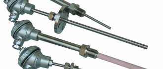
In process automation, it is very often necessary to take indicators of temperature changes in order to load them into control systems for the purpose of further processing. This requires high-precision, low-inertia sensors that can withstand high temperature loads within a certain measurement range. Thermocouples are widely used as thermoelectric converters - differential devices that convert thermal energy into electrical energy.
The devices are also a simple and convenient temperature sensor for a thermoelectric thermometer designed to make accurate measurements over fairly wide temperature ranges. In particular, the control automation of gas boilers and other heating systems is triggered by an electrical signal coming from a thermocouple-based sensor. The sensor designs provide the necessary measurement accuracy in the selected temperature range.
Device and principle of operation
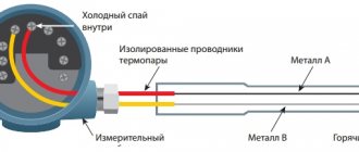
The thermocouple is structurally composed of two wires, each of which is made of different alloys. The ends of these conductors form a contact (hot junction) made by twisting, using a narrow weld or butt welding. The free ends of the thermocouple are closed using compensation wires to the contacts of the measuring device or connected to an automatic control device. At the connection points another so-called cold junction is formed. The device is shown schematically in Figure 1.
Rice. 1. Scheme of the thermocouple structure
The hot junction area is highlighted in red, the cold junction is highlighted in blue.
The electrodes consist of different metals (metal A and metal B), which are painted in different colors in the diagram. In order to protect thermoelectrodes from aggressive hot environments, they are placed in a sealed capsule filled with an inert gas or liquid. Sometimes ceramic beads are placed on the electrodes, as shown in Fig. 2).
Rice. 2. Thermocouple with ceramic beads
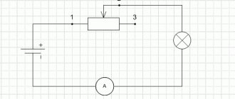
The operating principle is based on the thermoelectric effect. When a circuit is closed, for example with a millivoltmeter (see Fig. 3), a thermo-emf occurs at the junction points. But if the electrode contacts are at the same temperature, then these EMFs compensate each other and no current occurs. However, if you heat the hot solder joint with a torch, then, according to the Seebeck effect, a potential difference will arise, supporting the existence of an electric current in the circuit.
Rice. 3. Measuring voltage on TC wires
It is noteworthy that the voltage at the cold ends of the electrodes depends proportionally on the temperature in the hot junction area. In other words, in a certain temperature range we observe a linear thermoelectric characteristic that displays the dependence of the voltage on the magnitude of the temperature difference between the hot and cold junction points. Strictly speaking, we can talk about linearity of indicators only in the case when the temperature in the cold junction region is constant. This should be taken into account when calibrating thermocouples. If the temperature changes at the cold ends of the electrodes, the measurement error can be quite significant.
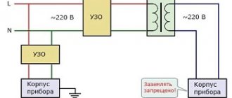
In cases where it is necessary to achieve high accuracy of indicators, the cold junctions of the measuring transducers are even placed in special chambers in which the temperature environment is maintained at the same level by special electronic devices using data from a resistance thermometer (the diagram is shown in Fig. 4). With this approach, it is possible to achieve measurement accuracy with an error of up to ± 0.01 °C. True, such high precision is needed only in a few technological processes. In some cases, the requirements are not so stringent and the error can be an order of magnitude lower.
Rice. 4. Solving the issue of accuracy of thermocouple readings
The error is affected not only by temperature changes in the environment surrounding the cold junction. The accuracy of the readings depends on the type of construction, wiring diagram, and some other parameters.
Publications
Journal "World of Measurements", No. 1, 2002. Karzhavin A.V., Ulanovsky A.A.
From the theory of thermoelectricity
Temperature is one of the most important controlled parameters of technological processes in almost all sectors of the national economy. The majority of all temperature measurements are made by thermoelectric converters [1, p. 8], the operating principle of which is based on the Seebeck phenomenon.
In 1821, a German scientist, a native of Revel (now Tallinn), T. J. Seebeck (1770-1831) discovered that if the junctions of two dissimilar metals forming a closed electrical circuit have different temperatures, then an electric current flows in the circuit. A change in sign of the junction temperature difference is accompanied by a change in the direction of the current.
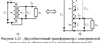
This fact served as the basis for the creation of a device whose sensitive element is a thermocouple - two conductors made of dissimilar materials connected to each other at one (working) end, the other two (free) ends of the conductors are connected to a measuring circuit or directly to a measuring device, and the temperature of the free is ultimately known in advance. A thermocouple forms a device (or part thereof) that uses the thermoelectric effect to measure temperature. The thermoelectric effect refers to the generation of thermoelectromotive force (thermoEMF) arising due to the temperature difference between two compounds of different metals and alloys (Fig. 1) forming part of the same circuit.
Rice. 1 Ideal thermocouple
For an infinitesimal temperature difference dT
junctions of a thermocouple consisting of conductors A and B, its thermoEMF is determined by the dependence
EAB = eAB*dT,
where
eAB
is the differential thermoEMF of pair AB.
The value of eAB
is also called the thermoEMF coefficient, the Seebeck coefficient or the sensitivity of the thermocouple.
The thermoEMF of a thermocouple is caused by three reasons [2]. The first is the dependence of the Fermi level of electron energy in a conductor on temperature, which leads to unequal potential jumps when moving from one metal to another from thermocouple junctions located at different temperatures. Secondly, in the presence of a temperature gradient, electrons in the region of the hot end of the conductor acquire higher energies and mobility. A gradient of electron concentration with increased energy values will arise along the conductor, which will entail the diffusion of faster electrons to the cold end, and slower ones to the hot end. But the diffusion flux of fast electrons will be greater. In addition, in the presence of a temperature gradient along the conductor, a drift of phonons—quanta of vibration energy of the crystal lattice—occurs. Colliding with electrons, phonons impart directional movement to them from the hotter end of the conductor to the colder one. The last two processes lead to an excess of electrons near the cold end and a shortage of them near the hot end. As a result, an electric field appears inside the conductor, directed towards the temperature gradient. Thus, the thermoEMF of a thermocouple arises only due to the presence of a longitudinal temperature gradient in the conductors that make up the pair.
Differential thermo-EMF (sensitivity) of thermocouple eAB
represents the difference between the absolute specific thermo-emf coefficients
A
and
B
of each thermocouple conductor:
eAB = dEAB / dT = A - B,
which can be considered constant only over a narrow temperature range. The absolute thermo-emf coefficient of a given conductor can be determined from the measured Peltier or Thomson heat. The Peltier phenomenon (1834) is that when an electric current flows through a circuit composed of dissimilar conductors, heat is released or absorbed at the point of contact of the conductors, depending on the direction of the current. The amount of heat released or absorbed at the junction QAB
proportional to the charge
q
passed through the junction:
QAB = AB*q = AB*I*t,
where: AB is the Peltier coefficient, V; I—current strength, A; t—time, s.
Thomson's phenomenon (1856) is that when an electric current passes through a homogeneous conductor along which there is a temperature gradient, heat is generated or absorbed in the conductor depending on the direction of the current. This heat is released (absorbed) in addition to the released Joule-Lenz heat (resistive heating). Thomson heat is proportional to the current strength I and the temperature gradient T:, where is the Thomson coefficient, V/K-1. Thomson heat is a characteristic of a conductor material, similar to electrical resistivity and thermal conductivity. Applying the laws of thermodynamics to the three indicated thermoelectric phenomena, Thomson derived the following relationships that make it possible to determine the Peltier and Seebeck coefficients (thermo-emf coefficient):
The presence of information on the absolute thermoEMF coefficient for at least one conductor material makes it possible to determine the absolute coefficients of all conductors based on the results of thermoEMF measurements relative to this conductor. Lead is used as such a standard at low temperatures, and platinum at medium and high temperatures.
For most thermocouples, the differential thermo-EMF significantly depends on temperature and the dependence of thermo-EMF on temperature can be presented in integral form as: , which, in turn, can be approximated with a given accuracy in the operating temperature range (T1 ... T2) in the form of a polynomial n
-th degree:
The widespread use of thermocouples in industry is due primarily to their simplicity, ease of installation, and the ability to measure local temperature. The advantages of thermocouples also include a wide range of measured temperatures, low inertia, and the ability to measure small temperature differences. Thermocouples can provide highly accurate temperature measurements at ±0.01°C.
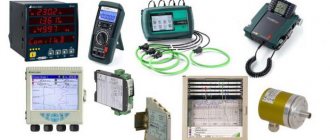
Thermoelectric converters, main types and applications
According to GOST 6616-94, the types of thermocouples are standardized in the CIS countries, the most common of which are presented in table. 1.
Table 1
| Thermocouple type | IEC designation | Lit. designation NSH | Chemical composition of thermoelectrodes, wt. % | Limits of measured temperatures | |||
| positive | negative | lower | upper | Short-term | |||
| Copper - constantan TMKn | Cu-CuNi | T | Cu | Cu + (40-45)Ni + 1.0Mn + 0.7Fe | -200 | 350 | 400 |
| Chromel-copel THC | — | L | Ni + 9.5 Cr | Cu + (42-44)Ni + 0.5Mn + 0.1Fe | -200 | 600 | 800 |
| Chromel - constantan THCn | NiCr-CuNi | E | Ni + 9.5 Cr | Cu + (40-45)Ni + 1.0Mn + 0.7Fe | -200 | 700 | 900 |
| Iron - constantan TFA | Fe-CuNi | J | Fe | Cu + (40-45)Ni + 1.0Mn + 0.7Fe | -200 | 750 | 900 |
| Chromel-alumel TCA | NiCr-NiAl | K | Ni + 9.5 Cr | Ni + 1Si + 2Al + 2.5Mn | -200 | 1200 | 1300 |
| Nichrosil-nisilic TNN | NiCrSi-NiSi | N | Ni + 14.2Cr + 1.4Si | Ni + 4.4Si + 0.1Mg | -270 | 1200 | 1300 |
| Platinum-rhodium-platinum Chamber of Commerce and Industry13 | — | R | Pt+13Rh | Pt | 0 | 1300 | 1600 |
| Platinum-rhodium-platinum Chamber of Commerce and Industry10 | — | S | Pt+10Rh | Pt | 0 | 1300 | 1600 |
| Platinorhodium-platinumrhodium | — | B | Pt+30Rh | Pt+6Rh | 600 | 1700 | — |
| Tungsten-rhenium-tungsten (A-1; A-2; A-3) | — | — | W+5%Re | W+20%Re | 0 | 2200 | 2500 |
Notes:
1. The indicated letter designations of the nominal static characteristic (NSC) of thermocouples correspond to the designations of the IEC 584-1 standard, except for the Chromel-Kopel thermocouple (L), which is not standardized by this standard.
2. According to the German standard DIN 43710, type L corresponds to a Fe-CuNi (iron-copper-nickel) thermocouple, the negative thermoelectrode of which is closer in composition to Copel and the thermocouple develops a slightly higher thermo-EMF than an iron-constantan (J) thermocouple.
3. Thermoelectrode materials are usually supplied in accordance with the tolerance limits normalized for temperatures above -40°C. To measure low temperatures, when ordering thermoelectrode materials, requirements for permissible deviations must be specified, corresponding, as a rule, to class 3.
4. The operating range of the thermal converter may be within the range of measured temperatures.
The upper limit of the operating temperature range is considered the maximum temperature for long-term use (1000 hours) of the thermal converter. During this period, the change in the static characteristics of the thermocouple relative to the nominal one should not exceed 1%. Short-term use is considered to be operation of a thermal converter for up to 100 hours. During this time, the static characteristic of the thermocouple should also not change by more than 1% [3, p. 83].
Table 2 shows the recommended operating atmospheres for the use of the above types of thermocouples, as well as their differential sensitivity in the specified temperature ranges [1, p. 34].
From Table 2 it can be seen that there are two universal thermocouples: copper-constantan and iron-constantan. The first has not found wide application in industry due to the narrow temperature range in the region above 0°C. It is mainly used to measure low temperatures. The J-type thermocouple is widely used in the West, but has not found widespread use in Russia either, apparently due to the lack of production of high-purity thermoelectrode iron. In addition, the disadvantages of a thermocouple include poor corrosion resistance of the iron electrode and high sensitivity to deformation.
table 2
| Thermocouple type | Working atmospheres | Sensitivity over temperature range | ||||
| oxidative | restorative | inert | vacuum | range, °С | dE/dT, µV/°С | |
| TMKn (T) | ++ | + | + | + | 0-400 | 40-60 |
| THC | ++ | — | + | + | 0-600 | 64-88 |
| THKn (E) | ++ | — | + | + | 0-600 | 59-81 |
| TFA (J) | ++ | ++ | + | + | 0-800 | 50-64 |
| TXA (K) | ++ | — | + | + | 0-1300 | 35-42 |
| TNN (N) | ++ | — | + | + | 0-1300 | 26-36 |
| CCI (R, S) | ++ | — | + | + | 600-1600 | 10-14 |
| TPR (B) | ++ | — | + | + | 1000-1800 | 8-12 |
| TVR | — | H2++ | ++ | ++ | 1300-2500 | 14-7 |
Notes:
1. ++ recommended atmosphere; + operation in this atmosphere is possible; - not a recommended atmosphere.
2. An oxidizing atmosphere usually means air (21% vol. O2) or a mixture of gases with an excess of oxygen, in which oxidation of a substance occurs (loss of electrons by atoms and ions). The addition of oxygen atoms (oxide formation) is a special case of oxidation reactions. A weakly oxidizing atmosphere contains O2 in the gas mixture at a level of 2-3%. In a reducing atmosphere, chemical reactions take place in which atoms and ions gain electrons. In this case, the valency of the element decreases. Examples of reducing media are dry H2, CO, carbon-containing gas media, endogas, exogas, dissociated ammonia, exhaust gases from combustion chambers. An inert atmosphere exists in gases N2, Ar, He.
The main thermocouples for metallurgical production in the range of 1100-1600°C are platinum-rhodium-platinum thermocouples TPP10 and TPR, modification TPP13 is widely used in the West. TPP10 thermocouples are also used as reference temperature measuring instruments. Based on the combination of their properties, platinum and platinum-rhodium alloys are unique materials for thermocouples. Their main property is good resistance to gas corrosion, especially in air at high temperatures. This property, combined with a high melting point and a fairly large thermo-emf, good compatibility with many insulating and protective materials, as well as good manufacturability and reproducibility of metrological properties, makes thermocouples indispensable for the manufacture of thermocouple electrodes that measure high temperatures in oxidizing environments. These alloys are stable in argon and helium, do not dissolve nitrogen and hydrogen and do not form nitrides and hydrides, and do not interact with CO and CO2. However, the use of platinum-rhodium-platinum thermocouples in reducing atmospheres is not recommended, because in this case, contamination of platinum and platinum-rhodium occurs with elements recovered from protective or insulating ceramics (usually oxide). Up to 1200°C, platinum and its alloys with rhodium practically do not interact with refractory materials. At higher temperatures, contact with SiO2 leads to a change in thermoEMF, which in a reducing atmosphere, already at temperatures above 1100°C, leads to the destruction of platinum due to the formation of Pt5Si2 silicides and low-melting (830°C) Pt-Pt5Si2 eutectic deposited along grain boundaries. This reaction is possible only in the presence of carbon and sulfur and is carried out by reducing SiO2 to Si, which, in the presence of CO, combines with sulfur to form gaseous SiS2, the latter reacting with platinum. Thus, the reaction proceeds through the gas phase and does not require mandatory contact of thermoelectrodes with quartz. SiO2 can also be reduced by hydrogen to SiO (gas), which also reacts with platinum. In general, silicon is the main cause of embrittlement and destruction of thermocouples. It, like some other elements: Zn, Sn, Sb, Pb, As, Bi, P, B, S, belong to platinum poisons [4]. Sulfur and carbon are commonly present in residues from lubricating oils and cooling emulsions (used in the manufacture of metal boot protection fittings). Vapors of iron, chromium and manganese also pose a danger to platinum thermoelectrodes, especially in a vacuum. Interaction with metal vapors leads to a strong thermoEMF drift and premature destruction of the thermocouple. For this reason, platinum thermocouples are never installed directly in metal cases. The upper temperature limit for long-term use of the TPP10 thermocouple, equal to 1300°C, is limited by the catastrophic grain growth of the platinum electrode at temperatures above 1400°C. In this range, a TPR thermocouple is used, with lower differential sensitivity, but with an upper operating temperature limit of up to 1600°C. This thermocouple is mechanically stronger, less prone to grain growth and embrittlement, and less sensitive to contamination. In addition, the low sensitivity of the thermocouple in the range of 0-100°C makes it possible to use a thermocouple with copper extension wires.
For stable operation of thermocouples made of platinum and its alloys, reliable insulation of thermoelectrodes with high-purity oxide ceramics is required, as well as protection with good quality corundum (Al2O3) covers. However, the gas-tight corundum cover with a minimum content of impurities has a relatively low heat resistance. Good resistance to thermal shock (temperature jump of at least 250°C) is demonstrated by ceramics with a low Al2O3 content (70-80%) and porosity of 5-10%. Therefore, Western and some Russian manufacturers produce platinum thermal converters in double protective covers: the outer one is heat-resistant from porous ceramics with an Al2O3 content of 80% and the inner one is gas-tight from high-purity ceramics (99.5% Al2O3). If there are abrasive particles in the working environment, the outer cover can be made of self-bonded silicon carbide, which also has high heat resistance. Detailed information on the protection of thermocouples at high temperatures is presented in [5, p. 252-261 and 350-357].
The disadvantages of thermocouples made of precious metals include the already mentioned high sensitivity of thermoelectrodes to any contamination that appears during the manufacture, installation or operation of thermocouples, as well as their high cost.
Tungsten-rhenium thermocouples TVR have the highest limit for long-term use of 2200°C, but only in non-oxidizing environments, because catastrophic oxidation and destruction of thermoelectrodes occurs already at a temperature of 600°C. The thermocouple is stable in argon, helium, dry hydrogen and nitrogen, as well as in vacuum. The main disadvantage is the poor reproducibility of thermo-EMF, which forces thermoelectrode pairs to be grouped into groups with nominal static characteristics A-1, A-2, A-3.
The most common types of thermocouples in Russian industry are the chromel-copel thermocouple (in the West a similar chromel-constantan thermocouple, type E is used) with a long-term use temperature of up to 600°C and a chromel-alumel thermocouple (type K) with a long-term use temperature of up to 1200°C (see Table 1).
The Chromel-Kopel thermocouple has the highest differential sensitivity of all industrial thermocouples and is used for accurate temperature measurements as well as for measuring small temperature differences. Thermocouples are characterized by exceptionally high thermoelectric stability at temperatures up to 600°C, due to the fact that changes in the thermo-EMF of the Chromel and Copel thermoelectrodes are directed in the same direction and compensate each other. The technical life of thermocouples is several tens of thousands of hours. Disadvantage: high sensitivity to deformation.
The chromel-alumel thermocouple is the most common thermocouple in industry and scientific research with a long-term use temperature of 1200°C. The RF standard GOSTR 50431-92 and earlier standards indicate a long-term operating temperature of 1000°C. Based on numerous experimental data, the value of 1200°C seems to be somewhat overestimated.
Chromel-alumel and chromel-copel thermocouples are designed for temperature measurement in oxidizing and inert environments. The oxygen content in the oxidizing atmosphere must be at least several percent or its presence must be practically eliminated. In an atmosphere containing less than 2-3% (volume) oxygen in chromel, the selective oxidation of chromium sharply increases, which leads to a significant decrease in the thermoEMF of chromel, and the intercrystalline nature of corrosion leads to embrittlement (“green rot”). A long stay in a vacuum at high temperatures greatly reduces the thermo-emf of chromel due to the evaporation of chromium. In an atmosphere containing sulfur, intercrystalline corrosion embrittles thermoelectrodes, primarily alumel. In addition, SO2 strongly oxidizes chromel and is therefore the cause of a large negative thermoEMF drift. The working life of TCA thermocouples at temperatures below 850°C is limited only by the value of the thermo-EMF drift, and at 1000-1200°C - by the heat resistance of the thermoelectrodes.
The TXA thermocouple has a wide range of measured temperatures, but it is impractical to use it over the entire range, because this degrades the measurement accuracy. A thermocouple used to accurately measure temperatures up to 500°C should not measure higher temperatures and, conversely, a thermocouple used at temperatures above 900°C should not measure temperatures 300-600°C. At high temperatures, local inhomogeneities are formed in thermoelectrodes, and thermoEMF drift occurs. Therefore, it is impossible to reduce the depth of immersion of the thermocouple into the working environment, because the resulting local inhomogeneities can fall into the temperature gradient zone and lead to additional measurement errors. Increasing the diving depth does not cause additional error.
In TXA thermocouples, two types of thermoEMF instability are observed: irreversible instability, gradually accumulating over time, and reversible cyclic instability. The first type of instability is caused by the interaction of thermoelectrodes with the environment. The thermoEMF drift in degrees is no more than 1% of the measured temperature at the level of 1000°C for 1000-4000 hours with a thermoelectrode diameter of more than 1 mm [1, p. 81]. The second type of instability is due to the occurrence of transformations in chromel according to the type of short-range ordering of the magnetic cells of the alloy structure in the range of 250-550°C. As a result of these transformations, TXA thermocouples in the delivered state after heating at 250-550°C increase the thermoEMF relative to the nominal values. This growth disappears (the magnetic structure becomes disordered) after heating at higher temperatures. The magnitude of the reversible thermoEMF drift depends on the previous history of the thermoelectrodes, calibration temperatures, cooling rate, and also on the gradient of the temperature field in which the thermocouple is located. The drift can reach 3-4°C. To reduce reversible drift, it is useful to use chromel subjected to preliminary heat treatment “for ordering” at 425-475°C for 6 hours [1, p. 89], however, it is not possible to completely eliminate it if the temperature is measured with a thermocouple over a wide range. That is why ABB Automation Products (Germany) supplies its thermoelectrode materials for K-type thermocouples only after additional “annealing for ordering”. The magnetic structure of the chromel electrode in this case is already ordered, and after installing the thermocouple on the thermometered object in the area of thermoelectrodes with a temperature gradient of 250-550°C, this process no longer manifests itself.
All these problems with the TXA thermocouple initiated the development and standardization by leading industrial countries of the nirosil-nisil thermocouple, created by the materials science laboratory of the Australian Department of Defense in the 60s. The thermoelectrode materials nicrosil and nisil demonstrate significantly better thermoEMF stability compared to the TXA thermocouple. This was achieved by increasing the concentration of chromium and silicon in nickel, as well as by introducing magnesium into nisil, which transferred the oxidation process of the thermoelectrode material from internal intercrystalline to surface. In this case, a protective film of oxides is formed on the thermoelectrodes, suppressing further oxidation. Increasing the chromium content of nicrosil to 14.2% virtually eliminated the reversible instability characteristic of chromel. The new alloys also showed high radiation resistance, because they do not contain activating impurities Mn, Co, Fe. The drift of a TNN thermocouple with thermoelectrodes with a diameter of 3.2 mm over 1100 hours in air at a temperature of 1200°C does not exceed 100 μV, while the drift of the same TXA thermocouple over 300 hours reached 300 μV [6]. These data also indicate an overestimated value of the long-term use temperature of 1200°C for the TXA thermocouple. The work [6] concludes that there is significant irreversible instability of the TCA thermocouple at temperatures above 1050°C. On the contrary, a TNN thermocouple with a thermoelectrode diameter of at least 2.5 mm and a temperature of up to 1200°C demonstrates a thermo-EMF drift that does not exceed the drift of thermocouples made of precious metals (TPP, TPR). The prospects for using the TNN thermocouple as a universal means of measuring temperatures in the temperature range 0-1230°C are shown; this will increase the accuracy of industrial measurements, the quality of the final product and, ultimately, the efficiency of the entire production.
Protective covers for thermal converters
Protective gas-tight covers of thermal converters significantly expand the range of application of thermocouples in aggressive environments and increase their service life [5, pp. 345-349]. For temperatures up to 800°C, cases made of stainless steel type X18N10T or 10Kh17N13M2T are used (increased resistance to intergranular corrosion), at higher temperatures, mainly ferritic steel 15Kh25T was used with an intense scaling temperature of 1050°C, which has limited weldability and is prone to embrittlement in the range of 450-850°C [7, p.353]. Currently, TXA thermocouples are also produced in protective covers made of heat-resistant austenitic steel type X23N18, with the same heat resistance combined with good weldability. For operation at temperatures above 1000°C, the consumer is offered TXA thermocouples in cases made of KhN78T and KhN45Yu alloys on nickel and iron-nickel bases, respectively. According to GOST 5632-72, the temperature of intense scaling of the KhN78T alloy is 1150°C, the recommended maximum temperature for long-term use of the KhN45Yu alloy in air is 1250-1300°C, i.e. it covers the entire range of measured temperatures of the TXA thermocouple. It is only necessary to take into account that the XN78T alloy is especially sensitive to the sulfur content in the working environment due to the high nickel content in the alloy. The formation of low-melting nickel sulfide compounds leads to destruction of the cover. The XN45Yu alloy has excellent heat resistance, maintaining good corrosion resistance due to the inclusion of 3.4% Al in the alloy, which forms a refractory oxide film on the surface of the alloy and prevents the development of the corrosion process. The corrosion rates of these alloys are 7-10 times less than 15Х25Т steel under the same operating conditions.
It should be noted that in Russia there is not enough production of thermocouples in protective cases intended for special applications. Universal covers cannot solve the problem of protecting thermocouples in many aggressive environments.
Cable thermoelectric converters
Currently widespread in the world, incl. and in Russia, they received thermocouple cables, which are a pair of thermoelectrodes placed inside a metal tube and insulated from it with compacted fused MgO-periclase powder (see Fig. 2).
Rice. 2 A thermocouple cable blank with one or two pairs of thermoelectrodes
In Russia, they produce thermocouple cable of two types KTMS-XA and KTMS-HK with diameters from 1 to 7.2 mm according to TU 16-505.757-75. The cable sheath is made of stainless steel or heat-resistant steel or alloy. The general view of the cable thermocouple is shown in Fig. 3. The thermocouple thermoelectrodes on the working end side are welded together by laser welding, forming a working junction inside the steel shell of the thermocouple cable. The working end is plugged with a welded steel plug. The free ends of the thermoelectrodes are connected to the terminals of the thermal converter head or compensation wires.
Rice. 3 General view of the cable thermocouple
The use of cable thermal converters allows one to achieve significant advantages compared to traditional thermocouples, such as:
- thermoelectric stability and operating life increased by 2-3 times under comparable operating conditions;
- the ability to bend, place in hard-to-reach places, in cable channels, weld, solder or simply press against a surface to measure its temperature, while the installation length can reach 60-100 meters;
- low thermal inertia, allowing them to be used when recording fast processes;
- block-modular design of thermal converters in protective covers, providing additional protection of thermoelectrodes from the influence of the working environment and the ability to quickly replace the sensitive element;
- versatility of use in various operating conditions, good manufacturability, low material consumption.
Comparative tests of thermocouples showed that the drift of thermo-emf. cable thermocouple KTXA with an outer diameter of 3 mm (thermoelectrode diameter 0.65 mm) at a temperature of 800°C for 10,000 hours is approximately 100 μV, whereas for a conventional TXA thermocouple with thermoelectrodes with a diameter of 3.2 mm, the drift reaches 120 μV, and with an electrode diameter of 0.7 mm it exceeds 200-250 µV under the same conditions. The thermoEMF drift of cable thermocouples in a shell made of high-nickel alloys at 980°C is also half as much as the drift of the readings of a conventional thermocouple at the same temperature over 5000 hours [1, p. 83-84]. According to [6], the drift of a TXA wire thermocouple with electrodes with a diameter of 3.2 mm reaches 300 μV in 800 hours at a temperature of 1077°C, and at 1200°C in 300 hours. The increased stability of cable thermocouples is explained by the difficulty of oxidation of thermoelectrodes due to the limited amount of oxygen inside the cable, as well as additional protection of thermoelectrodes from exposure to the working environment using a metal sheath and magnesium oxide.
When working in liquid or gas flows moving at high speed, as well as at high pressures and temperatures, in aggressive environments, cable thermal converters are placed in protective covers (sleeves) that protect them from bending and destruction, and serve as replaceable sensitive elements. Protective covers have standard overall dimensions. The appearance of the converter is similar to the traditional appearance of industrial thermocouples (Fig. 4).
Rice. 4. Cable thermal converter of block-modular design.
At the same time, block-modular thermal converters, while maintaining all the advantages of cable ones, acquire such advantages as:
- the ability to quickly replace the sensitive element without removing the protective cover from the object;
- the possibility of simultaneous verification of a large number of converters due to the small size of the dismantled cable sensitive elements;
- reducing the cost of subsequent deliveries, since, if necessary, only the outer cover or only the sensitive element can be replaced.
Covers for high-temperature thermal converters for operation at temperatures up to 1100°C are made of heat-resistant steels and alloys. The working life of high-temperature cable thermal converters of block-modular design also exceeds the resource of thermal converters with a wire sensitive element, although the diameter of the thermoelectrodes in the cable does not exceed 1 mm, while high-temperature wire thermoelectrodes usually have a diameter of 3.2 mm. The authors have many positive reviews about the operation of such thermal converters at high temperatures. For example, cable thermal converters in heat-resistant protective covers made of KhN78T alloy, installed on cowpers (air heaters) of the blast furnace of JSC Chusovsky Metallurgical Plant, worked flawlessly for 14 months (cyclic change in air temperature in the cowper 800-1150 °C), while as a service life of wire (Zh3.2 mm) thermocouples in cases made of steel 15Х25Т did not exceed 6-8 months.
The determining factor for ensuring the working life of a cable thermal converter of block-modular design is the complete tightness and high heat resistance of the protective cover. In this case, the oxygen present inside the sheath “burns out” during the first hours of operation, then the cable sensitive element operates in a gas environment close to inert, which sharply slows down the process of oxygen diffusion through the cable sheath to the thermoelectrodes. In this case, the thermoelectrodes are protected from the influence of the working environment by a double shell - a cable and a protective cover.
The world's leading manufacturers have followed this path of production of thermal converters: ABB Automation Products (Germany), JUMO (Germany), Auxitroll (France), OMEGA Engineering (USA), ARi Industries (USA), OKAZAKI Manufacturing (Japan), etc.
The cable version of the chromel-alumel thermocouple allows us to reduce the disadvantages inherent in the electrodes of this thermocouple. The use of a nirosil-nisil thermocouple as a sensitive element of a cable with a heat-resistant sheath leads to the appearance of a thermal converter with qualitatively new properties. Work [8] provides data on the unique stability of a TNN cable thermocouple in a shell made of a modified nicrosil alloy with an outer cable diameter of 3 mm for 2200 hours at a temperature of 1100°C. The thermoEMF drift did not exceed 4°C. The authors of this article also obtained data [9] on the high stability of a TNN cable thermocouple in a sheath made of Inconel 600 alloy with an outer diameter of 3 mm during thermal cycling in the temperature range 20-1100°C. The thermoEMF drift did not exceed 2.1°C over 50 thermal cycles.
These results and data from additional studies will allow us to truly recommend the TNN cable thermocouple as a reference and universal means of temperature measurement and support the already mentioned conclusions of [6].
Unfortunately, a decade of known economic difficulties delayed the development of thermoelectric thermometry in Russia. We lag behind in the production of modern and high-precision thermoelectrode materials, in providing thermoelectric thermometers with reliable protective materials, and many works on thermometry have been discontinued. But the growth of industrial production that has begun allows us to hope that the needs of industry to improve the accuracy of control of technological processes, a noticeable increase in competition in the market of measuring instruments will lead not only to quantitative growth, but also to qualitatively different designs of primary sensors that meet modern metrological requirements, and will also require new solutions in the field of thermoelectric thermometry. The first results in this direction have already been presented in the materials of the All-Russian conference “Temperature-2001”, held in November 2001 in Podolsk. The 8th International Symposium on Temperature, held once every 10 years, which will be held in November 2002 in Chicago, USA, will undoubtedly be of great importance for legal metrology and standardization of measuring instruments.
List of used literature:
- I. L. Rogelberg, V. M. Beilin. Alloys for thermocouples. Directory, M., Metallurgy, 1983.
- I. V. Savelyev. Course of general physics, vol. 3, M., Nauka, 1979, p. 213.
- A. N. Gordov, O. M. Zhagullo, A. G. Ivanova. Basics of temperature measurements. M., Energoatomizdat, 1992, p.69.
- Element properties. Directory ed. M.E. Dritsa, book 2, M., Metallurgy, 1997, p.253.
- O. A. Gerashchenko, A. N. Gordov, A. K. Eremina, V. I. Lakh, Ya. T. Lutsik and others. Temperature measurements. Directory, Kyiv, Naukova Dumka, 1989.
- NA Burley Nicrosil\Nisil type N Thermocouple, Measurements & Control, April 1989, pp.130-133.
- S. B. Maslenkov, E. A. Maslenkova Steels and alloys for high temperatures. Directory, book 1, M., Metallurgy, 1991.
- H.L. Daneman The Choice of sheathing for mineral insulated thermocouples. Measurements&Control, June 1988, pp. 242-243.
- A. V. Karzhavin, S. V. Kolombet, A. A. Ulanovsky New methods and means for checking thermoelectric thermometers in the temperature range 300-1100 ° C. Collection of reports of the 1st All-Russian conference “Temperature-2001”, Podolsk, November 13-15, 2001
Types of thermocouples and their characteristics
Different alloys used to make thermocouples have different thermo-EMF coefficients. Depending on what metals the thermoelectrodes are made of, the following main types of thermocouples are distinguished:
- TPP13 – platinum-rhodium-platinum (type R);
- TPP10 – platinum-rhodium-platinum (type S);
- TPR – platinum-rhodium-platinum-rhodium (type B);
- TFA – iron-constantan (type J);
- TMKn – copper-constantan (type T);
- TNN – nichrosil-nisil (type N);
- THA – chromel-alumel (type K);
- THCn – chromel-constantan (type E);
- THC – chromel-copel (type L);
- TMK – copper-copel (type M);
- TSS – sil-silin (type I);
- TVR – tungsten rhenium (types A-1 – A-3).
Technical requirements for thermocouples are set by parameters defined by GOST 6616-94, and their NSC (nominal static conversion characteristics), optimal measurement ranges, established tolerance classes are regulated by IEC 62460 standards, and defined by GOST R 8.585-2001. Let us also note that the NSC in tungsten-rhenium thermocouples was absent from the IEC tables until 2008. To date, these standards do not define the characteristics of the Chromel-Kopel thermocouple, but their parameters are still regulated by GOST R 8.585-2001. Therefore, imported L-type thermocouples are not a complete analogue of the domestic THC product.
Thermal sensors can also be classified according to other criteria: by type of junction, number of sensitive elements.
Types of junctions
Depending on the purpose of the temperature sensor, the thermocouple junctions may have different configurations. There are single-element and two-element junctions. They can be either grounded to the body of the bulb or ungrounded. You can understand the diagrams of such structures from Figure 5.
Rice. 5. Types of junctions
The letters indicate:
- And – one junction, isolated from the body;
- H – one junction connected to the body;
- AI – two junctions isolated from each other and from the housing;
- 2I – double junction, isolated from the housing;
- IN – two junctions, one of which is grounded;
- LV – two non-insulated junctions connected to the housing.
Grounding to the housing reduces the inertia of the thermocouple, which, in turn, increases the speed of the sensor and increases the accuracy of real-time measurements.
In order to reduce inertia, some models of thermoelectric converters leave a hot junction outside the protective flask.
Multipoint thermocouples
It is often necessary to measure temperature at different points simultaneously. Multipoint thermocouples solve this problem: they record temperature data along the axis of the transmitter. This need arises in the chemical and petrochemical industries, where it is necessary to obtain information about the temperature distribution in reactors, fractionation columns and other vessels intended for chemical processing of liquids.
Multipoint temperature measuring transducers increase efficiency and do not require complex maintenance. The number of data collection points can reach up to 60. In this case, only one flask and one entry point into the installation are used.
Iron constantan type J
Used in reducing, oxidizing, inert and vacuum environments.
Measurement of positive media up to 1100 0С, negative – up to -203 0С. It is type J that is recommended for use in a positive environment with a transition to negative temperature conditions. It is not recommended to use TFA only in a negative environment. Over a long period of time it measures temperatures up to 750 0C, in a short interval 1100 0C. Disadvantages: highly sensitive - 50-65 µV/0C, susceptible to deformation, low corrosion resistance of the electrode containing iron. The positive electrode of a type J thermocouple is commercially pure iron, and the negative electrode is a copper-nickel alloy constantan.
TFA is resistant to oxidizing and reducing environments. At temperatures above 770 0C, iron is susceptible to magnetic and ↔-transformations, which affect thermoelectric properties. The presence of a thermocouple in conditions greater than 760 0C is no longer capable of accurately measuring the temperature indicators of the numbers below. In this case, its readings do not correspond to the calibration table.
The service life depends on the cross-section of the electrodes. The diameter must correspond to the measured indicators.
At temperatures above 500C with sulfur content in the atmosphere, it is recommended to use a protective gas-tight cover.
Thermocouple comparison table
Above we looked at the types of thermoelectric converters. The reader most likely has a reasonable question: Why are there so many types of thermocouples?
The fact is that the measurement accuracy declared by the manufacturer is only possible in a certain temperature range. It is in this range that the manufacturer guarantees the linear characteristics of its product. In other ranges, the dependence of voltage on temperature may be nonlinear, and this will certainly affect the accuracy. It should be taken into account that materials have different degrees of fusibility, so there is a limiting operating temperature for them.
To compare thermocouples, tables have been compiled that display the main parameters of measuring transducers. As an example, we present one of the table options for comparing common thermocouples.
Table 1.
| Thermocouple type | K | J | N | R | S | B | T | E |
| Positive electrode material | Cr—Ni | Fe | Ni—Cr—Si | Pt—Rh (13% Rh) | Pt—Rh (10% Rh) | Pt—Rh (30% Rh) | Cu | Cr—Ni |
| Negative electrode material | Ni—Al | Cu—Ni | Ni—Si—Mg | Pt | Pt | Pt—Rh (6% Rh | Cu—Ni | Cu—Ni |
| Temperature coefficient | 40…41 | 55.2 | 68 | |||||
| Operating temperature range, ºC | 0 to +1100 | 0 to +700 | 0 to +1100 | 0 to +1600 | 0 to 1600 | +200 to +1700 | −185 to +300 | 0 to +800 |
| Limit temperature values, ºС | −180; +1300 | −180; +800 | −270; +1300 | – 50; +1600 | −50; +1750 | 0; +1820 | −250; +400 | −40; +900 |
| Accuracy class 1, in the corresponding temperature range, (°C) | ±1.5 -40 °C to 375 °C | ±1.5 -40 °C to 375 °C | ±1.5 -40 °C to 375 °C | ±1.0 from 0 °C to 1100 °C | ±1.0 from 0 °C to 1100 °C | ±0.5 -40 °C to 125 °C | ±1.5 -40 °C to 375 °C | |
| ±0.004×T from 375 °C to 1000 °C | ±0.004×T from 375 °C to 750 °C | ±0.004×T from 375 °C to 1000 °C | ±[1 + 0.003×(T − 1100)] 1100 °C to 1600 °C | ±[1 + 0.003×(T − 1100)] 1100 °C to 1600 ° | ±0.004×T from 125 °C to 350 °C | ±0.004×T from 375 °C to 800 °C | ||
| Accuracy class 2 in the corresponding temperature range, (°C) | ±2.5 -40 °C to 333 °C | ±2.5 -40 °C to 333 °C | ±2.5 -40 °C to 333 °C | ±1.5 from 0 °C to 600 °C | ±1.5 from 0 °C to 600 °C | ±0.0025×T from 600 °C to 1700 °C | ±1.0 -40 °C to 133 °C | ±2.5 -40 °C to 333 °C |
| ±0.0075×T from 333 °C to 1200 °C | ±0, T from 333 °C to 750 °C | ±0.0075×T from 333 °C to 1200 °C | ±0.0025×T from 600 °C to 1600 °C | ±0.0025×T from 600 °C to 1600 °C | ±0.0075×T from 133 °C to 350 °C | ±0.0075×T from 333 °C to 900 °C | ||
| Color coding of terminals according to IEC | Green - white | Black White | Lilac - white | Orange - white | Orange - white | Absent | Brown - white | Purple - white |
Chromel
The chromel alloy got its name from the merger of the word “chrome” and the last part of the word “nickel”, i.e. its main elements: chromium and nickel. The basic basis of chromel is nickel (Ni), the share of which in the alloy is about 89-90%. The proportion of chromium (Cr) is about 8.5-10%. A small part of the composition is occupied by impurities of carbon (C), iron (Fe) and cobalt (Co), in the amount of up to 0.2%, up to 0.3%, and about 1%, respectively, plus an insignificant amount of silicon. The density of the alloy is 8710 kg/m3. Chromel begins to melt when heated to a temperature of 1400-1500 °C.
The nickel base makes chromel non-corrosive. The alloy has a good combination of thermoelectric properties and heat resistance. One of the key characteristics of chromel is an almost linear change in thermoelectromotive force (TEMF) over a wide temperature range, from 20 °C to 1000 °C. In other words, the alloy has the ability to generate electric current in a place in contact with another metal. The electrical resistivity of chromel is 0.66 μΩ m.
The release form of chromel is thermocouple wire in the form of rolled bars of grades HX9.5 and HX9. Chromel wire grade HX9.5 in a thermocouple with a copel plays the role of a positive electrode. In its “pure” form, chromel is used for the production of heating devices, thermoelectric pyrometers - devices for non-contact temperature measurement, and is used in electrical engineering. Chromel grade HX9 is used as compensation wire for thermocouples.
Connection methods
Each new connection point between dissimilar metal wires creates a cold junction, which can affect the accuracy of the readings. Therefore, thermocouple connections are made, if possible, with wires made of the same material as the electrodes. Manufacturers usually supply products with compensation wires connected.
Some measuring instruments contain reading correction circuits based on a built-in thermistor. Wires are simply connected to such devices, observing their polarity (see Fig. 6).
Rice. 6. Compensation wires
The “break” connection scheme is often used. The measuring device is connected through a conductor of the same type as the terminals (most often copper). Thus, there is no cold junction at the connection points. It is formed in only one place: at the point of connection of the wire to the thermocouple electrode. Figure 7 shows a diagram of such a connection.
Rice. 7. Break connection diagram
When connecting a thermocouple, the measuring systems should be placed as close as possible to avoid using too long wires. In any wire, interference is possible, which increases with increasing length of the wire. If you can get rid of radio interference by shielding the wiring, then dealing with pickup currents is much more difficult.
Some circuits use a compensating thermistor between the meter terminal and the cold junction. Since the external temperature equally affects the resistor and the free junction, this element will correct such effects.
And finally: having connected the thermocouple to the measuring device, it is necessary, using calibration tables, to perform the calibration procedure.
Kopel
The name of the copel alloy is made up of the first part of the English word “copper” (translated into Russian: copper), and the second part of the word “nickel”. Kopel is made on the basis of copper (Cu) with the inclusion of nickel (Ni) and manganese (Mn), in a proportion of about 56%, 42-43% and 0.1-1.0%, respectively. An insignificant part of the volume consists of impurities of various chemical elements. The density of the alloy is about 8900 kg/m3. The electrical resistivity of the material is 0.5 μOhm m.
Of all the existing copper and nickel based alloys, Copel is the only one that has a maximum thermoelectromotive force (TEMF) value in a thermocouple with Chromel, where Copel acts as a negative electrode, as well as with some other metals, for example, iron (Fe) and copper (Cu). Among the pronounced properties of copel are high electrical resistance and heat resistance - the operating temperature of the material is 600 ° C, and the melting point reaches 1220-1290 ° C.
The form of release of the kopel is a thermocouple wire in the form of rolled sections of round section with a diameter of 0.1–12 mm; in addition, quite rarely the kopel is found in the form of a strip with a thickness of 0.1 to 5 mm and a width of 3 to 600 mm. In addition to the manufacture of thermocouples, copels are actively used as parts of rheostats and heating devices. Kopel is also widely used in pyrometry, in instruments designed to measure relatively low temperatures, and is also used as compensation wires for thermocouples regulated by GOST 1791-67.
Application
Thermocouples are used wherever temperature measurement in a process environment is required. They are used in automated control systems as temperature sensors. Thermocouple type TVR, which has an impressive thermoelectrode diameter, is indispensable where it is necessary to obtain data on very high temperatures, in particular in metallurgy.
Gas boilers, convectors, water heaters are also equipped with thermoelectric converters.
Advantages
- high measurement accuracy;
- fairly wide temperature range;
- high reliability;
- ease of maintenance;
- cheapness.
Flaws
The disadvantages of the products are the following factors:
- the influence of free junctions on instrument performance;
- limitation of the operating range by the nonlinear dependence of the thermal force on the degree of heating, which creates difficulties in the development of secondary signal converters;
- during long-term operation under conditions of temperature changes, calibration characteristics deteriorate;
- the need for individual calibration to obtain high measurement accuracy, within an error of 0.01 ºC.
Due to the fact that problems associated with shortcomings can be solved, the use of thermocouples is more than justified.
Thermocouple measurement error. Calculation of uncertainty of temperature measurement results
The main regulatory documents relating to measurement uncertainty:
Guidelines for estimating uncertainty in measurement (document adopted by the International Organization for Standardization, Geneva, 1993). GOST R 54500.1-2011 Measurement uncertainty. Part 1. Introduction to guidelines on measurement uncertainty GOST R 54500.3-2011 Measurement uncertainty. Part 3: Guidance on the expression of measurement uncertainty EA -4/02 Expression of measurement uncertainty in calibration.
Measurement Uncertainty Budget
The uncertainty of temperature measurement results with thermocouples is influenced by many factors, the main ones being:
- uncertainty in measuring thermo-EMF with a recording device;
- thermocouple tolerance class;
- thermocouple calibration uncertainty, i.e. determining its individual statistical characteristics (ISCH);
- thermoelectric characteristic of the extension line connecting the thermocouple to the recording device;
- change in the differential sensitivity (Seebeck coefficient) of a thermocouple over time (drift) and along length, caused by the emergence and development of thermoelectric inhomogeneity (TEI).
Characteristics of sources of uncertainty in temperature measurement with a thermoelectric converter are presented in Table 2. The uncertainty budget was compiled in accordance with the above regulatory documents. To explain the contributions of each source to the total uncertainty, it is useful to quote an excerpt from RMG-43 regarding type B uncertainties:
“The most common way to formalize incomplete knowledge about the value of a quantity is to postulate a uniform law of distribution of possible values of this quantity within the specified (lower and upper) limits [(bi–;bi+) for the i-th input quantity]. In this case, the standard uncertainty calculated using
type B - uB(xi), is determined by the formula, and for symmetric boundaries (±bi) - by the formula "(where xi is the estimate of the i-th input value)."
Table 2. Measurement uncertainty budget
| Source of uncertainty | Designation | Type and type of uncertainty distribution | Contribution to total uncertainty | |
| Random effects in measurement | uRMS | type A, normal distribution | uRMS | |
| Expanded uncertainty (k=2, 95%) of the recording device | udevice | type B, uniform symmetrical distribution | ||
| Device resolution | ur.s. | type B, uniform asymmetric distribution | ||
| Expanded uncertainty (k=2, 95%) reference junction temperature compensation | usupport | type B, uniform symmetrical distribution | ||
| Instability of the device during the calibration interval (MPI) | udrift_arrival | type B, uniform symmetrical distribution | ||
| Expanded uncertainty (k=2, 95%) influence of ambient temperature on the measuring device | uen_arrib | type B, uniform symmetrical distribution | ||
| Expanded uncertainty (k=3, 99.7%) of the tolerance class of extension wires | uwires | type B, uniform symmetrical distribution | ||
| Expanded uncertainty of individual static characteristics of TP | uDT | uDT = uISH in the case of individual calibration of the sensor uDT = uKD in the case of checking the TP for compliance with the tolerance class | ||
| Expanded uncertainty (k=3, 99.7%) of TP calibration | uISH | type B, normal distribution | ||
| Expanded uncertainty of TP tolerance class | uKD | type B, uniform symmetrical distribution | ||
| Expanded uncertainty (k=3, 99.7%) influence of ambient temperature on the temperature sensor | uokr_DT | type B, uniform symmetrical distribution | ||
| Instability of TP during the calibration interval (MPI) | udrift | type B, uniform symmetrical distribution | ||
| Heterogeneity of TP | uTEN | type B, uniform symmetrical distribution | ||
| Thermal contact with the environment | uOVEN | type B, uniform symmetrical distribution | ||
| Self-heating of TC series sensors | UNload | type B, uniform asymmetric distribution | ||
| Expanded uncertainty of temperature measurement, °C | uТ | |||
The expanded measurement uncertainty uT is determined by the formulas:
/1/
when measuring with thermocouples with individual calibration
or 2/
when measuring with thermocouples without individual calibration.
Platinum-rhodium-platinum types R, S
The most common types of thermocouples for temperatures up to 1600 0C.
These devices include platinum with an alloy of platinum and rhodium of 10% or 13% composition. Used in inert and oxidizing environments. Long-term use at 1400C, short-term use at 1600C. They have a linear thermoelectric property in the range of 600-1600 0C. The sensitivity indicator is 10-12 µV/0С (10% Rh) and 11-14 µV/С (13% Rh). They produce high-precision measurements, have high reproducibility and stability of thermo-EMF. Disadvantages: instability in the irradiated environment, increased sensitivity to contamination.
TPP with a good insulator can be used in reducing environments, and in conditions containing arsenic vapor, sulfur, lead, zinc and phosphorus.
They are practically not used for measuring negative temperatures due to reduced sensitivity. But, in a separate assembly it is possible to measure values up to -50 degrees. For values of 300-600 0C they are used as comparative indicators. Short-term use – up to 1600 0С, long-term use – 1400 0С. With protection, it can be used for a long time at 1500 0C.
Quartz and porcelain materials or mullite and sillimanite are used as insulators at temperatures up to 1200 0C. Reference thermocouples are insulated with fused quartz.
When used with a generated temperature of 1400 0C, it is better to use ceramics with Al2O3 oxide as an insulator. In a weakly oxidizing and reducing environment, about 1200 0C.
In weakly oxidizing and reducing conditions with temperatures above 1200 and regardless of conditions with temperatures above 1400 0C, it is necessary to use ceramic high-purity aluminum oxide as an insulator. In a reducing environment, magnesium oxide can be used.
Typically, the inner casing for a thermocouple consists of the same material from which the insulator is made. These materials must be gas-tight. In conditions of one-time temperature measurement of liquid steel, quartz tips are used to protect the working junction of the meter.
The entire working length of the electrodes must be insulated with a two-channel ceramic tube. The junction of the tube and the cover, the electrode and the tube must have gaps for ventilation. Electrodes must be thoroughly cleaned of grease before installation in the insulator. In turn, the metal case must also be dry and clean. All thermocouple components must be annealed before installation on site. Thermoelectrodes should not perform a supporting function for the insulator. This is especially important for vertical thermocouples.
Tungsten-molybdenum
Operates in inert, hydrogen and vacuum environments.
Measurement temperatures – 1400 0С -1800 0С, operating limits – 2400 0С. Sensitivity - 6.5 µV/0C. Has high mechanical strength. Does not require chemical purity. Cons: low thermal emf; polarity inversion, increased brittleness at elevated temperatures.
Recommended for use in hydrogen, inert gas and vacuum environments. Oxidation in air occurs at 400 degrees. As the thermal feed increases, oxidation accelerates. TBM does not react with H and inert gas up to melting temperatures. It is better not to use this type of thermocouple without insulators, since it can react with oxides when the temperature rises. If there is a ceramic insulator, short-term use in an oxidizing environment is possible.
To measure the thermal component of the liquid metal, it is usually isolated with alumina ceramics using a quartz tip.