If you have already selected and purchased a circuit breaker with the correct number of poles, rating, maximum operating current and breaking capacity, it’s time to figure out how to connect the circuit breaker in the panel. At first glance, it is not so easy to make a mistake in installing a simple single-pole AB. It seems that it is enough to properly strip the cable and insert it into the terminals, then tighten it with screws. But professional electricians not only know in detail how to connect the machine, they also pay attention to maintaining order and a certain “aesthetics” of the connection.
If the connection of the machines in the panel is carried out according to the rules, the devices will be pleasant to look at, and if preventive or repair measures are necessary, maximum safety will be ensured. Let's start with how to properly connect circuit breakers in an electrical panel.
Where should the power come from - top or bottom?
Any AB has two contacts: fixed and movable. Where to connect the power? Until now, the opinions of Internet experts in the electrical field are divided; some on forums insist that it should be connected to the top contact, others believe that it is the other way around. The PUE standard (7th edition, clause 3.1.6) states:
With one-way power supply, the connection of the supply conductor to the protection device is made, as a rule , to fixed contacts.
Consider as a protection device not only a circuit breaker, but also a residual current device, differential circuit breakers and other protective devices. From the wording of the PUE it follows that the power cable or wire must approach the fixed contact, but an exception can be made.
There is a diagram on the front panel of AB, from which you will understand where the fixed contact is located. And in the next photo you can see what the protective device looks like in cross-section, and where the terminals are located. Almost all domestic and imported manufacturers place fixed contacts on top, and the Electrical Installation Rules recommend supplying power there. Now there is no guarantee that in cheap Chinese models the fixed contact is located on top, although in Soviet times the condition was strictly observed.
From a technical point of view, the question may arise: what if you skip the recommendations of the PUE, how to connect the machine, and supply power from below? Would this be a big mistake? During the operation of the AV, the thermal and electromagnetic releases located inside are triggered in the presence of overcurrents, protecting the line from short circuits and overloads. So, both the upper and lower power supply does not affect the main function of the circuit breaker. The releases operate efficiently and independently of the order in which the terminals are supplied.
Modular protection devices from renowned brands (Hager and ABB, for example) give users the ability to supply power to the bottom terminals. Such devices have clamps for comb busbars at the bottom.
In practice, the upper fixed contacts of the machines are a more correct solution for connecting power . This ensures correct organization, because when an electrician starts working in the panel, he believes that the phase on the machines is at the top, based on the theory from the PUE. When replacing or adding machines, a dangerous situation can occur if the phase is connected to the lower contacts, and the new master, out of habit, turns off the machine in the panel and believes that the lower terminals are cut off from voltage.
If we take an example from industrial facilities, the switches of the Republic of Belarus are never connected “upside down”. Power comes only from the upper terminals, and turning off the switch leads to cutting off the voltage from the lower contacts. This is a big plus for safety.
Algorithm of action [edit]
If one of the switches of the damaged element (line, transformer, busbars) of the electrical installation fails, the breaker failure protection operates to disconnect the switches adjacent to the failed one.
If the protection is connected to remote current transformers, then the breaker failure protection must also operate during a short circuit in the area between these current transformers and the circuit breaker.
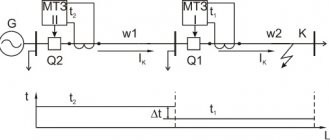
In the simplest case, the logic of the action looks like this: the protection of the connection, in parallel with the action of opening the circuit breaker, starts a time relay (breaker failure time delay). After time has passed, a command is generated to turn off adjacent switches.
A malfunction in the protection of any connection or an error by the maintenance personnel (for example, the “Start Breaker Failure Failure” key is not displayed, when the “Disconnection of the circuit breaker” key is displayed) can lead to a false operation. To reduce the risk of false operation, additional controls are used in the breaker failure protection circuits, as well as the action of the breaker failure itself. Controls:
- monitoring the presence of current in the switch;
- monitoring the presence of damage by reducing voltage and the appearance of negative and zero sequence voltages;
Selecting parameters [edit]
The delay for breaker failure protection is selected to exclude the action of the breaker failure during normal tripping of the circuit breaker [2]
$ t_ $ — breaker failure response time;
$ t_ $ is the return time of the protection that triggers the breaker failure. If there are several protections, the maximum time is selected;
$ t_ $ — maximum error of the breaker failure time relay in the direction of accelerating action;
$ t_ $ — reserve time (adjustment for unaccounted factors and errors).
The response time of the breaker failure failure is usually taken in the range of 0.25 - 0.40 s.
The current relay setting is assumed to be 10% of the rated current of the current transformer. This allows you to tune out the idle current of the connection, and also guarantees sensitivity during a short circuit.
Implementation [edit]
According to the principle of implementation of the breaker failure protection function, the following types are distinguished:
- centralized breaker protection system;
- individual level.
Centralized breaker level [edit]
All connections of one section are protected by the same external time relay. After time has passed, the relay acts to disconnect adjacent connections.
A centralized breaker failure failure is more preferable in primary circuits with bus systems with automatic fixation of connections, as it allows to reduce the number of connections between devices.
Individual level [edit]
It became widespread with the development of MP RZA. In this case, the breaker failure failure time delay is set in each protection terminal. The terminal protection functions, according to internal logic, trigger the breaker failure time delay. After time has passed, the protection terminal acts to disconnect adjacent connections.
How to connect AV according to the diagram
We offer schematic examples of connecting AV in a distribution panel.
Please note that each circuit diagram for connecting machines in the panel involves division into groups according to the selectivity of supply. Modular devices are divided into socket groups and lighting lines; sometimes protection for particularly powerful consumers is provided separately. Ideally, for safety and beauty, I install plugs on the sides of the bus so that the contacts are covered with insulation. Limiters on a DIN rail will help to visually separate groups of machines and ensure heat dissipation, since the devices heat up during operation and close proximity, and the limiters will also reliably fix the devices themselves. A separate group, as a rule, is isolated with a comb and only one AB from the group is supplied with power.
How to secure the module more conveniently
If in the future the network will expand and the number of AVs will correspondingly grow, we recommend attaching the protection to the DIN rail with two movable latches instead of one. Why is that? Because when replacing a device on one latch, you will need to completely disassemble the shield. Automatic machines with a pair of movable latches solve this problem in favor of quick and simple installation/dismantling. You will need a few minutes of time and a screwdriver.
Breakdown level and dynamic stability [edit]
Calculations for dynamic stability are performed taking into account the failure of the circuit breaker. Accordingly, to determine the estimated duration of the short circuit, the time of the breaker failure is taken into account.
$ t_ $ — estimated short circuit duration;
$ t_ $ — response time of high-speed protections (0.02-0.10 s);
$ t_ $ is the response time of the output relays (
$ t_ $ — breaker failure response time (0.25-0.40 s);
$ t_ $ is the response time of the output relays (
$ t_ $ — total shutdown time of adjacent switches (0.02 - 0.08 s);
This formula does not take into account various errors (there is no additional reserve time to take into account errors), therefore, in calculations for dynamic stability, a time reserve should be made.
How to avoid major wiring mistakes
It is very important to connect the circuit breakers in the panel yourself with an understanding of the functioning of the wires. How to avoid the most common mistakes for reliable contacts? Let's start in order.
- To get high-quality contact, you need to strip the core, that is, remove part of the insulation from the wire. If the insulation is not sufficiently stripped, it will fall under the contact clamp, and this can lead to melting of the wiring, the protection device itself, and even a risk of fire. Monitor and check the degree of tightening of the conductor in the socket.
- Wires of unequal cross-sections cannot be connected to the same terminal. The comb bus does an excellent job of connecting a group of machines to one power wire. But when an electrician prefers a homemade jumper made from cable cores, a safe result will only be achieved when using wires of the same cross-section. Otherwise, when the contacts are tightened, the clamp will be uneven (the thin core will be compressed worse, which will lead to loosening of the contact, heating, sparking and melting of the insulation), in addition, the machine platform will be deformed towards a smaller cross-section.
- If you connect a cable with a monolithic core to the machine, bend its end with a hook. This activity can be called creating a U-shaped bend and thanks to this simple step you will increase the area of contact of the wire with the surface of the clamp. This is an additional plus to the reliability of contacts.
- When connecting a multi-core flexible wire, it must be terminated before connecting to the AB. We recommend using NShVI (insulated pin sleeve lugs) or NShV lugs for termination. Double NShVI-2 is used to connect a pair of stranded wires; this is a convenient way to form jumpers for groups of circuit breakers.
- We strongly do not recommend soldering or tinning the ends of multi-core wires, since this is a sure way to “spreading” of the connection over time, overheating and melting of the solder, weakening and burnout of the contact.
Defining a section using a ruler
An economical and accurate method is to determine the cross-section of cables and wires using an ordinary ruler. In addition to this, you will need a simple pencil and the wire itself. To do this, the wire core is stripped of insulation and then tightly wound onto a pencil. After this, the total length of the winding is measured using a ruler.
The resulting measurement result must be divided by the number of turns. The result is the diameter of the wire, which will be needed for subsequent calculations. The cable cross-section is determined by the previous formula. To obtain more accurate results, there should be as many wound turns as possible, but not less than 15.
A significant disadvantage of this method is the ability to measure only relatively thin conductors. This is explained by the difficulties that arise when winding a thick cable. In addition, it is required to purchase a sample of the product in advance to perform preliminary measurements.