Inductor reactance
When alternating current flows I
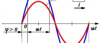
in a coil, a magnetic field creates an EMF in its turns, which prevents the current from changing. When the current increases, the EMF is negative and prevents the current from increasing; when it decreases, it is positive and prevents its decrease, thus resisting the change in current throughout the entire period.
U is formed at the terminals of the inductor in antiphase
, suppressing EMF, equal to it in amplitude and opposite in sign.
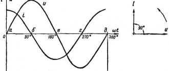
When the current passes through zero, the amplitude of the EMF reaches its maximum value, which forms a discrepancy in time between the current and voltage of 1/4 of the period.
U is applied to the terminals of the inductor
, the current cannot start instantly due to the counter-emf equal to
-U
, therefore the current in the inductance will always lag behind the voltage by an angle of 90°. The shift at the lagging current is called positive.
Let us write down the expression for the instantaneous voltage value u
based on the emf (
ε
), which is proportional to the inductance
L
and the rate of change of current:
u = -ε = L(di/dt)
. From here we express the sinusoidal current.
Integral of the function sin(t)
will be
-cos(t)
or an equal function
sin(t-π/2)
.
The differential dt
of the function
sin(ωt)
will leave the sign of the integral by the factor 1
/ω
.
As a result, we obtain an expression for the instantaneous value of the current with a shift from the voltage function by an angle π/2
(90°).
In this case, for the root-mean-square values of U
and
I,
As a result, we have a dependence of sinusoidal current on voltage according to Ohm’s Law, where in the denominator instead of R
expression
ωL
, which is the reactance:
The reactance of inductances is called inductive.
To main§ 59. The concept of stress resonance
In an alternating current circuit with active, inductive and capacitive resistances connected in series (Fig. 62, a), voltage resonance may occur.
At resonance, the voltages at the terminals of the inductive and capacitive reactances can become significantly greater than the voltage at the terminals of the circuit. Voltage resonance occurs if the inductive reactance XL
and capacitance
Xc
are equal to each other, i.e.
Let us assume that by selecting inductance and capacitance or changing the frequency a condition has been created under which XL
=
Xc
When the circuit is not tuned to resonance, then its total resistance
and in the circuit under consideration at resonance (when XL
=
Xc
) its total resistance
Thus, the total resistance of the circuit at resonance turns out to be equal to the active resistance. Reducing the total resistance of the circuit leads to the fact that the current strength in it increases. The voltage of the alternating current generator included in the circuit is spent on active resistance
Ua = I r
.
The voltage across the inductance is determined, according to Ohm's law, by the product of the current strength and the amount of inductive reactance. Since the current in the circuit has increased, the voltage UL = I XL
has increased.
The voltage across the capacitance is also determined by the product of the current and the value of capacitance. Therefore, the voltage across the capacitance Uc = I Xc
.
Due to the fact that the same current flows in series-connected resistances and at resonance the inductive reactance XL
is equal to the capacitive reactance
Xc
, the voltage across the inductance and the voltage across the capacitance are equal:
UL = Uc
or
I XL = I Xc
If both reactances XL
and
Xc
, without violating the resonance conditions
XL
=
Xc
, then both partial voltages
UL
and
Xc
, and the current strength in the circuit will not change.
In this way, it is possible to obtain UL
and
Uc
many times greater than the voltage
U
at the circuit terminals. Let's construct a vector diagram (Fig. 62, b) for the circuit under consideration at voltage resonance. Let us plot the current vector horizontally on the selected scale. In active resistance, current and voltage are in phase. Therefore, we will plot the voltage vector along the current vector. Since the voltage across the inductance leads the current by 90°, we will move the vector upward at an angle of 90°. The voltage across the capacitor lags the current by 90°, so the vector equal to the vector will be laid down at an angle of 90° to the current vector. The vector diagram shows that the voltage across the inductance and the voltage across the capacitor are equal and out of phase with each other by 180° and are mutually compensated. The phase angle between current and voltage at resonance is zero. This means that the current and voltage are in phase (as in a circuit with active resistance).
Example.
The AC circuit includes in series an active resistance
of r
= 5
ohms
, an inductance of
L
= 0.005
H
and a capacitance of 63.5
μF
.
A generator connected to the circuit produces an alternating voltage U
= 2.5
V
with a resonant frequency
f
= 285
Hz
. Determine the inductive and capacitive reactance, the total resistance of the circuit, the current flowing in the circuit, the voltage across the capacitance and inductance. Solution. Inductive reactance
XL = 2π f L
= 2 · 3,14 · 285 · 0,005 = 8,9
ohm
,
Capacitance
Inductive reactance is equal to capacitive reactance and, therefore, voltage resonance occurs in the circuit. Circuit impedance at resonance
Current strength in the circuit
Inductor voltage
UL=I XL
= 0.38 8.9 = 7.4
V
Capacitance voltage
Uc = I Xc
= 0.38 · 8.9 = 7.4
V
As can be seen from the example given, the voltages on the inductance and capacitance are equal to and exceed the generator voltage.
Previous page
| table of contents | Next page |
Lecture for a college in electrical engineering on the topic “Resonance in an AC circuit.”
Lecture 8.
Circuit with active resistance, inductance and capacitance.
Resonant mode of operation of the circuit. Voltage resonance. Resonance of currents. Power factor. A circuit with active resistance, inductance and capacitance.
A circuit with active resistance, inductance and capacitance represents a common
the case of a series connection of active and reactive resistances is
series oscillatory circuit.
Rice.
a) A circuit with a resistor, an inductor and a capacitor, b) A vector diagram of the circuit, c) a triangle of circuit resistances R, X L and X C
We take the current phase to be zero: i
= I m sin
* t;
Then u R =
U m sin
* t;
u L = U m sin (
* t + /2);
u C = U m sin (
* t - /2)
Let's build a vector diagram for ХL>ХС, that is, UL= I ХL> UC= I ХC
The resulting voltage vector U closes the polygon of vectors UR, UL and UC. The UL+UC vector determines the voltage across the inductance and capacitance. As can be seen from the diagram, this voltage can be less than the voltage in each of the sections separately. This is explained by the process of energy exchange between inductance and capacitance.
Since the modulus of the vector UL+UC is calculated as the difference between the effective values UL—UC, then
and therefore
Ohm's law for this circuit in this case,
where Z is the total resistance of the circuit.
The difference between inductive and capacitive reactance XL—XC=X is called
reactance of the circuit.
When XL>XC the reactance is positive and the circuit resistance is active-inductive in nature. In this case, the phase shift angle φ>0 is positive.
With XLC, the reactance is negative and the circuit resistance is active-capacitive in nature. In this case, the phase shift angle φ<0 is negative.
Resonant mode of operation of the circuit.
The resonant mode of operation is a mode in which the resistance is purely active. In relation to the power source, the circuit elements behave in resonant mode as an active resistance, so the current and voltage in the unbranched part are in phase. The reactive power of the circuit is equal to zero.
A distinction is made between voltage resonance and current resonance.
Voltage resonance.
Voltage resonance occurs in a series oscillating circuit circuit when the current in the circuit coincides with the phase voltage φ = 0°.
a) b) c)
Rice. a) Series resonant circuit, b) Vector diagram of the circuit at X L =X C , c) resonant curve of the series circuit.
The reactance of the series circuit is zero X=0
at
X L =X C .
Since X L
=
L
; X c = 1/
C ;
= 2
f then
Resonant frequency With voltage resonance, the source frequency is equal to the natural frequency of the circuit.
Voltage resonance condition:
a) circuit resistance Z = R
minimal and purely active;
b) the circuit current is in phase with the source voltage and reaches its maximum value;
c) the voltage on the inductive coil is equal to the voltage on the capacitor and each individually can be many times higher than the voltage at the circuit terminals.
The quantity is called the characteristic impedance of the circuit.
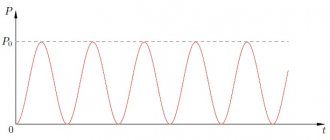
The resonance curve shows the dependence of the effective value of the current in the circuit on the source frequency at a constant natural frequency of the circuit.
Let's place the dependence of inductive and capacitive reactance on the source frequency on one graph.
Rice. Dependence of reactance X on source frequency.
At frequencies close to f
0, the reactance is small and the loop current is large.
Voltage resonance is widely used in radio engineering and electronics to isolate
signals of a given frequency.
Resonance of currents.
Resonance of currents occurs in an unbranched section of the circuit of a parallel oscillating circuit when the current coincides with the voltage in phase φ = 0°.
a) b)
Rice. a) Parallel oscillatory circuit, b) Vector diagram with current resonance.
If IR is small, then Ic = ILP
Current resonance condition:
a) circuit impedance Z is maximum and fully active,
b) the current in the unbranched part of the circuit is in phase with the voltage and is very small,
c) the reactive component of the current in the coil is equal to the reactive component of the current in the capacitor.
In order for the current I
in the unbranched part of the circuit is in phase with the voltage,
reactive component of the current of the inductive branch I
Lp must be equal in magnitude to current
capacitive branch I
C.
The active component of the current in the inductive branch I
La turns out to be
equal to the source current I
.
Let's determine the circuit resistance under the assumption R
<<
X
L.
Let us formulate the signs of current resonance:
a) circuit resistance Zk is maximum and purely active;
b) the current in the unbranched part of the circuit is in phase with the source voltage and
reaches almost a minimum value;
c) the reactive component of the current in the coil is equal to the capacitive current, and these currents
can be many times higher than the source current.
Power factor.
By analogy with the resistance triangle, for a series connection of a resistor, inductor and capacitor, you can obtain a triangle of voltages and powers.
Rice. Resistance triangle and impedance calculation
Rice. Power triangle and total power calculation
Active power developed by the generator in nominal mode P = I nom
U nom cos φ
Full use of the generator power occurs at cos
φ = 1
.
In this case, the active power is maximum and equal to the rated apparent power S nom = I nom U nom
A real AC electrical circuit necessarily contains reactance. This increases heating losses.
Cos
φ is called the power factor.
cos
φ = P / S is the ratio of active power to apparent power.
It shows how much of the electrical energy produced by an AC source is used to perform useful work.
A decrease in cos
φ
leads to an increase in heat losses in the transmission line, which grow in inverse proportion to the square of the power factor.
To fully utilize the rated power of generators and reduce heat losses, it is necessary to increase the cos φ
of energy receivers to values close to unity (0.95-1.0).
To increase cos
φ,
capacitor banks are connected in parallel to the energy receiver.
Thanks to this, the capacitance and line become the source of reactive energy for the receiver
transmission is unloaded from reactive current.
In practice, receivers with satisfactory cos
φ
include asynchronous motors as industrial drives.
cos φ
value ranges from 0.1-0.3 at idle and 0.8-0.85 at rated load.
Vector circuit diagrams for xl xc
Construction of a vector diagram
For serial connection circuits, the following vectors are plotted on the diagrams:
1) Current strength I - - it is the only one, because the currents through the sections of the circuit are equal
2) Voltages (voltage drops in sections) - there are four of them according to the number of connected elements.
According to the theory, there is no phase shift in active resistance between the voltage vector and the current vector, therefore the vectors of these quantities coincide in direction (angle) figure (a)
UR
On inductive reactance, the voltage vector and current vector are shifted by , and the voltage leads the current (Figure b), and on capacitive resistance, the voltage lags behind the current by the same angle. Minus indicates the opposite nature of the shift (Figure c)
| Fig.b) | Fig c) |
Taking into account the above, if you place the current vector (a segment of a certain length on an accepted scale) horizontally, then the voltage vectors in the sections according to the diagram will be located as in the diagrams shown without scale
Diagram 1. - inductive reactance is greater than capacitive reactance
UI
Diagram 2 - inductive reactance is less than capacitive reactance
The voltage vector U at the circuit terminals is constructed based on Kirchhoff’s second law as the sum of vectors
Stress values in areas. determined by Ohm's law. And then using the scale we find the lengths of the vectors
,
For example U=60V, we take the scale M and =
10V/cm, then the vector length
lu
=60/10=6cm
Draw conclusions about the work done.
TASK FOR CALCULATION AND GRAPHIC WORK
Unbranched AC circuit.
Active resistance R, inductance L and capacitance C are connected in series and connected to a source with voltage U. The initial data is given in Table 1. Draw an electrical circuit, determine the total resistance of the circuit Z and the power factor COSj, current I , voltage, circuit power P, QL,QC, S.
Construct a vector diagram to scale, resistance and power triangles.
Calculated data for each option (last digit of the grade book) are given in Table 1.
Table 1. Initial data
| Option No. | R, Ohm | XL, Ohm | XC, Ohm | U, V |
To explain the methodology for calculating an unbranched AC circuit, guidelines and an example are given.
METHODOLOGICAL INSTRUCTIONS FOR SOLVING THE TASK
1. Vector diagram of current and voltage. If a sinusoidal current i=ImSINjt flows in an unbranched circuit with active resistance R, inductance L and capacitance C (Figure 1), then the instantaneous value of the voltage applied to the circuit is u=ua+uL+uc. The voltage across the active resistance Ua is in phase with the current in circuit I, the voltage across the inductance UL leads the current by 90°, and the voltage across the capacitance UC lags the current by 90°.
Effective voltage values in circuit sections: Ua=IR; UL=IXL; UC=IXC. The effective value of the voltage at the circuit terminals is obtained by the vector addition method: U=Ua+UL+UC . Let's construct a vector diagram of current and voltage. First, let's plot the current vector I (Figure 2). The voltage drop vector in the active resistance Ua is in phase with the current vector I , the inductive drop vector UL is set up at an angle of 90 0, and the capacitive voltage drop vector UC is set down at an angle of 90 0 to the current vector I. By adding the voltage vectors Ua, UL, UC , we obtain the voltage vector U applied to the entire circuit. The vector diagram is constructed for the case when XL>XC and the circuit is active-inductive in nature.
Under this condition, UL>UC, and the voltage U leads the current I in phase by an angle j. If XC>XL, then UC>UL and the circuit has an active-capacitive character. In this case, the voltage U (Fig. 2) lags in phase from the current I by angle j. If the reactances are equal (XL=XC) UL=UC (Figure 32). In this case, the voltage U is in phase with the current I (j=0) and the circuit is active.
This mode in the circuit under consideration is called voltage resonance .
2. Resistance and power triangles. Consider the stress triangle in (Figure 4a). One leg of this triangle expresses the active voltage Ua, the other - the reactive voltage of the circuit UL-UC, and the hypotenuse - the total voltage U. Dividing the sides of the voltage triangle by the current I, we obtain a resistance triangle (Figure 4b), from which it follows that the total resistance of the circuit is equal to :
Ohm's law and the relationship between R, I and U
- home
- electrical and Electronics
- Ohm's law
First, let's look at the definitions of basic electrical quantities, then consider the laws that connect these quantities with each other based on formulas and graphical dependencies.
This is how this article will develop from simple to complex. The first thing to note is that there are DC and AC circuits. The difference between them is in the nature of the flow of electrical quantities - in alternating current circuits, current and voltage change over time according to a certain law (for example, a sine wave). In DC circuits, the value remains constant over time.
In both the first and second circuits, the main quantities will be: current, voltage and resistance.
Electricity
- the ordered movement of charged particles (electrons) through a conductor (conducting medium) from a point with a high potential to a point with a lower potential. It is commonly said that current flows from plus to minus in DC circuits. It is measured in amperes, designated “i”.
Electrical resistance
characterizes the ability to limit the value of electric current. It is measured in ohms and denoted by r. The reciprocal of resistance is conductivity. Depending on the value of resistance, materials are classified into: conductors, dielectrics and insulators.
Electrical voltage
equals the potential difference between two points. U=f1-f2. It is logical that voltage can be both positive and negative. The unit of measurement is volts (V).
The relationship between these quantities is described by Ohm's law:
The value of current in an electrical circuit is directly proportional to the voltage and inversely proportional to resistance. I=U/R - this formula is applicable for a direct current circuit. Knowing two quantities, we can always find the third.
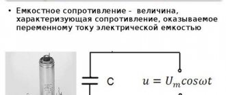
For alternating current, the formula takes the form I=U/Z, where Z is the total resistance of the circuit, which consists of active, capacitive and inductive components:
- R
- active resistance (ohmic) - XL
- inductive reactance (inherent in coils, windings, TG stator) - prevents the flow of current - XC
- capacitance (capacitor, found near the cable) - prevents the flow of voltage - Z
- reactance (impedance, total resistance) consists of two components: active (R) and reactive (X). And reactive (X) already consists of inductive (XL) and capacitive (XC)
Graphically, the relationship between resistances can be displayed in the form of a right triangle (vector representation).
In alternating current circuits, current and voltage values change over time according to a certain law. For example, for a sinusoid:
I=Im*sin(wt+f)
In this formula, I is the instantaneous current value, Im is the amplitude value.
Amplitude
- the maximum value, amplitude, that the value takes over a period. In the formulas above, these are the values with the index “m” - such as the maximum.
Instant
— the value of a quantity at a given time. The maximum of the instantaneous values is amplitude.
Current
- such a value of alternating current at which, over a period, as much heat would be released in the resistor as in a direct current circuit. These are the values shown by our voltmeters and ammeters. For a sinusoid, the effective is equal to 0.707 of the amplitude. 1/root(2)=0.707.
How to calculate a shunt for an ammeter
How to connect an ammeter?
Depending on the predominance of a certain type of resistance, the current and voltage vectors will be shifted relative to each other:
Purely active resistance - current and voltage are in phase.
The inductive one predominates - which means, as stated above, it is more difficult for the current to pass through and it lags behind the voltage.
The capacitive component predominates - the current goes into isolation, the voltage is inhibited by the capacitance.
Also, AC circuits can be single-phase or three-phase. In three-phase circuits, the phase designations used are: phase A (yellow, U), phase B (green, V) and phase C (red, W). As they recently said at one railway site: phase “A” is going to Minsk. 
The phases can be connected to each other in various patterns: star, triangle, zigzag and other rarer ones.
What is Neutral Bias Voltage?
Units for measuring current, voltage, resistance and other electrical quantities