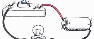
Many people know that in addition to voltage, an electrical outlet also contains current, which is dangerous to human life. But how to measure it? How difficult is it to do? To measure current there is a special device called an ammeter.
So, an ammeter is an electrical measuring instrument designed to measure current in an electrical circuit. Electric current is the directional movement of charged particles (electrons), it is measured in Amperes and, accordingly, the device that measures it is called an ammeter.
An ideal ammeter has zero internal resistance. Well, where have you seen something ideal in our world? Therefore, even in a real ammeter, the internal resistance, although minimal, is still not zero. Like a voltmeter, an ammeter can also have a measurement range (for example, 1, 2, 3, 5, 10 A), which depends on the internal resistance of the electrical measuring instrument. As a rule, the additional resistance is already installed in the device body and is switched using a special switch.
What internal resistance should the ammeter have?
In order for the ammeter not to noticeably change the total resistance of the circuit, its own resistance, as follows from formula (54.2), must be small compared to the resistance of the circuit. Therefore, ammeters are made with very low resistance (a few tenths or hundredths of an Ohm).
Interesting materials:
Is it possible to change seats on the train? Is it possible to replace interior doors without damaging the wallpaper? Is it possible to change the modem on iPhone 7? Is it possible to change the password for government services? Is it possible to enter the territory of Peterhof? Is it possible to get to Vyborg? Is it possible to visit the pyramids in Egypt? Is it possible to go to graduate school after residency? Is it possible to view a private profile on Facebook? Is it possible to enroll on a budget with a higher education?
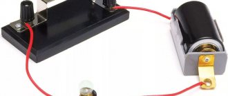
Why is the ammeter always connected in series?
The ammeter ALWAYS connected to the electrical circuit being measured in series. All "directionally moving" electrons pass through the measuring device. But what about power losses, you ask? Yes, in this case it is inevitable, but it should be remembered that the ammeter has minimal internal resistance, and accordingly the power losses in it will be insignificant.
The ammeter resistance should be minimal for two reasons:
- All measured current passes through the ammeter.
- The ammeter should have minimal impact on the electrical circuit to which it is connected.
What is the difference between a voltmeter and an ammeter?
Ampere is a unit of measurement of electric current. Therefore, an ammeter measures the current in an electrical circuit. A volt is a unit of measurement of electromotive force and voltage in an electrical circuit. Naturally, using a voltmeter you can get readings of the voltage of an electric current.
Interesting materials:
Where do bees put pollen? Where are sick leave transferred? Where to change the clocks in the fall? Where to file an application for review based on newly discovered circumstances? Where to file a consumer protection claim? Where should a claim for alimony be filed? Where to apply for alimony without divorce? Where to apply for alimony? Where to file a claim for division of property? Where to apply to become a labor veteran?
What happens if a voltmeter is connected in series?
Nothing will happen. The voltmeter has a high internal resistance, so it will measure the emf of the source. It is much more interesting to connect the ammeter to the source in parallel with the load! Smokes beautifully!
An ideal voltmeter has an infinitely high resistance, therefore no current will flow through the circuit - the voltmeter will simply show the source EMF (if there is an EMF source in the circuit)
Nothing will happen. The voltmeter has a high internal resistance, so a device in whose circuit it is connected in series most likely simply will not work.
Nothing. That is, if you have to break the circuit to do this, further connecting the voltmeter is essentially connecting to the places where the circuit breaks. great resistance. The voltmeter must have a huge resistance, so ideally its connection should not affect the circuit itself. Connect it between the points between which the potential difference (voltage) should be measured... In principle, it doesn’t matter how you connect it.
The question is clearly a practical one. Well, where in practice can I get an ideal voltmeter? And therefore it (the voltmeter) will show that part of the voltage that remains on it. This, in turn, depends on the load resistance with which the voltmeter is connected in series, and the internal resistance of the voltmeter itself. For example, the load resistance is 100 Ohms, the voltmeter is 1 kOhm. That is, the voltmeter will show 1/1.1 of the voltage at the input of the circuit. And if we also take into account the internal resistance of the current source... That's a little less 
The voltmeter will show the voltage on itself.
touch.otvet.mail.ru
Connecting a voltmeter
The voltage at the power source or circuit element is measured by a device that is connected in parallel with the device.
The coil of the device has low resistance, and when connected directly to the network, the current will be large. To reduce current consumption and the effect on the electrical network, additional resistances are connected in series with the device.
Important! When the voltmeter is connected in series with the load, it will show the voltage of the power source with an error due to the load resistance. An ammeter is connected in series.
Constant pressure
Methods for measuring DC voltage depend on its magnitude:
- up to 1 millivolt – digital and analog devices with a built-in amplifier;
- up to 1000 volts use conventional devices of various systems;
- above 1 kV, measurements are made with electrostatic devices designed for operation in high-voltage networks or conventional ones connected through a divider.
The measurement limit is increased by connecting in series with the additional resistance device Rext. To increase the limit by n times, the total resistance must also be increased by n times and, taking into account the resistance of the device Rpr, Rext=Rpr*(n-1). The scale readings are also multiplied by n.
AC voltage
Methods and types of devices for measuring in alternating current networks depend on the voltage and frequency of the network:
- up to 1 volt – digital and analog devices with amplifiers;
- up to 1 kV and frequency up to tens of kHz – rectifier systems, electromagnetic, electrodynamic devices;
- at frequencies up to tens of megahertz - thermoelectric and electrostatic devices.
Important! An AC voltmeter shows the actual voltage value. With a sinusoidal shape, its value is √3 (1.7) less than the amplitude.
Extension of the measurement limits is carried out by switching on through an isolating or autotransformer, as well as by using additional resistance. Its value is calculated similarly to measurements in a DC network.
When using an isolation transformer, the device readings are multiplied by the transformation ratio n=U1/U2.
The voltmeter must be connected according to certain diagrams. This is done to ensure that the device readings correspond to the network parameters.
Connecting a voltmeter
A voltmeter measures voltage - the potential difference between two points in an electrical circuit.
Since the tension is between two
points, then the voltmeter is connected
in parallel to
the power source or some circuit element.
No matter how strange or funny it may sound, it is impossible to connect a voltmeter into a circuit in series, because the voltage cannot be measured at one point
- two points are required.
As is known, direct current
does not change its direction over time, which means that the voltage and polarity of the direct current source also do not change.
Therefore, when measuring DC voltage, polarity must be observed.
– the plus of the voltmeter is to the plus of the circuit, and the minus to the minus. If the polarity is reversed, the needle will deviate in the opposite direction (towards zero, beyond the scale). Usually this does not lead to dire consequences and when the device is disconnected from the circuit, the arrow will return to its original position, but in some cases this can damage the device.
Why is the voltmeter in parallel and the ammeter in series?
To measure small currents and voltages, a highly sensitive galvanometer is used - this is the basis and prototype of any pointer measuring instruments. If you connect an additional resistance in series with a galvanometer, you get a voltmeter, and if you connect a shunt in parallel, you get an ammeter.
Despite the fact that digital meters have become very widespread in recent decades, there are still areas of application in which the advantages of pointer instruments are needed, for example, for observing the dynamics of a changing quantity during some transient processes, for measuring changing signals, and so on.
In this article we will talk about connecting voltmeters and ammeters to measure voltages and currents.
How is a voltmeter connected to a circuit and why?
Voltmeter
, how the measuring instrument is connected in parallel with the load or source in relation to which you want to measure the voltage value.
This is done because the voltmeter
represents a fairly large resistance; in electrical examples it is taken to be infinity.
Interesting materials:
Why isn't my music playing on Apple Music? Why won't my music purchased from iTunes load? Why won't music load into apple music? Why won't music load into Apple Music? Why can't you listen to music on headphones? Why does music make people cry? Why do music give me goosebumps? Why won't music load into iTunes? How many hours of music in 4 GB? How many minutes of music can fit on a CD?
Why is the voltmeter connected in parallel when measuring voltage?
Correct answer: b) in parallel. The voltmeter coil has a high resistance, so it is connected to the circuit only parallel to the load, otherwise this will affect the accuracy of the device readings. The ammeter, on the contrary, is connected in series to the circuit.
Interesting materials:
How to create a third account on Instagram? How to create a second WhatsApp account? How to create a private session in GTA Online? How was the Red Book created? How to spam laughter in Dota? How to save the forest? How to save tasteless borscht? How to save eye shadow without alcohol? How to save a dried rose in a pot? How to Speedrun in HL 2?
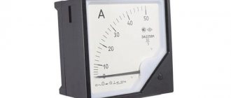
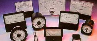
Types of ammeters
The classification of ammeters depends on their design and the type of current flowing through it. Below are the types of electrical measuring instruments with respect to design.
- Ammeter of magnetoelectric system with permanent magnet.
- Electromagnetic ammeter.
- Electrodynamic ammeter.
- Ammeter with bridge rectifier.
According to the type of current, ammeters are divided into:
- DC ammeters;
- AC ammeters;
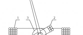
Permanent magnet moving coil (PMMC) magnetoelectric ammeter
The magnetoelectric principle underlies the operation of such a device. In short, the essence of its work is as follows: the coil of the measuring device is placed in a constant magnetic field. When current flows through the coil, a torque will be created, which will turn the arrow of the device.
Electrodynamic ammeter
It is used to measure both AC and DC current. The accuracy of the device is quite high compared to a magnetoelectric measuring device. The calibration of the device is the same for both alternating and direct current, that is, if the ammeter was calibrated for direct current, then it can be used to measure alternating current without recalibration.
Detector system ammeter (with bridge rectifier)
Used to measure alternating current. The devices use a bridge rectifier that converts alternating current into direct current, which is measured using a magnetoelectric ammeter. This type of device is used to measure current in control circuits and when using current transformers.
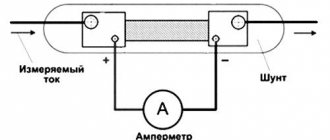
Measuring shunt
Excessive currents that can flow in powerful power circuits will damage the measuring device when connected directly. To avoid this, use a measuring shunt.
The shunt has a very low active resistance, which has minimal effect on the measured circuit. In parallel, an ammeter is connected to it, which already measures the current.