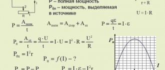
Electrical capacity
Electrical capacity of a flat capacitor
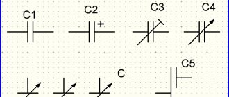
This term characterizes the storage capacity of a passive element. The designations of serial products indicate the nominal value. Since the base unit (F, farad) is too large, diminutive prefixes are used to designate commonly used electronic components:
- millifarad (mF) – 10-3 F;
- nanofarad (nF) – 10-9 F;
- picofarad (pF) – 10-12 F.
One farad corresponds to the capacitance at which the accumulated unit charge (1 C) will create a potential difference across the plates of 1 V.
Capacitor. The design and principle of operation of a capacitor.
1 electrodes made of microporous graphite, 2 electrolyte. The effective area of the plates of such capacitors, due to porosity, reaches up to 10,000 m2 per gram of electrode mass, which makes it possible to achieve a very large capacity with very small capacitor sizes. Currently, ultracapacitors are produced for voltages up to 2.7 V and capacities up to 3 kF. Their specific storage capacity usually ranges from 0.5 Wh/kg to 50 Wh/kg, and there are prototypes with a specific storage capacity of up to 300 Wh/kg. The manufacturing technology of ultracapacitors
is very complex, and the cost per unit of energy stored in them is therefore much higher than that of other capacitors, reaching up to 50,000?/kWh. Despite this, due to their simplicity of design, small size, reliability, high efficiency (95% or more) and durability (several million charge-discharge cycles), they began to be used both in vehicles and in industrial power plants instead of electrochemical batteries and other means of energy storage. They are especially beneficial when energy is consumed in the form of short pulses (for example, to power the starter of internal combustion engines) or when fast (seconds) charging of the storage device is required. For example, in 2005, trial operation of ultra-capacitor buses began in Shanghai, the battery of capacitors of which is charged while the bus is parked at each stop. The oldest capacitor and at the same time the oldest accumulator of electrical energy can be considered amber objects, the electrification of which when rubbed with woolen cloth was discovered by the Greek philosopher Thales in approximately 590 BC. X. He called this phenomenon electronic (from the Greek word electron, 'amber'). The first electrostatic generators, invented in the 17th century, were also spherical or cylindrical capacitors, on the surface of which an electric charge could accumulate sufficient to cause discharge phenomena. The first real capacitor is considered to be an amplifying flask, invented on October 11, 1745 during experiments on the electrification of water by an amateur physicist, dean of the Cammin Cathedral, Ewald Jurgen von Kleist (1700–1748) (Fig. 4) ;
Rice. 4. Capacitor by Ewald Jürgen von Kleist. 1 bottle filled with water, 2 nail, which together with water forms the top cover, 3 wire to the electrostatic generator, 4 metal plate (bottom cover). U voltage of this device can clearly distinguish between two plates and the dielectric between them. The first flat capacitor was made in 1747 by the London physician John Bevis (1693–1771), and the term capacitor itself (Italian condensatore, 'to thicken') was introduced in 1782 by Alessandro Volta, a professor of experimental physics at the University of Pavia (Pavia, Italy). Alessandro Volta, 1745–1827). The first electrolytic capacitors were developed in 1853 by the head of the Konigsberg Physiological Institute (Konigsberg, Germany), Hermann von Helmholtz (1821–1894), and the first ultracapacitor with porous graphite electrodes was submitted for patenting in 1954 by a researcher at the electrical engineering concern General Electric ( General Electric, USA) Howard I. Becker. Practical applications of ultracapacitors began to develop rapidly in the early years of the 21st century.
| Heat pump. Design and principle of operation of a heat pump |
| Fridge. The structure and principle of operation of the refrigerator. |
| Lead acid battery. The device and principle of operation of the battery. |
Field energy of a parallel plate capacitor
How to choose a capacitor
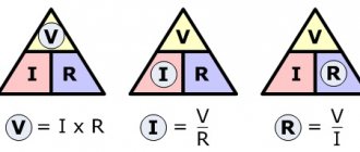
To simplify things, we can consider an example with moving oppositely charged plates. The generated attractive force ( F ) will be measured by the magnitude of the charge ( q ) and the field strength ( E ) between the corresponding plates:
F = q * E.
Since E = q /(2* e 0 * S ), it is easy to obtain an expression for the value of force interaction:
F = q2/(2*e0*S),
Where:
- e0 is the electrical constant = 8.854 * 10-12 F*m-1;
- S is the area of the plates.
Work (A) is equal to the product of force and distance traveled (d), so W (energy of a parallel-plate capacitor) = A = F * d = d *q2/(2*e0*S). Capacitance (C) is defined as C = d /(e0*S). The following transformations can be used to obtain the final expression:
- W = q2/(2*C);
- q = C * U;
- capacitor energy formula:
W = ½ *C * U2.
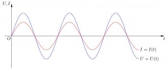
D.C
Gentlemen, hello everyone! Today we will talk about the energy of capacitors . Attention, now there will be a spoiler: a capacitor can accumulate energy. And sometimes very large. What? This is not a spoiler, was it already obvious to everyone? Great if so! Then let's go look into this in more detail!
In the last article, we came to the conclusion that a charged capacitor, disconnected from the voltage source, can itself produce some current for some time (until it discharges). For example, through some kind of resistor. According to the Joule-Lenz law, if current flows through a resistor, heat is generated across it. Heat means energy. And this same energy is taken from the capacitor - actually, there’s nowhere else. This means that some energy can be stored in the capacitor. So, the physics of the processes is more or less clear, so now let's talk about how to describe all this mathematically. Because it’s one thing to describe everything in words – it’s cool, wonderful, it should be, but in life you often need to calculate something and here ordinary words are not enough.
First, let's remember the definition of work from mechanics. The work
A of a force F is the product of this same force F and the displacement vector s.
I believe that you studied mechanics once and you know this. Scary vector symbols are only needed if the direction of the force does not coincide with the displacement: such as the case when the force pulls strictly straight, but the displacement is at some angle to the force. This happens, for example, when a load moves along an inclined plane. If the direction of the force and displacement coincide, then you can safely discard the vectors and simply multiply the force by the length of the path, thus obtaining work:
Let us now recall the article about Coulomb’s law. We got a wonderful formula there, which now is the time to remember:
That is, if we have an electric field with intensity E and we place a certain charge q in it, then this charge will be acted upon by a force F, which can be calculated using this formula.
No one is stopping us from substituting this formula into the formula written just above to work. And thus find the work that the field does when a charge
q moves in it over a distance s.
We will assume that we move our charge q exactly in the direction of the field lines. This allows you to use the formula for working without vectors:
Now, gentlemen, attention. I remind you of one important thing from the same mechanics. There is a special class of forces called potential.
To put it in simplified language, it is true for them that if this force did work A on some segment of the path, this means that at the beginning of this path the body on which the work was done had more energy for this same A, than at the end. That is, as much as you work, the potential energy changes by that much. The work of potential forces does not depend on the trajectory and is determined only by the starting and ending points. And on a closed path it is generally equal to zero. It is precisely the force of the electric field that belongs to this class of forces.
Here we place our charger q in the field. Under the influence of this field, it moves a certain distance from point C to point D. Let, for definiteness, at point D the charge energy be equal to 0. During this movement, the field does work A. It follows from this that at the beginning of the journey (at point C) our the charger had some energy W=A. That is, we can write
Now is the time to draw pictures. Let's take a look at Figure 1. This is a slightly simplified illustration of the physics of a parallel-plate capacitor. We looked at this more fully last time.
Figure 1 – Flat capacitor
Let's now bend our consciousness a little and look at our capacitor differently than before. Let's assume that we take, for example, a blue plate as a basis. It creates some field with some tension. Of course, the red plate also creates a field, but at the moment it is not interesting. Let's look at the red plate as some charge +q located in the field of the blue plate.
And now we will try to apply all of the above to the red plate as if it were not a plate at all, but just some charge +q. That's how clever it is. Why not? Perhaps you will say - how can this be? Previously, we always assumed that our charges were point charges, but here we have a whole large plate. Somehow she doesn’t quite hit the mark. Calm down, gentlemen. No one is stopping us from breaking the red plate into a huge pile of small particles, each of which can be considered a point charge Δq. Then you can apply all of the above without any problems. And if we carry out all the calculations of forces, tensions, energies and other things for these individual Δq and then add the results together, it turns out that we were so overzealous in vain - the result will be exactly the same as if we simply took the charge during the calculations +q. Anyone who wants can check it out, I’m all for it. However, we will immediately work according to a simplified scheme. I would just like to note that this is true for the case when our field is uniform and the charges are distributed evenly across all plates. In reality, this is not always the case, but such a simplification makes it possible to significantly simplify all calculations and avoid any gradients and integrals without significant harm to practice.
So, let's return to Figure 1. It shows that between the plates of the capacitor there is a field with some intensity E. But we have now agreed to separate the roles of the plates - the blue one is the source of the field, and the red one is the charge in the field. What kind of field does one blue lining create separately from the red one? What is its tension? Obviously, it is two times less than the total tension . Why is this so? Yes, because if we forget about our abstraction (such as a red plate - and not a plate at all, but just a charge), then both plates - both red and blue - make an equal contribution to the resulting tension E: each by E/2. As a result, the sum of these E/2 results in exactly the same E that we have in the picture. Thus (discarding vectors), we can write
Now let’s calculate, so to speak, the potential energy of the red plate in the field of the blue plate. We know the charge, we know the tension, we also know the distance between the plates. Therefore, we feel free to write down
Go ahead. In fact, no one bothers you to swap the red and blue linings. Let's think the other way around. We will now consider the red plate as a source of the field, and the blue plate as a certain charge –q in this field. I think even without making a calculation it will be obvious that the result will be exactly the same. That is, the energy of the red plate in the field of the blue plate is equal to the energy of the blue plate in the field of the red plate. And, as you may have already guessed, this is the energy of the capacitor.
Yes, using this very formula you can calculate the energy of a charged capacitor:
I hear people shouting to me: stop, stop, again you’re rubbing some kind of bullshit on me! Well, okay, I can somehow measure the distance between the plates. But for some reason they again force me to count the charge, which is not clear how to do it, and besides, I need to know the tension, but how can I measure it?! The multimeter doesn't seem to be able to do this! That's right, gentlemen, now we will do transformations that will allow you to measure the energy of a capacitor just using an ordinary multimeter.
Let's get the tension out of the way first. To do this, let us remember the wonderful formula that connects tension with tension:
Yes, the voltage between two points in a field is equal to the product of the strength of that field and the distance between those two points. So, substituting this most useful expression into the formula for energy, we get
It’s already easier, the tension is gone. But there is still a charge that is not clear how to measure. To get rid of it, let's remember the formula for capacitor capacity from the previous article:
Yes, for those who have forgotten, I remind you that capacitance is defined as the ratio of this ill-fated charge accumulated by the capacitor to the voltage across the capacitor. Let's express the charge q from this formula and substitute it into the formula for the energy of the capacitor. We get
Now this is a useful formula for the energy of a charged capacitor! If we need to find out what energy is stored in a capacitor with a capacitance C charged to a voltage U, we can easily do this using this formula. Capacitance C is usually written on the capacitor itself or on its packaging, and the voltage can always be measured with a multimeter. From the formula it can be seen that the greater the energy in the capacitor, the greater the capacitance of the capacitor itself and the voltage across it. Moreover, the energy grows in direct proportion to the square of the voltage. This is important to remember. Increasing the voltage will lead to an increase in the energy stored in the capacitor much faster than increasing its capacitance.
For special charge lovers, you can use the formula for determining capacitance to express not the charge, but the voltage and substitute it into the formula for the energy of the capacitor. Thus, we obtain another energy formula
This formula is used quite rarely, and in practice I don’t remember at all that I would calculate anything using it, but since it exists, then the path will also be there to complete the picture. The most popular formula is the average one.
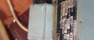
Let's do some calculations for fun. Let us have a capacitor like this
Figure 2 – Capacitor
And let us charge it to a voltage of, say, 8000 V. What energy will be stored in such a capacitor? As we can see from the photograph, the capacitance of this capacitor is 130 μF. Now it's easy to perform energy calculations:
Is it a lot or a little? Certainly not a little! Not even very little! Let's just say that the permitted energy of stun guns is some funny units of joules, but here there are thousands of them! Taking into account the high voltage (8 kV), we can safely say that for a person, contact with such a charged capacitor will most likely end very, very sadly. Particular care must be taken at high voltages and energies! We had a case where a short circuit occurred in several of these capacitors, connected in parallel and charged up to several kilovolts. Gentlemen, this was not a sight for the faint of heart! It boomed so loudly that my ears were ringing for half a day! And copper from melted wires settled on the walls of the laboratory! I hasten to reassure you that no one was hurt, but this was a good reason to further think about ways to remove such gigantic energy in case of emergency situations.
In addition, gentlemen, it is important to always remember that the capacitors of the power supplies of devices also cannot be instantly discharged after disconnecting the device from the network, although there, of course, there must be some circuits designed to discharge them. But there should be, this does not mean that they are definitely there. Therefore, in any case, after disconnecting any device from the network, before going inside it, it is better to wait a couple of minutes for all the condensers to discharge. And then, after removing the cover, before you grab everything with your paws, you should first measure the voltage on the power storage capacitors and, if necessary, force them to discharge with some resistor. You can, of course, simply close their terminals with a screwdriver if the containers are not too large, but this is highly not recommended!
So, gentlemen, today we were introduced to various methods for calculating the energy stored in a capacitor, and also discussed how these calculations can be performed in practice. Let's slowly wrap things up here. Good luck to all of you, and see you again!
Join our VKontakte group
Questions and suggestions to the admin: This email address is being protected from spambots. You need JavaScript enabled to view it.
Social button for Joomla
Energy value
You can figure out how the accumulated energy potential will be calculated using the flash unit shown in the picture. It should be recalled that to increase the capacity, a parallel connection is used (Ctot = C1 + C2 +…+ Cn). In the sequential version, the proportional relationship is inverse (1/Ctotal = 1/C1 + 1/C2 +…+ 1/Cn).
Calculation:
- 2 capacitors of 400 µF each (Ctotal = C1 + C2 = 400 + 400 = 800 µF);
- the power supply will charge the element with a voltage of 300 V;
- capacitor energy W = ½ *C * U2 = ½ * 800 * 10-6 * 300 = 0.12 joule.
Types of capacitors
The main technical parameters of these products largely depend on the permeability and other properties of the gap between the linings. In particular, the current passing through this layer determines the duration of the energy reserve. Based on the dielectric material, the following types of capacitors are distinguished:
- vacuum;
- air (gas);
- liquid;
- solid inorganic (mica)/organic (paper);
- polymeric;
- electrolytic;
- oxide.
To improve consumer parameters, various combinations of the presented materials are used.
Serial models of constant capacity are designed to maintain the original characteristics throughout their entire service life. Variable models are also produced. To increase (decrease) the capacity, use:
- mechanical manual or electric drive;
- change in voltage (varicaps) or temperature.
Miniature tuning capacitors are needed to fine-tune the electrical circuit.
Classification according to the shape and relative position of the plates is also used. Special capacitors (starting, high-voltage, etc.) are created to solve individual problems.
Using capacitors
The learned ratio of values is typical for all types of capacitors. It is used to determine the accumulated energy when connected to a power source. You can measure the voltage at the terminals using a multimeter. In addition to the capacitance, other important parameters are indicated on the capacitor body:
- operating current;
- Rated voltage;
- dielectric material;
- element type.
For your information. On miniature parts there is not enough space to accommodate all the data. A system of abbreviated encodings is used. The necessary information is specified in the accompanying documentation or on the manufacturer’s official website.
The following list provides examples of electrical circuits and devices that are created using capacitors:
- frequency (smoothing) filter;
- oscillatory circuit;
- energy storage device for generating a powerful pulse (laser, photo flash);
- current limiter (connected reactive load compensator);
- measurement of displacements (changes in capacitance as the plates move closer to each other).
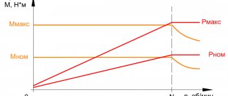
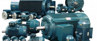
For automated calculation of a typical scheme, you can use a specialized online calculator. The following example demonstrates the calculation of the correct connection of an electric motor:
- winding connection - triangle;
- power consumption – 1,200 W;
- mains voltage – 220 V;
- cos ϕ – 0.9;
- Efficiency – 85%;
- capacity of the working (starting) capacitor – 52 (130) µF.
Capacitor or battery
The use of such products instead of batteries is limited by the insignificant capacity of serial electrolytic models. The situation changed with the advent of ionistors, which are characterized by increased capacity (up to tens of thousands of farads). Listed below are features to consider when comparing capacitors and batteries.
Advantages of ionistors:
- long-term preservation of good operating parameters;
- wide temperature range (from -40°C to + 60°C);
- reliability;
- ease of handling;
- reasonable cost.
Flaws:
- rapid self-discharge (15-25% in 24 hours);
- relatively small energy reserve (1-1.5 mA per 1 F).
Correct application of capacitors requires accurate preliminary calculations. As energy storage devices, these elements are used in conjunction with solar panels. In such sets, during continuous operation, the indicated losses can be considered acceptable. If you have to disconnect the power source for a long period of time, using a battery seems preferable.
Energy of a charged capacitor. Online calculator for any capacitors.
Content:
Decimal.
Common fraction a/b. Product of numbers a*b. Pi number (π). Euler number e. E is the letter meaning 10n. Square root Sqrt(x). Root of any degree Root(n, x). Exponentiation of Pow(n, x). Logarithm of the number Log(n, x). Natural logarithm Ln(n). Decimal logarithm Lg(n). Binary logarithm Lb(n). The greatest common divisor of the gcd Gcd(n, m). Least common multiple of the LCM Lcm(n, m). Trigonometric functions. Sine of the angle Sin(x). Cosine of the angle Cos(x). Tangent of the angle Tan(x). Cotangent of the angle Cot(x). Angle secant Sec(x). Cosecant of the angle Csc(x). Inverse trigonometric functions. Arcsine of angle Asin(x). Arc cosine of angle Acos(x). Arc tangent of angle Atan(x). Arc cotangent of angle Acot(x). Arcsecant of angle Asec(x). Arccosecant of angle Acsc(x). Expressions containing multiple nestings of functions and mathematical operations. Decimal
Notation: To write a decimal, use a period or comma Example: 1.12 or 1.12
Common fraction a/b
Recording: To enter common fractions, use the “/” sign Example: 1/2 or 3/4
Product of numbers
Recording: To write the product of two numbers, use the “*” sign Example: 5*4
Pi (π)
Writing: To write the number π, enter “π”, either “pi” or “pi”. Example: Sin(π)
Euler number e
e = 2.7182818284… Write: To write the number e, enter e or E. Example: Cos(e)
E – letter meaning 10n
Entry: The letter E must only appear in a number Example: 16e+6 16e-4 3.96e+3
Square root Sqrt(x)
Notation: Sqrt(x), where x is any non-negative number or expression. Example: Sqrt(3) Sqrt(3/5) Sqrt(3*3)
Root of any degree Root(n, x)
Notation: Root(n, x), where n is the radical expression x is the degree of the root x, n is any numbers or expressions. For a root of even degree, the radical expression cannot be negative. Example: Cube root of the fraction 2/5 Root(2/5, 3) Other examples Root(1.5, 3) Root((3*5), 3/2) Root(1.5, 3/7)
Exponentiation Pow(n, x)
Notation: Pow(n, x), where n is the base x is the exponent of x, n is any numbers or expressions. Example: Five to the power of three Pow(5, 3) Other examples Pow(12.5, 3) Pow((3-5), 3/2) Pow(1.5, Sqrt(2))
Logarithm of a number Log(n, x)
Notation: Log(n, x), where n is the number whose logarithm you want to find x is the base of the logarithm. x > 0, x ≠ 1, n > 0 Example: Log5 34 (logarithm of the number 34 to base 5), write it as Log(34, 5)
Natural logarithm Ln(n)
The base is equal to the Euler number e (e = 2.7182818284...) Notation: Ln(n), where n > 0 Example: Ln(7)
Decimal logarithm Lg(n)
The base is 10 Write: Lg(n), where n > 0 Example: Lg(1.6)
Binary logarithm Lb(n)
Base is 2 Write: Lb(n), where n > 0 Example: Lb(3/6)
Greatest common divisor GCD Gcd(n, m)
Notation: Gcd(n, m), where n, m are non-negative integers Example: GCD(12, 16) should be written as Gcd(12, 16)
Least common multiple of the LCM Lcm(n, m)
Notation: Lcm(n, m), where n, m are non-negative integers Example: LCM(4, 23) should be written as Lcm (4, 23)
Trigonometric functions
All trigonometric functions take either one or two arguments. If the function takes one argument, then the number is taken as radians.
Sine of angle Sin(x)
Recording: Sin(x) Sin(x, measure) Where x is the number measure - can take the values Rad or Deg Example: Sine π/3 radians Sin(π/3) or Sin(π/3, Rad) Sine 60° degrees Sin(60, Deg)
Cosine of angle Cos(x)
Notation: Cos(x) Cos(x, measure) Where x is the number measure – can take the values Rad or Deg Example: Cosine π/3 radians Cos(π/3) or Cos(π/3, Rad) Cosine 60° degrees Cos(60, Deg)
Tangent of angle Tan(x)
Recording: Tan(x) Tan(x, measure) Where x is the number measure - can take the values Rad or Deg Example: Tangent π/3 radians Tan(π/3) or Tan(π/3, Rad) Tangent 60° degrees Tan(60, Deg)
Cotangent of angle Cot(x)
Recording: Cot(x) Cot(x, measure) Where x is the number measure - can take the values Rad or Deg Example: Cotangent π/3 radians Cot(π/3) or Cot(π/3, Rad) Cotangent 60° degrees Cot(60, Deg)
Angle secant Sec(x)
Recording: Sec(x) Sec(x, measure) Where x is the number measure - can take the values Rad or Deg Example: Secant π/3 radians Sec(π/3) or Sec(π/3, Rad) Secant 60° degrees Sec(60, Deg)
Cosecant of angle Csc(x)
Notation: Csc(x) Csc(x, measure) Where x is the number measure - can take the values Rad or Deg Example: Cosecant π/3 radians Csc(π/3) or Csc(π/3, Rad) Cosecant 60° degrees Csc(60, Deg)
Inverse trigonometric functions
All inverse trigonometric functions take either one or two arguments. If the function takes one argument, the function will return the answer in radians.
Arcsine Asin(x)
Notation: Asin(x) Asin(x, measure) Where x is the number measure - can take the values Rad or Deg Example: Arcsine 1/3 (receive the answer in radians) Asin(1/3) or Asin(1/3, Rad ) Arcsine 1/3 (receive answer in degrees) Asin(1/3, Deg)
Arc cosine Acos(x)
Recording: Acos(x) Acos(x, measure) Where x is the number measure - can take the values Rad or Deg Example: Arc cosine 1/3 (answer in radians) Acos(1/3) or Acos(1/3, Rad ) Arc cosine 1/3 (receive answer in degrees) Acos(1/3, Deg)
Arctangent Atan(x)
Recording: Atan(x) Atan(x, measure) Where x is the number measure - can take the values Rad or Deg Example: Arctangent 1/3 (receive the answer in radians) Atan(1/3) or Atan(1/3, Rad ) Arctangent 1/3 (receive answer in degrees) Atan(1/3, Deg)
Arc tangent Acot(x)
Recording: Acot(x) Acot(x, measure) Where x is the number measure - can take the values Rad or Deg Example: Arc cotangent 1/3 (receive the answer in radians) Acot(1/3) or Acot(1/3, Rad ) Arccotangent 1/3 (receive answer in degrees) Acot(1/3, Deg)
Arcsecant Asec(x)
Recording: Asec(x) Asec(x, measure) Where x is the number measure - can take the values Rad or Deg Example: Arcsecant 1/3 (receive the answer in radians) Asec(1/3) or Asec(1/3, Rad ) Arcsecant 1/3 (receive answer in degrees) Asec(1/3, Deg)
Arccosecant Acsc(x)
Notation: Acsc(x) Acsc(x, measure) Where x is the number measure - can take the values Rad or Deg Example: Arccosecant 1/3 (answer in radians) Acsc(1/3) or Acsc(1/3, Rad ) Arccosecant 1/3 (receive answer in degrees) Acsc(1/3, Deg)
Expressions containing multiple nestings of functions and mathematical operations
Any expression can contain multiple nesting of functions; the expression length limit is 100 characters. Enter an expression (maximum length 100 characters). Examples: Root(Pow(3, 6), 2); (5/2-4)*34/5-(Root(3, 2)) (12-123+5)/(12.45*(34/6)) Sin(60, Deg)+Cos(45, Deg) etc.