A good and reliable power transformer is already half of the structure being assembled and developed. Currently, the choice of power transformers offered by the market for radio amateurs is quite wide. But despite this, not all proposed transformers are ideal for the needs of a radio amateur (in terms of current, voltage, number of windings, etc.), and therefore quite often he has to independently manufacture power transformers for his designs and assembled structures. In this article I will try to explain how to choose or calculate the right power transformer for your design. I will not reveal anything new here, and I will try to explain to you as simply as possible and with examples what has long been proven and decided. Simply due to some circumstances, not everyone can know this.
Basically, a radio amateur has to make power transformers with an average power of 50 - 300 W. The efficiency of such transformers reaches 0.88 - 0.92. For more powerful industrial transformers, with powers of more than 1 kW, the efficiency can reach 0.97-0.98, since their windings are wound with thick wire and losses in them due to active resistance are minimal. For less powerful transformers, with a power of up to 40 W, the efficiency decreases and usually does not exceed 0.8 - 0.85.
To correctly calculate a transformer, you need quite complex calculations, radio amateurs use simplified formulas and amateur radio programs for these purposes, which, in principle, also allow this to be done quite accurately, so I will also try not to deviate from this tradition and will try to explain everything using practical examples and ready-made calculations using a minimum of formulas and calculations.
As usual, the power transformer is calculated. Knowing the voltage and current that the secondary (or several secondary) windings (U2 and I2) should provide, we find the power of the secondary circuit: If there are several secondary windings, the power is calculated by adding the powers of the individual windings. The power of the secondary winding P2 according to Ohm’s Law is equal to;
From here you can find the power of the primary winding, where for medium-power transformers we take the transformer efficiency of 0.9 (90%) to our calculations. For transformers of lower power, the efficiency is correspondingly lower (0.8). The power of the primary winding P1 (transformer power) in this case will be equal to;
That is, let me explain, if the calculated power of the secondary winding(s) is, for example, 100 W, then the total power of the transformer will be equal to 111.1 W (100/0.9). This does not yet take into account the no-load current, which is also added to the total power of the transformer.
We have understood how to determine the power of the primary winding, now how to correctly determine the power of the secondary winding? To do this, we have some kind of load that consumes a certain current at a certain voltage. For example, there is a load that consumes a current of 2 Amps at a voltage of 15 Volts. It seems that it could be simpler, according to Ohm’s Law we multiply 2 by 15 and voila - we get 30 W. Yes, this is true, the current supplied by the secondary winding will be equal to the current consumed by the load, but only when the secondary winding is loaded with an active load! For example, the filament winding of lamps. If the secondary winding is loaded with a load through the elements of a rectifier, or a rectifier and a filter, then the situation takes on a completely different turn. The current supplied by the secondary winding will be greater than the current consumed by the load! Why is this so, let's try to figure it out together. We will not consider the operation of the secondary winding on an active load, everything is clear here, let's move on.
Operation of the rectifier for an active load.
Half-wave rectifier.
Let's place a rectifier diode in front of the load. That is, we have a half-wave rectifier.
Let's put together the same circuit. My transformer is toroidal, with a power of 60 W, with a voltage of the secondary winding about 20 volts (rated load current 3.8 A, rated voltage 16.5 Volts), current of the transformer XX is 7 mA. To measure its current, I placed a 1.0 Ohm resistor in the gap of the primary winding, and a 0.1 Ohm resistor in the gap of the secondary winding (series with the load). To measure alternating and pulsating current and voltage in circuits, I used a root-mean-square (RMS) microvoltmeter B3-57, and for measuring in DC circuits, a Mastech MY64 digital multimeter.
For measurement safety, this entire structure was connected via an isolation transformer. Variable wire resistances of various values with a power of 25 W were used as load resistors. The effective load current was set to 0.5 amperes (figure above). The measurement limit is 100 mV, the shunt in the secondary circuit is 0.1 Ohm. The resistance of the variable resistor was 19 Ohms, the effective voltage at the load was 9.5 volts. That is, the power consumed by the load turned out to be 4.75 W. Let's measure the current consumed by the primary winding.
The primary winding current turned out to be 97 mA, minus 7 mA XX, for a total of 90 mA. The voltage on the primary winding is 215 volts. The power consumed by the primary winding turned out to be 19.35 W, that is, 4 (four) times more than the power of the consumed load. Why is that? For those who are interested in all the details of the processes taking place in a transformer, I recommend reading the primary sources given at the end of the article; for those who are too lazy to read, I will try to explain it in a simple way.
When installing a diode in series with the load, we get a half-wave rectifier. The load is supplied with a voltage (current) pulse only during the positive half-cycle, and nothing during the negative half-cycle (pause). As a result, the average voltage on the load decreases by more than two times (more precisely by 2.2) compared to the voltage on the secondary winding. The average current through the diode corresponds to the load current, and the effective current of the diode and the secondary winding itself is 1.57 times greater than the load current. Let's calculate the power of the secondary winding; Load current is 0.5 A, multiply by 1.57 = 0.785 (secondary winding current). We multiply the resulting current by the voltage of the secondary winding (19 Volts) 0.785x19 = 14.9 W - this is the output power of the secondary winding, plus transient processes during operation of the diode (valve) are also added here, plus reactive currents that simply heat the winding, in As a result, the power of the transformer is at least 3.5 times greater than the power consumed by the load. Even when this circuit is operating, a constant component appears in the secondary winding (due to the fact that the current in the winding flows only in one direction during one half-cycle), which magnetizes the transformer core and the greater the load current, the greater the current. Because of this, the properties of the core deteriorate and the XX current increases, as a result of which the power consumption of the transformer increases (we got 4 times more power).
For example, already with a load current of 1.0 Ampere, the load voltage was 9.0 Volts, the load resistance was 9.0 Ohms, the load power was 9.0 W. The primary winding current turned out to be 230 mA (minus 7 mA) for a total of 223 and the voltage on the primary winding was 210 volts. The total power consumption of the transformer is 46.83 W, that is, 5.2 times more than the power consumed by the load. The idle current increased greatly with increasing load current (which increased the magnetization of the core).
Full-wave rectifier.
Well, we've sorted out the half-wave rectifier, let's move on. Let's see how the full-wave circuit behaves. What is a full-wave rectifier circuit? These are two half-wave rectifiers that operate on a common load. Each rectifier has its own winding, but unlike the other, it is antiphase, as a result of which both half-cycles are rectified (entered into the load), due to which the efficiency of such a rectifier, compared to a half-wave rectifier, increases twice.
Let's see how he behaves. Let's assemble a full-wave rectifier circuit. This circuit requires a transformer tapped from the midpoint of the secondary winding. The transformer is different, the secondary winding has a voltage of 193-193 Volts, its current is 36 mA (as I found it). Using wire resistors I set the load current to 150 mA.
The load resistor turned out to have a resistance of 1.17 kOhm, the measured voltage across it was 175 Volts. The power consumed by the load turned out to be 26.17 W. Let's look at the current of the primary winding.
The primary winding current is 210 mA, minus the XX current (36) for a total of 174 mA. The power consumed by the transformer was 38.28 W. This is 1.46 times more power consumed by the load. As you can see, the performance here is much better than that of a half-wave rectifier. Go ahead.
Bridge rectifier circuit.
Let's check how the bridge rectifier circuit behaves. To do this, we will assemble the following diagram.
Let’s take the transformer that was there before, with one secondary winding from the first case under consideration for a half-wave rectifier. I set the load current to 0.5 A, the variable wire resistance turned out to be 32 Ohms. Load voltage 16 Volts. The power consumed by the load turned out to be 8 W.
We look at the current consumed by the primary winding.
Primary current 53 mA minus XX current (7 mA) = 45 mA. The power consumed by the primary winding was 9.9 W. This is 1.23 times more than the power consumed by the load. As you can see, the performance here is even better than that of a full-wave rectifier, not to mention a half-wave rectifier.
Operation of a rectifier on a load with capacitive response.
Basically, radio amateurs use in their practical activities rectifiers with smoothing filters starting with a capacitor (capacitor), that is, a load with a capacitive response. There is no point in rewriting textbooks; for those interested, the list of references is at the end of the article. I’ll just briefly outline here the basic circuits of rectifiers used by radio amateurs, their features and approximate electrical characteristics, and how they affect the overall power of the transformer.
Half-wave rectifier.
Let's start as usual with a half-wave rectifier.
In such a rectifier, the filter capacitor is charged to the amplitude value of the voltage of the secondary winding (in the absence of load). That is, if the secondary voltage is 10 Volts, then the capacitor will charge to 10x1.41 = 14.1 Volts (this is without a voltage drop across the diode). Advantages of a rectifier;
Simplicity of the circuit, only one valve (diode, kenotron) is used.
Flaws;
Greater dependence of the output voltage on the load current, lower ripple frequency compared to other circuits, which requires the use of capacitors with twice the capacity, poor use of the transformer (low efficiency), and forced magnetization of the core.
When the valve breaks down, alternating voltage is supplied to the capacitor, which leads to its failure and explosion. Features of the scheme;
Used by radio amateurs to power low-current circuits. The reverse voltage in this circuit applied to the valve is approximately three times greater than the voltage of the secondary winding (more precisely 2.82 times), why this happens - try to determine for yourself. That is, if your secondary has a voltage of 100-110 Volts, then the diode must be set to a reverse voltage of at least 400 Volts; it can break through at 300 Volts. The average current through the valve here corresponds to the load current, and the effective value of the current through the valve is twice the load current.
The secondary winding for a half-wave rectifier is selected to be 1.8 -1.9 times higher in current (preferably 2 times) than the load current consumption. To the total calculated power of the transformer, if there are other windings, add the power of this load of yours multiplied by 2.
Full-wave rectifier.
A full-wave rectifier has much better parameters than a half-wave rectifier. The output voltage of this rectifier (capacitor voltage) is 1.41 times higher than the secondary winding voltage (half). This is when there is no load. Advantages of a rectifier;
Small number of valves used (2).
The average value of the current through the valve is almost two times less than the load current. The ripple level of this circuit is 2 times less compared to a half-wave rectification circuit. The capacitance of the capacitor, with the same ripple coefficient as the half-wave circuit, can be 2 times less. There is no forced magnetization of the core, but this depends on the design of the transformer and the method of winding the windings, which will be discussed below. Flaws;
The transformer has a complex design, the secondary winding consists of two halves, hence the inefficient use of copper.
The reverse voltage per valve here is also 2.82 times greater than the voltage (half) of the secondary winding. Poor use of the transformer, since the total calculated power of the entire secondary winding turns out to be 2.2 times the power consumed by the load. Features of the scheme;
Since in one period, in this circuit, both halves of the secondary winding work in turn, and accordingly, the valves (diodes) also work in turn, the average value of the current through one valve (per period) here is almost two times less than the load current . That is, for example, if you put diodes with a permissible constant current of 5 Amps in this circuit, then you can remove 7-8 Amps from this rectifier without much risk of failure of the diodes, naturally providing them with the necessary cooling. The effective current through the valve and the secondary winding here will be 1.1 times greater than the load current. The wire for the secondary winding in this circuit can be chosen 30-40% less in current (cross-section) than the load current, since the halves of the secondary winding also work in turn and the average value of the secondary winding current is less than the load current. But it is better, if the dimensions of the transformer and capabilities allow, to wind the secondary with a wire of the appropriate cross-section with the load current.
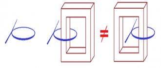
About the forced magnetization of the core. If the transformer core is W-shaped, armored, and all the windings are placed on one frame, then there will be no forced magnetization of the core. If the core of the transformer is rod-based and the design of the transformer includes two frames on which the windings are placed, and the network winding consists of two halves placed on different rods (TS-180, TS250), then the secondary winding in such transformers must be performed as follows; Each half of the secondary winding is divided in half again and wound on different rods, then everything is connected in series, first quarters of one half, then the other. As below in the picture. Otherwise there will be magnetization of the core.
Since kenotrons have high internal resistance, when choosing a kenotron rectifier circuit, the voltage of the secondary winding (half) is selected on average by about 10-15% less than the planned output voltage of the rectifier. It also depends on the load current. The higher the load current, the smaller the difference should be. Also remember that in all rectifiers, both with kenotrons and with diodes, the filter capacitors, when there is no load, are always charged to the amplitude voltage of the secondary winding (UC = U2 x 1.41). Take this into account when choosing the voltage of the filter capacitors.
How can we roughly determine here how much power will be added to the total power of the transformer? Without delving deeply into the theory, since there are a lot of factors that depend on each other, you can do the following;
Knowing the calculated load current, we multiply it by 1.7 (circuit with kenotrons), or by 1.6 (circuit with diodes), then multiply the result by the load voltage. This will be the approximate result of the received power, which will be added to the total power of the transformer. There won't be a big mistake here.
Bridge rectifier.
A bridge rectifier, like a full-wave rectifier, has much better parameters than a half-wave rectifier and slightly better efficiency than a full-wave rectifier. Therefore, this is the most common scheme. Advantages of a rectifier;
The average value of the current through the valve is almost two times less than the load current.
The ripple level of this circuit is 2 times less compared to a half-wave rectification circuit. The capacitance of the capacitor, with the same ripple coefficient as the half-wave circuit, can be 2 times less. There is no forced magnetization of the core. Only one secondary winding is used. Flaws;
Poor use of a transformer, since it is necessary to increase the calculated power of the secondary winding by the value of the amplitude value of the voltage of the secondary winding, i.e.
1.41 times. An increased number of valves used (4) and the need to shunt them with resistors to equalize the reverse voltage on each of them. Although this is no longer so relevant given the modern quality of their performance. The voltage drop is also twice as large compared to other circuits, since the rectified current passes through two valves in series. But this is noticeable only at low output voltage and high load currents. Features of the scheme;
In this circuit, just as in the full-wave circuit, the average value of the current through one valve (per period) is almost two times less than the load current. That is, you can also use diodes with a lower operating current (30-40%) than the load current. But the effective current of the secondary winding will always be higher than the load current, at least by 1.41. Therefore, the wire for the secondary winding in this circuit must be selected 1.5 times larger in current (cross-section) than the load current. Why, because the rectifier will always charge the filter capacitor to the amplitude value of the voltage of the secondary winding, and the power is calculated from the value of this voltage. And since, according to the law of conservation of energy, it does not disappear anywhere, the secondary winding has no choice but to constantly make up for this difference. That is, for example, our secondary winding has a voltage of 14 Volts. The filter capacitor will have a voltage of about 20 volts. We loaded it with a current of 0.5 Amperes. The power turned out to be 10 W. This means that the secondary should deliver 10 W, and with an output voltage of 14 Volts it will be a current of approximately 0.71 Amperes, that is, 1.41 times more than the load current.
The secondary winding in the bridge rectifier circuit will always supply energy to charge the capacitor up to the amplitude voltage value, and the load will discharge it. That is, it is like a step-up converter, where the low-voltage part is the secondary winding, and the high-voltage part is the filter capacitor. Therefore, the secondary winding current will always be higher than the load current by this voltage difference, that is, at least 1.41 times.
For example, you found a transformer with an output voltage of 24 Volts and a load current of 5 Amps (120 W). We assembled a linear adjustable power supply, connected it to a 12 Volt load and a current consumption of 5 Amps (60 W). It seems like everything should be fine. We drove for half an hour or an hour, there was a smell of burning, we touched the transformer and got burned. How so?
Let's check what we had with the transformer; The load current is 5 Amps, the voltage on the filter capacitor in XX mode will be 24x1.41 = 33.84 Volts. The power consumed by the load will be 33.84x5 = 169.2 W, and this does not depend on the output voltage of your power supply, at least 5 Volts, at least 25. The rest of the power will simply be lost on the regulating transistor. And it turns out that within an hour our trance delivered power to the load of 170 W!!!, although its power was 120.
Conclusion; For a bridge rectifier circuit, the cross-section of the secondary winding wire must be selected at 50% or 1.5 times greater than the planned load current to ensure normal operating conditions of the transformer, or choose a transformer for your design with a secondary winding current higher than planned by the same amount, so as the load current on the transformers is indicated for a resistive load.
Well, accordingly, the power of the secondary winding is calculated as follows: We multiply the load current by the voltage of the secondary winding and multiply the resulting result by 1.5.
AudioKiller's site
The power supply is the most important part of the amplifier. An amplifier works like this: it transfers energy from the power source to the load. If the power supply is not working well, then no amplifier will help you get what you need from the load. To power amplifiers, a bipolar source is widely used, which produces two identical voltages of different polarities relative to ground. To obtain such a power source, you need a transformer with two secondary windings (or one with a terminal from the middle), a corresponding rectifier and a filter of two capacitors.
You can have more capacitors, but two is the minimum. But what about the rectifier? There are actually two possible rectifier designs. One contains two diode bridges, the second - only one (Fig. 1).
Fig.1. Two variants of bipolar rectifier circuits.
There is an opinion, actively supported on audiophile Internet forums, that the left circuit, which contains two bridges, is much better than the circuit with one bridge. But why? The explanations given are very meager, unclear and contradictory. After much questioning, I finally managed to find out the reason. It is as follows (in my retelling): the Spirit of Audio lives in every amplifier, and the diode bridge is a kind of sacrifice, a tribute to this spirit. If there are two bridges, then the tribute to the Spirit of Audio is twice as large. The Spirit will thank you for this by improving the sound. If you thought I was mocking you, yes, but just a little. It’s just that for some reason all the explanations boiled down to this. The attempts at scientific explanation were so pathetic that I could never understand them. If someone can explain from the point of view of science and technology why two bridges are better than one, I will be happy to listen. And I will discuss. In the meantime, I will present to you my vision of this problem. Scientific and technical.
The sound of a device is determined by how that device and all of its constituent components operate. And not only in general, but also in detail. Therefore, if we achieve the best performance from the power source both in general and in small details, then we will do everything to ensure a good sound from the amplifier. And all sound improvements (of course, if it doesn’t seem to you that it sounds better, self-hypnosis is a very insidious thing) come from improving the technical characteristics (that is, work) of the equipment components, and not according to an incomprehensible rule like “this is necessary for good sound” .
So what is the difference between the schemes.
1. Two bridges are larger in size, have double heating (I will prove this below), and are twice as expensive. That is, according to this criterion, two bridges are worse than one.
2. For one bridge, you can use any transformer - both with separate windings and with output from a midpoint. And for two bridges only a transformer with two separate windings. That is, not every transformer is suitable for a rectifier with two bridges. The scheme is less universal, let's write a minus for it.
3. In a circuit with two bridges, each winding of the transformer operates on its own rectifier, which in turn operates on its own power supply arm of the amplifier. Those. one arm of the amplifier is powered from one secondary winding of the transformer, the other from the other. In a single bridge circuit, each arm of the amplifier is fed from each of the secondary windings of the transformer in turn. We will see this clearly. Then we will decide what is better. For now, let this be a mystery.
4. Let's consider how currents flow through rectifiers. In Fig. Figure 2 shows the flow of current through a rectifier with two bridges. In Fig. 3 – current flow through a rectifier with one bridge.
Rice. 2 Current flow through a rectifier with two bridges.
Rice. 3. Current flow through a rectifier with one bridge.
Note that in a two-bridge rectifier, the current of each leg always flows in series through the two diodes. And in a rectifier with one bridge - only through one diode. Consequently, the voltage drop across the rectifier diodes in a two-bridge circuit is twice as high. And a little less voltage reaches the amplifier. You can say: “Just think, what a small thing!” Not that it’s a trifle - it is from this voltage that the voltage at the output of the amplifier is obtained. Since the supply voltage has decreased, the maximum possible voltage at the load will also decrease. This means that the maximum output power will also decrease. How much? Let's look at how much.
For greater clarity, consider an example. Let's say the transformer produces 30 volts in each of the windings under load. The forward voltage drop across the diode is 1.2 volts. Why so big? Because the voltage drop across the np junction at high current is added to the voltage drop across the internal resistance of the diode. This forward voltage drops on almost any silicon diode at a forward current of 3 amperes or more. This corresponds to an amplifier current of 1 ampere - after all, the current through the amplifier is continuous, and the current through the diode flows in short pulses of large amplitude. Let's say the minimum residual voltage at the output transistors is 4 volts. Load resistance 4 ohms.
We count for amplitude voltage values.
Two bridges.
Maximum load voltage:
Maximum output power:
The factor 2 in the denominator of the last formula takes into account that we are using amplitude voltage values, and not effective ones.
One bridge.
Maximum load voltage:
Maximum output power:
The difference is as much as 7 W, or 10%. And just these seven watts of maximum output power may not be enough for you, and clipping will begin!
By purchasing and putting two bridges in the circuit, you will have to pay more to get 7 W lower output power!
5. It is said that a circuit with two bridges is less susceptible to DC bias of the transformer when the amplifier reproduces a signal with a frequency of 25 Hz. This is wrong. Magnetization occurs when a current with a frequency of 25 Hz is consumed from the secondary winding. Those. the two secondary windings in this case work as one, regardless of the rectifier circuit. The main thing is that they transmit their current to the primary winding, in which everything happens.
So we have four reasons why a rectifier with one bridge is better than one with two. And not a single one showing the advantages of a rectifier with two bridges.
Oh yes! I haven’t proven that two bridges heat up twice as much as one. Look at Figures 2 and 3. The amplifier current passes through two diodes in each of the bridges. And the currents of both arms of the amplifier are on average the same (over a fairly long time, which determines heating - seconds and tens of seconds). In one case, the current passes through one bridge, and in the other, exactly the same current passes through two bridges. Heating is caused by current. Two bridges mean twice the heating, each bridge heats up equally, whether in a circuit with one bridge or in a circuit with two. Therefore, two bridges produce twice as much heat as one.
Now let's return to the riddle in point 3. Is there a difference if each arm of the amplifier is from its own transformer winding, or if each of the secondary windings works on both arms of the amplifier in turn. Here's the thing... The secondary windings of a transformer are not always the same. Even if their numbers of turns are equal. In an armored and toroidal transformer, the windings are wound one on top of the other. The one on top has a larger average coil diameter than the one on the bottom. Hence the different resistances and different voltage losses when current flows. And different stray fields (which means their no-load voltages may differ). Here on my desk is a high-quality 2x28 volt 75 VA toroidal transformer. The resistance of its secondary windings is 0.7 Ohm and 0.75 Ohm. In fact, these are small things, and the real voltage difference across the windings is very small. But it happens. This transformer of mine has 28.6 volts and 28.65 volts under load. If the voltages of the secondary windings do not differ, then everything is fine. But what if there is a difference? And it is quite possible. Then the supply voltages supplied to each arm of the amplifier will look like in Figure 4.
Rice. 4. Voltages at the rectifier output at different voltage values of the secondary windings of the transformer.
If there are two rectifier bridges, then each arm of the rectifier (and amplifier) is powered by its own winding. With your tension. And in one shoulder the tension is greater, in the other less. The maximum output power will be determined by the lowest voltage! Let's say the voltage of the positive side in our example is 0.2 volts less than the negative side. So, the voltage created by one of the windings is not 30 volts, but 29.8 volts. We count.
Maximum load voltage:
Maximum output power:
Lost a whole watt. A trifle, of course. But it’s a pity! What if the voltage difference is greater? You never know what kind of transformer you managed to purchase! And in a homemade transformer, everything can be even worse.
For one bridge the picture is completely different. There, each winding works alternately on each load arm. The maximum voltage in each arm is equal to the highest of the winding voltages. It's great to get the most of everything! A clear advantage over a scheme with two bridges. The price to pay for this will be the presence of ripples with a frequency of 50 Hz in the rectified voltage, while a two-bridge rectifier produces ripples only with a frequency of 100 Hz. Pulsations with a frequency of 50 Hz are filtered less well. Is there a downside to this? No! We have two reasons not to be afraid of these lower frequency pulsations:
1. The amplitude of these ripples is very small and is equal to the voltage difference of the secondary windings. In our example it is 0.2 volts.
2. The filters of modern amplifiers use large capacitors, which effectively smooth out everything. 50 Hz pulsations are smoothed 2 times worse than “standard” ones with a frequency of 100 Hz. But the amplitude of hundred-hertz ripples is tens of volts (it is equal to the supply voltage). And yet it is effectively suppressed. And here are fractions of a volt.
So, in all respects, a single-bridge rectifier is superior to a two-bridge circuit. And if you don’t believe in the Spirit of Audio, then you need to use it. Let me tabulate the results of our example for greater clarity.
| Scheme | With one bridge | With two bridges | With two bridges |
| Option: | for all cases | equal voltages of secondary windings | different voltages of secondary windings |
| Maximum output power, W | 76,8 | 69,6 | 68,4 |
And how much additional money and space do you need to spend to get 68 W instead of an output power of 76 W?
But that is not all. Now let's remember that there are Schottky diodes in the world. I have already written about the fact that their increased performance when rectifying a sinusoid with a frequency of 50 Hz does not manifest itself in any way. But they have another very remarkable property: a much lower forward voltage drop. I measured it for diodes of several types, it turned out to be almost the same and equal to 0.7 volts. That is, compared to diodes with an np junction, we gain as much as half a volt. Is this too much? I will repeat all the calculations for our example, using Schottky diodes as diodes, and again tabulate everything.
| Type of rectifier diodes | "Regular" diodes | "Regular" diodes | "Regular" diodes | Schottky diodes | Schottky diodes | Schottky diodes |
| Scheme | With one bridge | With two bridges | With two bridges | With one bridge | With two bridges | With two bridges |
| Option: | for all cases | equal voltages of secondary windings | different voltages of secondary windings | for all cases | equal voltages of secondary windings | different voltages of secondary windings |
| Maximum output power, W | 76,8 | 69,6 | 68,4 | 80 | 75,6 | 74,4 |
So, by replacing the "regular" diodes with Schottky diodes, we gained a few extra watts to the maximum output power. Who knows, maybe just these watts were not enough for us to be completely happy? And is it necessary to kill this happiness with your own hands, putting two bridges where one is sufficient? Two bridges, even with Schottky diodes, are inferior to one bridge with “regular” diodes.
And note that the difference between the largest maximum output power and the smallest is 11.6 watts. Imagine! We can lose as much as 11 watts simply by designing the rectifier differently. So much for the difference in the circuits and rectifiers.
In fact , to be honest, a double-bridge circuit still has an advantage over a single-bridge circuit. In a two-bridge circuit, the maximum reverse voltage on the diode is half as much. The maximum reverse voltage on the diode for a two-bridge circuit must exceed the voltage (rms value) on one secondary winding by at least 1.5 times. It is much better if it is 2 times or more. And for a single-bridge circuit, the maximum reverse voltage on the diode must exceed the voltage on one secondary winding (if there are two separate windings, or on half, if it is one winding with a tap from the middle) by at least 3 times, and preferably 4 or more times. Therefore, if you use a diode bridge with a maximum reverse voltage of 200 volts, then a single-bridge circuit will provide a maximum of ± 60 volts, and a double-bridge circuit will provide ± 120 volts of power. If the bridge can withstand 1000 volts of reverse voltage (and such bridges are readily available and cheap), then a two-bridge circuit will produce a maximum supply voltage of ± 600 volts, and a single-bridge circuit will only produce ± 300 volts. Is it enough for you? Therefore, I don’t consider this property an advantage: install bridges designed for a voltage of 1000 volts and don’t worry about anything. The situation is worse with Schottky diodes - they are much lower voltage. I have not seen Schottky diodes with a maximum reverse voltage exceeding 150 volts. Then in a double-bridge circuit we will get a supply voltage of a maximum of ±100 volts, and in a single-bridge circuit - ±50 volts. Typically, ±50 volts is sufficient for most amplifiers. But if you really need more, then you have to choose what to sacrifice. And again, look at the table: one bridge using conventional diodes is slightly more efficient than two bridges using Schottky diodes. So the choice is yours.
11.09.2016
Total Page Visits: 5582 — Today Page Visits: 8