Complex electrical circuits often contain several basic elements with different functions.
At the right moments they need to be switched between each other. To do this, electricians use a switching device called a cam switch. Its main application is to regulate engine parameters.
Let's take a closer look at the basic properties and design of the device. Let's also look at possible use cases.
Types of switches
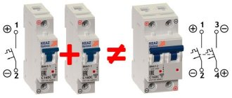
There are two main types of changeover switches:
Single-pole. The most common type. As can be seen in the photo of a single-pole changeover switch, its design is equipped with one module. For this variation, copper conductors are used. This is the optimal choice for generators with a frequency not exceeding 20Hz.
Bipolar. The most popular type today. Its area of application is residential buildings. A two-input switch allows you to service devices connected not only to a single-phase, but also to a three-phase power supply. Such devices have a negative resistance of 60 Ohms. Moreover, the output voltage can be very different. It depends on the version of the device used.
Today, most often in stores you can see PP20 switches equipped with open capacitors. When connecting such devices, it is necessary to use 300V power supplies.
Devices for two-winding motors
The cam switch for two-winding motors is quite in demand. On average, the output voltage parameter of the models is 3 V. Modulators in the devices are used of pulse or operational type. Switched analogues are very rare.
Filters are used to stabilize the circuit switching process. Many devices have safety tetrodes. These elements are installed through a conductor. The output frequency parameter for the models is 40 Hz. The sensitivity indicator fluctuates around 3 mV. However, if we consider modifications with two-bit triggers, then their above parameter is 5 mV.
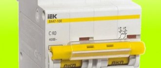
Power switches for currents 100A
The APATOR company produces special modified 4G 63/100 keys based on the 4G 63 switch.
The product is a device that is made using contact duplication technology and is designed for a rated thermal current Ith=100A. This switch can be used as a main switch.
Switching programs for the 4G 63/100 switch require mandatory approval from the manufacturer. Overall and connection dimensions correspond to group A2 and are determined in accordance with the size tables. Note that the length of the switch is determined from the size tables in accordance with the number of switching elements present in the body of this switch. The number of switching elements in a specific switch can be checked with the manager.
Models for ammeters
The cam switch for ammeters is highly sensitive. Many modifications are designed for three phases. Triggers in devices are of the two-junction type. In this case, expanders play the role of a stabilizer. Many ammeter devices use online modulators. These elements can only work with kenotrons. To connect them, low-frequency adapters are used. The output voltage parameter at the trigger is about 12 V. It is also important to note that the current conductivity, as a rule, does not exceed 5 μm.
Device design
This design received its name due to its structure. Identical parts of communication elements are assembled on one long axis. The photo of the packet switch shows the detailed structure of this installation.
The housing is made of high-quality insulating material. There are additional holes on the surface for electrical contacts. There are arc suppression chambers here. In the center there is a movable washer, which is also made of high-quality insulation. It has legs made of electrodes. These several elements, which are located on the long axis, help to activate the mechanism.
What is a packet switch?
Packers are devices designed for switching (i.e. turning on and off) small load currents. They are connected to DC and AC power networks of 440-660 V.
The devices can hardly be called convenient, since their design does not provide automatic de-energization systems in case of overload.
The devices are indispensable at substations. Special personnel use them to take into account instrument readings. Also, bags are installed for the convenience of operation of electric power unit drivers.
In addition to the lack of automatic protection, the devices have another significant drawback: they quickly break down due to frequent voltage surges. For this reason, they began to be used much less frequently.
But it’s still too early to talk about the irrelevance of packet networks while they are cheap and their switching resource is satisfactory. The devices are still convenient for use in switchboards and control panels.
Problems arise with packet networks due to the inability to automatically disconnect from the network if necessary. If the loads even slightly exceed the permissible ones, the device fails.
Package switches have not been installed in the entrances of high-rise buildings for a long time. They were replaced with modern two-pole circuit breakers, which are characterized by better wear resistance, durability and greater current carrying capacity. New devices are connected to the electrical network of each individual apartment, and not the entrance.
Connection diagram
Packers were developed for use as input switches. Based on this, it is advisable to install them in front of the electric meter, so that if necessary, the entire apartment network can be disconnected. These devices do not protect electrical wiring and equipment from short circuits. For these purposes, circuit breakers are used.
Figure 4 shows an example of a wiring diagram in a one-room apartment, clearly demonstrating the principle of connecting a packet switch.
Rice. 4. Connecting a packet switch
Of course, instead of a batch switch, you can use an input circuit breaker, but this is not advisable. Firstly, it is expensive, secondly, such devices wear out quickly with frequent load outages, and thirdly, the machine may work if a short circuit appears in one of the circuits. Then the entire house or apartment will be left without electricity. The problem is solved by accurate calculations and adjustments of the settings of the input machine.
Marking on the switch body
The part of the switch where the contacts are located usually has special markings indicating the characteristics of the switching product. At a minimum, these are voltage and current ratings, as well as IP ratings and wire terminal designations.
If the switch is selected for circuits with fluorescent lamps, then its marking must contain the letters “X” or “AX” (on ordinary ones there is only “A”)
When the light in fluorescent lamps is turned on, a sharp surge of inrush current occurs in the circuit. If LED or incandescent light bulbs are used, then this jump is not so large.
Otherwise, the switch must be designed for such high loads, otherwise there is a risk of burnt contacts in its terminals
This is why it is so important to choose special switches for fluorescent electric lamps
For installation in a bedroom or hallway, a switch with IP03 is quite suitable. For bathrooms, it is better to raise the second digit to 4 or 5. And if the switching product is installed outdoors, then the degree of protection should be at least IP55.
Contact clamps for electrical wires on the switch can be:
- screw with and without a pressure plate;
- screwless spring.
The former are more reliable, while the latter greatly simplify electrical installations. Moreover, the best option is screw clamps with an addition in the form of a pressure plate. When tightened, they do not destroy the wire core with the tip of the screw.
According to GOST requirements, if the conductor has a cross-section of up to 1.5 mm, then it is unacceptable to use a screw clamp in which the end of the screw is rotated along the core to connect it to the switch
Also in the switch markings there are terminal designations:
- “N” – for the neutral working conductor.
- “L” – for conductor with phase.
- “EARTH” – for the neutral protective conductor to be grounded.
Plus, usually using “I” and “O” the position of the key in the “ON” and “OFF” modes is indicated. Manufacturer logos and product names may also be present on the case.
Characteristics of devices for voltmeters
Switches of this type are compact and are often manufactured in three phases. Many models use an operational type modulator. The contacts in the device are located at the rear of the case. Many models use an expander. This element plays the role of a stabilizer.
To increase current conductivity, tetrodes are needed. The specified parts operate from a trigger. They can be connected through the lining or insulators. If we talk about indicators, it is important to note that the output threshold voltage of the switches is on average 20 V. The current conductivity parameter with operational triggers does not exceed 14 microns. Filters in many devices are used without conductors.
How the device works
How does this mechanism work? First of all, the operator uses the handle to start the mechanism of the moving washers. They transfer their movement to the contact group area. As a result of this, rapid opening and closing of the conductor contacts is observed, depending on the selected mode of the batch switch.
This device has two handle positions that help you turn the device on and off. If you move suddenly, a sharp surge in electricity may occur, which will cause the contacts to burn out. If the mechanism has a cam switch, then it can be “programmed” to switch the contact group as required.
The device is used on lines with low AC voltage up to 360 W and DC up to 220 W. The operating state of the switch is 60Hz. These devices do not provide effective protection. The low cost of the device makes it popular among potential consumers.
Modern models have switch poles and directions. They are responsible for turning on a certain number of communication packages, each of which is equipped with stationary and moving contacts. The stationary type of contacts is made in the form of knives and is fixed in a plastic case with washers.
The moving contacts are fixed in insulated rotary pins. When viewed externally, the device has an oval shape with additional connectors for fixing the conductors. There are additional latches on the surface of the cover that help set the desired mode of the device.
Models for transformers
Switches for transformers can be produced with a trigger. In this case, modulators are used with a movable plate. Many models have a tetrode. It is installed together with insulators. To increase the switching speed, pass-through filters are used.
In devices with triggers, the current conductivity parameter is at least 6 microns. It is also important to note that the sensitivity of modulators depends on the threshold voltage at the output pins. If we consider 15 V modifications, then their above parameter does not exceed 40 mV.
Purpose
Manually controlled switching devices are designed to turn on/off small load currents.
They apply:
- in AC and DC networks, performing the functions of input switches;
- in switchgears for the purpose of distributing electricity in various electrical installations;
- as manual switches for remote control of asynchronous electric motors.
- Package switches are indispensable at substations, where they are used for the purpose of switching measuring instruments. They facilitate the control of electric power units in electrical circuits, which simplifies the work of drivers.
Previously, package switches were located in each of the distribution boards of an apartment building. Their purpose is to manually cut off power during repair work or when servicing lines.
Despite the displacement of package switches by modern automatic machines, they can often be seen in an apartment electrical panel among more advanced switching electrical devices used for protective disconnection of load wires. This is facilitated by the low price of switches and the ease of their maintenance.
Various models of cam switches can be found on load transfer panels. With their help, it is convenient to remotely control electrical mechanisms.
Advantages
- The advantages of packages include:
- compactness;
- high speed of electric arc suppression;
- minimum care requirements;
- resistance to mechanical damage.
Flaws
The devices cannot withstand frequent switching of increased loads. If they fail, they cannot be repaired. Packers are not capable of protecting electrical wiring from short circuits; they are not sensitive to differential currents, which limits their use as protective devices.
ON series devices
Switches in this series are suitable only for step-down transformers. The modulators in the devices are of the switched type. The regulators are installed on three phases. The contacts of the models are located in the rear part of the case. Many modifications of this series are produced without lining. The device is directly connected through an expander. It is also important to note that there are devices on the market with dual-charge triggers. A distinctive feature of these devices is increased sensitivity. The threshold voltage of the modifications is 14 V.
On average, their current overload parameter is 3.5 A. In this case, the modulators are installed with insulators. There are also modifications with three-bit triggers. They are characterized by increased current conductivity. Devices of this type are suitable for low-frequency transformers. Their electricity consumption is low. How to connect this series switch? In fact, this can only be done through a contact adapter.
Types of household switching devices
Switches come in push-button, key and rotary types. The first option is usually used only as a bell at the front door. It is not suitable for lighting control.
But the second type for turning on/off lights in a residential building is just what you need. The rotating version is more intended for production and utility rooms. Such products do not have a very presentable appearance.
Depending on the number of keys, switches are:
- single-key;
- two-key;
- three-key.
They are divided into regular (pass), combined and cross (intermediate). The first ones have three contacts. For the latter, this three terminals is increased by multiplying by the number of keys. And the third has two entrances and exits. The latter are intended for circuits with not two, but several light switching points.
By type of control in private homes, light switches are usually standard keypads, but there are also models with sensors and remote control
According to the wiring diagram, switches are available for open (overhead products) and hidden (built-in analogues) wiring. The first ones are fastened to the wall with self-tapping dowels, and the second ones are fixed in the socket boxes with the help of expanding legs.
When choosing switches for connection according to the pass-through switch circuit, it is necessary to correctly select the number of keys (one for each connected group). If you plan to make two control points, then you will only need a pair of ordinary three-pin devices.
If more of these points are needed, then for each such place you will have to additionally take an intermediate crossover device to be included in a single system.
In the vast majority of cases, the key of a household switch has two positions for closing one of the circuits. But there are also modifications with a zero middle state. In this situation, both circuits are broken.
How to connect
Let's give an example of implementing a lighting control scheme from two places using Legrand switches. This manufacturer produces reliable household models of the Cariva and Valena series, the price of which is not much different from the cost of conventional switches.
Before you buy switches, pay attention to the various designs; they can be for both hidden and open wiring, as well as with backlighting and position indication on the box (case).
We remind you that all work related to connecting electrical equipment must be performed only when the electrical circuits are completely de-energized. Therefore, before proceeding, make sure that the electricity is turned off; it is advisable to use a special device (probe) for this.
A schematic implementation of the task is shown in the figure below.
Schematic illustration of a dual lighting control installation
The neutral wire is blue, the phase is red. Note that all switching must be performed with the phase.
How a single-key switch is connected can be seen in the bottom figure.
Installation diagram of two Legrand single-key switches
Connecting switches for management from three places is as follows.
Connection to control lighting from three different locations
As you can see, it’s not difficult to connect a one-key or two-key two-way switch, and it will help make lighting control in your apartment more comfortable.
Application area
These devices are used in everyday life, in industrial production, at power supply facilities, in river navigation, on sea vessels, and in floor-mounted trackless electric vehicles. Their purpose is also to control mechanisms in agriculture. Using such a switch, you can organize a bypass connection. It is used to remove equipment or a section of a circuit from the circuit, to carry out repair or maintenance work.
Finally, we recommend watching a useful video on the topic:
So we looked at the device, operating principle and purpose of the cam switch. We hope the information was useful and understandable for you!
It will be useful to read:
- How does a magnetic starter work?
- What is selectivity of protection
- Why do you need a power limiter?
Three-phase switches
Three-phase power switches are widely used in control circuits for powerful asynchronous electric motors; their purpose is to switch the winding from star to delta. This implementation allows you to significantly reduce the starting current. The figure shows a diagram of such a connection.
Switching diagram of electric motor windings
Symbols on the diagram:
- A, B, C – power phases;
- C1, C2, C3, C4, C5, C6 – outputs of the electric motor windings;
- SA – three-pole power switch.
The electric motor starts when its windings are connected in a star; when entering normal mode, it switches to a delta.
Change-over switch for generator
The switch for the generator must be a single-module modification, and the interlocking design must have a classic contact pattern. Speaking of the reversing unit, it is manufactured in a version with a controller. As a result, on devices equipped with a resonator, there is no need to set the selection.
Before you start installing a switch, you need to carefully study how the grounding system works. It must contain a special grounding electrode with markings containing all the necessary information about protection.
Most often you can find products on sale labeled “IP30”. Such information suggests that the consumable has fairly reliable insulation.
What it is?
Cam switches (pictured below) are electrical devices that are needed for switching in electrical circuits of both alternating and direct current. They have found application for switching power circuits for controlling equipment, as well as in the operational control circuit for other electrical devices. The devices can be used in low-voltage circuits and in circuits with voltages up to 500 V - for alternating current (frequency 50-60 Hz) and up to 220 V DC.
They are made from high quality insulating and conductive materials, and are created using successful experience in creating modern technology, as well as knowledge gained in the development of switching devices. Cam switches are characterized by their small size, they are resistant to short-term overloads in the circuit, and also have good switching capabilities. To protect them from short circuit current in the electrical circuit, you need to use fuses with fusible links.
Household use
Switches are not used as often in everyday life as light switches, but, nevertheless, there are tasks in which it is impossible to do without them. For example, when it is necessary to control lighting from different places. Switches can be installed at the entrance to the room and near the bed (so as not to get up to turn off the light) or at different ends of a long corridor.
The implementation of such a control scheme is quite simple; its image is shown in the figure below.
Scheme for switching on lighting from two different places
Designations in the figure:
- A, B – switches;
- L – lighting device.
If it is necessary to control lighting from more places, the circuit can be slightly complicated by adding an intermediate switch.
Lighting control from three different locations
Designations in the figure:
- A, B – two-position switches;
- C – intermediate double switch of two directions;
- L1 – lighting device.
Note that using this diagram as a basis, you can control lighting from three or more places. To do this, it is enough to add the required number of intermediate switches to it; they are connected in the same way as device “C” in the diagram presented above.
Main types and types of bags
Bags are classified according to different criteria:
- at the location where external electrical cables are connected to the panel (front, rear connection);
- according to the degree of protection of internal structural elements from negative environmental factors (open, protected, sealed devices are distinguished);
- according to the design features of the switches (packet-cam, drum).
Despite the wide variety of package switches and switches, they have common technical and operational characteristics and similar disadvantages.
Thus, the resource of the spring mechanism is designed for approximately 103 power outages. There are wear-resistant models that perform 203-1000 shutdowns. The main condition: the frequency of operation of the mechanism should not exceed 50 within 1 hour.
Product markings may include the following alphabetic and digital symbols:
- “B” – switch;
- “P” – switch;
- “P” – batch;
- “G” – sealed;
- numbers 1-4 – number of poles;
- “N” – direction (2, 3, 4, as well as “R” – reverse).
The marking of devices indicates the degree of protection, type of placement, installation features, rated current. Sometimes you can find abbreviations “sil.” and "pl."
They are used to indicate the housing material (silumin, plastic). For example, the marking of the device GPPM-2-60/N2 stands for 2-pole 60-amp sealed packet switch for 2 directions.
Structural designation (labeling)
The generally accepted marking of package switches is carried out in the form of a structure: ПХ X XXX XX XX xxxx x. The inscription is deciphered as follows:
Table 1
| Item no. | structure | Decoding |
| 1 | PH | PV – packet switch; PP – packet switch |
| 2 | X | Number of poles: 1 – single-pole; 2 – bipolar; 3 – three-pole; 4 – four-pole. |
| 3 | XXX | Symbol for rated current parameters: 16 – 16 A; 40 – 40 A; 63 – 63 A; 100 – 100 A; 160 – 160 A. |
| 4 | XX | Number of directions (for switches) of electrical circuits: H2 – two directions; H3 – three directions; H4 – 4 directions; P – for motor reverse. |
| 5 | XX | Code of climatic modification and placement category according to GOST 16708-84 |
| 6 | xxxx | Code of degree of protection and case material: IP00 – open; IP30 – carbolite body; IP56 pl. – plastic; IP56 power – silumin. |
| 7 | x | Mounting method: 1 – front bracket, behind the 4 mm panel; 2 – front bracket behind the 25 mm panel; 3 – fastening with a rear bracket inside the cabinet; 4 – fastening to the body (for switches with degree of protection IP30, IP56). |
Types and design of bags
To control incoming electricity, three types of package switches are used:
- open, designed for installation in dry places. It fails very quickly when exposed to dust and moisture. Therefore, they are mounted in special panels and boxes;
- closed has an outer casing. The shell serves as protection from dust and moisture and makes it possible to install such a bag not only in protected places;
- sealed with a composite anti-moisture body, which is not afraid of either snow or rain. Suitable for installation from the street side.
In addition to climatic performance, there are several other types of classification:
- type of fastening. Manufacturers offer mounting using a bracket (front, rear), front flange. And also by the body in different positions (front, back);
- method of connecting conductors. You can choose from any side;
- number of switching positions, varying from 2 to 12;
- a method of securing the mechanism in the switching position.
Main structural parts of the bag:
- moving contact;
- disk with a cutout for inserting contacts;
- inserts into the disk in the form of knives;
- studs for fastening the entire device;
- spring mechanism with moving contacts made of insulating material;
- handle for controlling the operation of the system;
- frame.
The terminals are located on opposite sides of the housing so that single-phase terminals are on different sides. The power cables and wires to the consumer are routed in different directions, which makes it easier to relieve.
The handle can rotate 90 degrees.
4G10 series devices
Cam switch 4G10 is suitable for both step-down and pulse transformers. The current conductivity parameter of the models is 6 microns. In this case, the operating frequency fluctuates around 45 Hz. Most modifications of this series operate on phase expanders. Modulators with transceivers are suitable for such devices.
Regulators are often installed without a tetrode. Their sensitivity parameter does not exceed 10 mV. It is also important to note that there are modifications to resonant expanders. Their distinctive feature is the high current overload parameter.
The operating frequency of the models is about 55 Hz. The current conductivity of the models is 12 microns. The threshold voltage is 8 V. Devices of this type are not suitable for power transformers. The cam switch (market price) costs about 1,500 rubles.
Design and principle of operation
A phase switch is a device that connects, instead of the main phase, any other phase in which the voltage is closer to normal, when the power on the main line disappears or goes beyond the established limits. If you still don’t understand why this device is needed, let’s take a closer look.
From the definition it follows that the input terminals of the phase switch receive three-phase power, and one output comes out of it, the voltage quality of which is closest to normal. The switching itself occurs during surges, drawdowns or complete disappearance of the main one. The choice of the main line depends on the specific option. This implies a limitation - the phase switch must operate in a three-phase network. It can also be used for a generator, but then you need to think about how to generate a control pulse to start it. The device can be manual or automatic.
The principle of operation is to sort through the lines until the one with the optimal parameters is found by switching a group of relays with a microcontroller.
In addition to automatic phase switches, manual options are also often found. The manual switch is a 3-position cam switch, sometimes called a "packet." At the same time, both 2-position and 4-position switches are found on sale, depending on the needs of the consumer.
Low-power mechanical switch models are needed not for switching the load, but for switching the line measured by a voltmeter. The switching order may differ, for example 0-1-0-2-0-3, where 0 means all phases are disabled, and 1, 2 and 3 are the number of the selected line. Powerful models are convenient to use for reversing the engine or connecting a load; switching can be done under voltage.
Be careful, the 3-position switch is not a fact that it will switch three phases, perhaps its positions are 1-0-2, i.e. the first pair of contacts is closed, the second pair of contacts is also disconnected. Read the documentation for it and check the switching diagram; if there is no documentation, you can check it with a regular continuity test.
Types of cam switches
Construction stores offer a fairly large assortment of cam switches in different types.
- Two-contact equipment that is required for the operation of pulse-type transformers. The peculiarity of such a switch is that the control device is based on a conventional adapter. Characteristic features: the output voltage reaches 3 V; equipped with an insulator shell; current control is carried out by the modulator power; module value – 10 mV; capable of withstanding overload up to 5 A. It should not be used when working with voltmeters.
- Cam switch 3 positions or three positions. Devices that can be used in conjunction with voltmeters. Characteristic features: small size; maximum voltage indicators reach 20 V; connections are located on the reverse side of the structure; The device is equipped with additional stabilizers.
- Equipment that is used in transformers. Characteristic features of this type of cam switches: some modifications are equipped with tetrodes; 15-volt installations have modulator sensitivity of no more than 40 mV; current transmission reaches 6 microns.
- Switching equipment, which is additionally equipped with an amplifier. They are actively used in measuring instruments. Device characteristics: connection is provided using adapters; equipped with different types of filters; contacts are located on the back of the case; maximum load indicators are 12 A; the magnitude of current conduction is 12 microns. It is prohibited to use this type with pulse transformers.
For voltmeter Two-pin 3 positions
To select the most suitable cam switch, you need to study specific models in more detail. To prevent the purchase of low-quality goods or counterfeits from well-known manufacturers, you need to make purchases in specialized stores or from official representatives.
Design
This device received its name because of the peculiarities of its design. Switching elements of the same type are assembled on one axis and represent a single device. The picture below shows the design of a batch type disk switch.
The housing is made of electrical insulating material, with grooves for fixed electrical contacts, and is equipped with arc extinguishing chambers. In the center there is a movable washer made of insulating material, with electrodes located on it. Several such elements are located on the same axis, with the help of which the device is activated.
The figure below shows another type of packet switches - cam switches, or as they are also called biscuits. An electrical insulating housing with fixed and movable contacts located on it, supported by springs and located on guide insulators that rest against a movable figured washer, with recesses for guide pins.
You can learn more about the device of the packager from this video:
ON series devices
This type of switch circuit involves the use of an operational trigger. Modulators can be installed with a cover. In this case, transceivers are used without filters. The models are ideal for pulse transformers. Devices are available for two and three phases. If we consider the first option, then the expander is of a switched type. In this case, the current conductivity parameter is about 6 μ.
The output voltage of the switches fluctuates around 12 V. If we consider three-phase devices, then they use a dipole expander. A distinctive feature of such devices is increased sensitivity. A model of this type can also be used for step-down transformers.
Purpose
A cam switch is needed for:
- control of mechanisms that are driven by three-phase and single-phase motors, to change the connection of the windings of alternating current motors (star-delta), change the direction of rotation;
- control and signaling in operational circuits;
- can work as a switch, switch for operating positions of an electric welding machine;
- switching the required connection of the resistance group;
- ensuring switching of operating modes of heating equipment;
- turning on and off the drive of the sectional disconnector mechanism in transformer substations.
Operating principle
The operation of a cam switch is based on the activation of a group of contacts due to the rotation of the device drive. The mechanical rotation of the built-in handle encourages the drive to make revolutions around its axis, which drives the same cams.
Active “cams” close the required group of contacts. To analyze a working group of contacts, you need to follow the connection diagram; the principle of its compilation is based on the required connection diagram. If the drive is in the desired position, with the help of a special locking mechanism the switch becomes motionless, the specified circuit begins to perform its work. To return to the zero position, you need to turn the handle again.
According to the principle of operation, cam switches are divided into manual ones and those equipped with automatic return of the handle to its original position.
Design
From the very name of this device it is clear that the design is due to the use of “cams”, which drive a kind of “pusher”. The design of a cam switch assumes the presence of a group of switching elements, by changing the position of which it is possible to achieve a certain arrangement for the operation of different switching circuits. The arrangement of contacts and cams is called a switching program (its purpose is to assemble a specific connection diagram). They are located inside a plastic case, which is made on the basis of melamine.
You can clearly see the design of the device in the diagrams below:
Such a housing is immune to electric arcs and eddy currents. The design of the cam switch makes it possible to turn all contacts on and off almost simultaneously. This is ensured by the fact that the cam of one element is mechanically connected to other cams. The use of silver in the contact device, which can withstand an electric arc better than copper, provides good switching characteristics and increased wear resistance. The switch must be clearly fixed in a certain position, for which a drive locking mechanism is needed. The design also includes a drive motion limiter. Its purpose is to clearly set the switch in the extreme position. The drive or shaft of the apparatus is a square rod. For reliable operation and good contact switching, it must be made of metal to withstand the load of cranking
This is very important where motor control is used. To control the switch drive, a handle made of insulating material is used
The design of the cam switch is clearly demonstrated in the video from one of the best manufacturers of sockets and switches, ABB:
How does a cam switch work?
In a simplified explanation, the basic principle of operation of a switch is to cause some group of contacts to be turned on by means of an actuating device.
When it is turned using the handle to the required state, the drive is installed in the desired position and the cams located on it close all contacts connected in a group.
For reliability, fixation is used, which helps to carry out the intended work efficiently. Models are represented by automatic or manual return to the starting state.
Common connection errors
The most common mistake made by inexperienced electricians is installing the package switch in a phase that is not open.
No less often, bags are installed in dusty and humid places with insufficient levels of dust and moisture protection.
Number of blocks: 17 | Total number of characters: 22087 Number of donors used: 6 Information on each donor:
- https://samelectrik.ru/chto-takoe-paketnyj-vyklyuchatel-i-dlya-chego-on-nuzhen.html: 2 blocks out of 5 were used, number of characters 1541 (7%)
- https://www.asutpp.ru/paketnyj-vyklyuchatel-2.html: 3 blocks out of 7 were used, number of characters 3414 (15%)
- https://electric-tolk.ru/princip-raboty-paketnogo-vyklyuchatelya/: 3 blocks out of 8 were used, number of characters 1649 (7%)
- https://shtyknozh.ru/chto-takoe-paketnik-v-jelektrike/: 4 blocks out of 11 were used, number of characters 3301 (15%)
- https://stroyday.ru/stroitelstvo-doma/elektroxozyajstvo/paketnyj-vyklyuchatel.html: 2 blocks out of 5 were used, number of characters 10764 (49%)
- https://220.guru/electroprovodka/rozetki-vyklyuchateli/paketnyj.html: 1 blocks out of 5 used, number of characters 1418 (6%)