The installation of electronic circuit components is carried out in different ways. One of the most common options is soldering, which ensures reliable contact and strong attachment of parts to the printed circuit board.
It is not very difficult and is accessible even to novice radio amateurs. Soldering SMD LEDs has different features and rules. They are designed to preserve the elements and protect them from overheating. Failure to comply with the requirements leads to the loss of lamps, so it would be useful to consider the issue in more detail.
Factory soldering
In the factory, other soldering technologies are used that allow several boards to be soldered simultaneously. A special robot installs the necessary elements on the base, on the working side of which solder paste is applied using silk-screen printing. It contains solder and flux; when heated, they change phase and perform their tasks. The flux degreases the contacts and provides wetting, and the solder, under the action of capillary effect, flows into the gaps of the connections and ensures a strong connection of the SMD elements.
The process takes place in a special oven, where the board is kept for a certain time. The contact duration and heating mode are selected in such a way as not to harm SMD LEDs. The procedure occurs quite quickly and ensures soldering of elements in industrial quantities.
Important! It will not be possible to repeat this technology at home, since you need to have a full set of equipment and materials. Therefore, it is important for hobbyists to master the process of manual soldering of SMD LEDs using conventional tools and materials.
How to safely unsolder a transistor, microcircuit, diode
Soldering conditions
When creating a workplace, you should pay special attention to its lighting. You cannot solder a radio component in semi-darkness. If your vision does not allow you to clearly see all the details, then you need to wear corrective glasses.
The electronic board must be clearly fixed in space, and the body must be in a stable position. It is best to work sitting or standing on both legs, holding the soldering iron confidently. After all, any wrong move will cause irreparable harm.
Technology for dismantling radio components
The tip of the soldering iron should be precisely placed on the layer of solder located in the socket of one leg of the transistor and quickly melt it.
Then a needle is inserted into this place from the reverse side and the tin is separated from the stem. If there is a dismantling braid or desoldering pump, then use them.
When the design of a radio component allows the use of a metal clamp to remove heat from the housing, then it must be used.
If the space for installing the soldering iron tip is very limited, then they work without using a heat remover.
In this case, special attention is paid to the length of time the radio component remains at elevated temperatures.
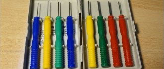
Required materials and tools
To solder SMD LEDs you will need:
- soldering iron with the necessary parameters;
- side cutters, tweezers, scissors;
- mounting needle or thin awl;
- solder and flux. Regular rosin or a special liquid composition, which is an alcohol solution, will do. An aspirin tablet is often used;
- thin brush for applying liquid flux;
- a magnifying glass on an adjustable stand (bracket), which is used by jewelers;
- soldering gun (component of a soldering station).
It will not be possible to do without flux, since molten solder without it does not wet the contacts and does not settle on the metal. Experts do not recommend an alcohol solution of rosin, as it is ineffective and leaves an indelible white residue.
Choosing a soldering iron is an important preparation step. The best option is a soldering station with a temperature control function. However, a regular low-voltage unit with a supply voltage of 12 to 36 V and a power of 20-30 W is also suitable. It is not recommended to work with a standard 220 V device, as their tip gets too hot. As a result, the flux evaporates faster than necessary, not fulfilling its task within the required limits. The maximum heating temperature is 260°.
The type of sting tip is of great importance. A regular cone is not the best option; the optimal choice would be the so-called. microwave. This is a rod cut at approximately 45° with a small recess made in the axial direction. It is filled with liquid solder and allows you to more efficiently apply the material to the SMD LED pads and boards. If necessary, the microwave acts as a suction for excess solder, which avoids drips and drips.
The optimal type of solder is a thin wire with rosin inside. This type allows you to successfully solder LEDs with almost any soldering iron.
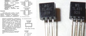
Testing of SMD desoldering nozzle
The moment has come, well known to every radio amateur and electronic engineer, a test for the success of the work. I had one motherboard at hand, socket 775, which I didn’t mind using for experiments (my finger on the south bridge burned after the first second of touch). By the way, I’ll deviate from the topic, in this way, touching all the microcircuits on the motherboard with your finger - this is completely safe, since the maximum voltage on the board produced by the ATX format power supply is only 12 Volts.
If a radiator is installed on top of the microcircuit, then touch the radiator accordingly; if your finger does not tolerate three seconds, there is a very high probability that the microcircuit is broken, there is an internal short circuit or a short circuit with a sufficiently low resistance. This method makes it very easy to diagnose faults without even starting measurements on the board.
Do not try to repeat this method in a device that includes a switching power supply - this is dangerous to life, there is high voltage on the boards of such power supplies!
The board of a switching power supply can be easily distinguished from others by the presence on it of one or two high-voltage electrolytic capacitors, 200 or 400-450 volts, depending on the circuitry used. The same applies to LCD monitors or LCD TVs, as well as to any equipment that does not have an external power supply: almost all of them have a switching power supply, with very rare exceptions (for example, audio equipment).
So let's get back to our testing. The tip was installed in the soldering iron and tightened with a screw. Moreover, one minor trouble awaited here, which, however, was quickly resolved. Arriving at a radio store and asking for a tip for an EPSN soldering iron with a power of 65 watts, I was offered a tip that looked somewhat thinner than mine, but the seller assured that this was a standard tip, saying that everyone was buying it. Having tried to secure it by tightening it with a screw installed on the body of the soldering iron, I discovered that the tip was somewhat slack.
I still have a steel tape rolled into a roll from Soviet times, quite thin. Without thinking twice, I cut off a piece with ordinary scissors, wrap it around the tip, insert it - everything fits perfectly. I tighten the screw and turn on the soldering iron. After waiting for the soldering iron to warm up for 5 minutes, since this is a soldering iron with a nichrome spiral heater, and not a ceramic one, as most modern imported soldering irons are, I finally found a free-standing mosfet field-effect transistor in the SMD version where nearby parts would not interfere - I began to warm it up and try to remove it with tweezers as it warms up, grasping it on both sides free from contacts.
While dismantling the first transistor, I made a common mistake of many newbies: I did not apply flux to the contacts and it took much longer to desolder than the next three. I use homemade alcohol-rosin flux out of habit; I still haven’t gotten used to modern RMA-223. In particular, I spent 40-50 seconds on the first transistor (well, I think that’s it, overheating is guaranteed, it has probably already failed).
The remaining three pieces each took a maximum of 20-30 seconds of warming up, and I removed them not with tweezers, but by slightly rocking the transistor to the right and left, rotating the soldering iron handle and, accordingly, the soldering iron itself and its tip around its axis. As soon as the transistor was able to move slightly from its place, he immediately picked it up with tweezers.
And finally, the moment of truth: we will find out whether our efforts were in vain. Having dismantled four transistors, in order to compile minimal statistics on the possibility of overheating during dismantling, I began to check them using a transistor tester and wires with alligator clips at the ends, connected using a block to the ZIF connector of the device.
I started with the one that had no traces of flux on its contacts, the very first one, which, as we remember, had the maximum probability of failure, since it took longer to solder it than the others. He identified correctly, checked the next three: all were also identified correctly during the tests.
In our city there are points for accepting electronics boards for scrap, for precious metals, and I have long taken the practice of dismantling BIOS chips in the SO-8 package, soldering electrolytic capacitors in a thin case with a nominal value of 1000 uF at 16 V, which are in short supply, on donor boards. And now there is also the possibility of partially removing the mosfets, and in an easy and quick way.
Yes, this could, of course, be done using a soldering gun, but I (and many novice radio amateurs) were interested in precisely this old-fashioned method of dismantling, which I will use in the future for its speed and ease of use.
Total : the costs amounted to 50 rubles only for the cost of the sting. Which, considering the cost of new mosfets in radio stores is about 70-100 rubles apiece, is recovered from the very first dismantled part. Successful repairs to everyone, especially for the site Electrical Diagrams - AKV.
How to solder SMD components
Installation of LED elements is technologically significantly different from connecting a lamp. Soldering SMD LEDs requires some experience and skill. If there are none, it is recommended to first practice on some unnecessary pieces of wire. This will help you master the art of soldering and keep your LEDs in working order. Before starting work, you should inspect the surface of the board. If it is coated with varnish or a layer of silicone, the current-carrying paths to which the LEDs will be soldered should be freed from them.
The specificity of installing SMD LEDs is the absence of conventional long leads. The elements are installed on the board and soldered to the tracks, for which there are small areas on the sides of the LED device housings. The work requires accuracy and attention. It is important to remember the danger of heating, reducing the time the soldering iron touches SMD parts as much as possible. If there is no appropriate tool, a copper wire about 1 mm thick is wound around the tip of a regular soldering iron. One end of this winding serves as a sting, the heating temperature of which is significantly lower than that of the main element. Let's look at the procedure in more detail:
Work order
The soldering process consists of the following operations:
- removing a burnt-out LED (if necessary);
- cleaning conductive paths, applying flux to the soldering area;
- installing a new LED element in place;
- soldering of contacts;
- cleaning the soldering area from flux residues.
It is impossible to make the sting not tremble
Not a single person is able to make a tool (any tool, not just a soldering iron)
) did not tremble in my hands.
Once upon a time I read about masters who paint miniature paintings or murals. The technology they use in their work was described there. Its essence is that it is necessary to coordinate the movements of the hand with the beats of the heart. The inevitable
actually occurs from heartbeats .
There is no need to fight trembling - it is useless. You need to learn to adapt to it.
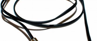
CONNECTING WIRES BY SOLDERING
| You can solder wires to each other in various ways, for example, by placing pre-tinned wires on top of each other and heating them with a soldering iron until the solder melts. |
| This is the result. |
| You can pre-twist the stripped wires. |
| Solder the twist as for tinning. By the way, all examples use solid rosin. If liquid flux is used, it is simply applied with a brush to the desired location. |
| You will get a connection like this. |
| If you are soldering any radio elements without using printed wiring, then here are several ways to solder their terminals. |
| On the left, the conductor is pre-twisted onto the LED terminal, on the right, it is soldered “overlapping”. The first method is more reliable, the second is faster, and in addition, if it is necessary to configure the circuit or replace elements multiple times, it is more convenient. |
| It's just the end result. |
© 2012-2019 All rights reserved.
All materials presented on this site are for informational purposes only and cannot be used as guidelines or regulatory documents.
Hello . Please tell me who and how removes field-effect transistors from the motherboard? That’s why I can’t seem to get the hang of it. Thank you in advance.
- 39861 views
Change the title of the topic, otherwise I can talk about removing field-effect transistors in SOT-23. If we talk about parts in SOT-223, TO-252, TO-263, etc. cases, then you can remove them with different equipment. For example, a 65 W soldering iron. Or a hairdryer. This is a matter of personal preference and having a tool at hand.
The question is certainly interesting.
There is no way to desolder the mosfet with just one soldering iron. For desoldering I use two soldering irons. One at 65 W - I heat the drain of the transistor, the second at 36 W with a wide tip, with which I heat two terminals at once - the gate and the source. To make soldering easier, I first pour a little alcohol rosin around the mosfet. When the leads of the transistor have warmed up until the solder melts, I slightly but sharply lift the mosfet body with two soldering irons at once, it flies off not far to the side (this is fraught with small drops of solder splashed on the board). I solder it with one 65-watt connector (pre-clean the contact pads from solder). And I don’t like to mount/dismantle mosfets with a hairdryer, because I try in every possible way to protect the motherboard from unnecessary local heating. Although, if there was a thermal air vent, I would adapt. it's more convenient than a hairdryer.
There were a couple of cases when the mosfet was in an inconvenient place (for example, under the AGP latch) and had to be desoldered/soldered with a hot air gun; there was no other way to get it. It happened once - I even broke out the latch to get to it with soldering irons.
Partisan of the Underground Moon aka (R)soft
1) SMD soldering station (hair dryer). 2) A pair of soldering irons (undesirable, the transistor overheats greatly). 3) Heating from below (gas burner and other open flame heaters are not recommended). 4) An extreme case regarding DPAK, D2PAK. First heat the leads with a soldering iron and carefully bend them a little (otherwise the case will crack). Next, heat the substrate itself with a soldering iron and remove it.
wiki.rom.by – answers to most questions are specifically collected here!
When others have finished, Intel(R) Pentium(R) processors keep running and running and running.
(R)soft I disagree with you. For 2 years now I have been soldering transistors and microcircuits with one 40W soldering iron (in some exotic case, such as POS-63 - 65W). The question arises with the case - if D-pak - I heat and raise the source and gate, then I warm up and raise the drain, solder the source and gate completely (here you can’t do without a “gear picker”, but you also need to not overdo it - you need to do everything smoothly, because We lift it a little stronger and more sharply - the leg flies away from the transistor); if D2-pak (large), I heat it up and raise the drain, unsoldering the remaining 2 pins. Personally, it seems to me that to get the best soldering result, the main thing is to unsolder the transistor or microcircuit so that the contact pads do not come off - it turns out ugly. Well, of course, sharpening the soldering iron matters. It is soldered with the same 40W soldering iron. It goes without saying that everything is desoldered (well, soldered) using, in the worst case, rosin soldering fat, in the best case, spiroto-rosin flux, soldering paste, and BGA fluxes. It also matters what type of soldering the component will have after mounting the component on the printed circuit board - ideally, soldering should not be noticeable even under a microscope, but seriously - there should be no snot, unsoldered contact pads and other “problems”. As for me, you can’t save on flux and solder; it’s better to spend more remover later on cleaning the printed circuit board from flux, than to later bring the components separately and the board separately.
Read also: What is the temperature of a hair dryer?
A young Intel-ligent MMX processor without harmful gadgets will stick for a long time in a Plug&Play motherboard with three water-output ports for a moderate sound card!
Bird's beak technique
When a bird builds a nest, inserting another branch, it makes short and multiple movements
beak. Even if it is necessary to correct a twig that has already been inserted into the nest, the bird performs each action by making several small and precise movements. In truth, these movements are not always accurate, but in total they still give the desired result.
The main mistake of many beginners is that when soldering they try to make a long
and continuous movement. It's useless. The secret is that you need to make short movements (ideally, they are coordinated with the heartbeats, but you don’t need to specially concentrate on this - over time it should work out by itself).
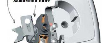
Dismantling by suction
This method of soldering microcircuits and other small parts is based on the principle of liquid suction by creating a vacuum in the contact area.
Vacuum, in turn, can be created using the following tools:
- a special device that operates on the principle of a bicycle pump (it is called a destin pump);
- suction in the form of an enema, which can be combined with a soldering iron and used simultaneously with heating the contact pad.
Suction structures can have a variety of designs (in the form of a piston with a rod, for example), but their essence does not change. They have been and remain the most effective means of removing liquid solder.
Using a razor blade
The main problem with soldering microcircuits is that they have several legs, which is why when one of them heats up, the others have time to cool down. This inconvenience can be overcome by using a heat-conducting device that contacts several legs at once.
In this case, the thermal power of the tip is distributed evenly between them and ensures that the solder melts in several contact areas at once. A simple razor blade can be used as such a device; to heat it up, you will need a soldering iron of suitable power or a hot air gun.
When heating the steel blade, it is recommended to slightly rock the chip on the soldered side, after which you can forcefully pull it out of the board. In the same way, the second row of legs is freed from solder.
Use of medical needles
In the absence of a special suction device, a novice master can use a medical needle to remove the microcircuit. It must be thin enough to fit into the hole being vacated. At the same time, the needle must have a thickness that allows it to be put on the soldered leg.
Before starting operations, you need to file the tip so that the oblique cut turns out straight, and then flare it a little.
Soldering the part with the resulting device is not difficult at all. To do this, you first need to put the needle all the way onto the pin of the microcircuit, and then use a soldering iron to heat it together with the contact.
While the solder is in the liquid phase, slightly turning the needle, you should push it into the mounting hole (it is advisable to continue rotating until the melt sets).
Upon completion of this procedure, the end of the needle along with the leg will be isolated from the board. Do the same with the remaining legs, after which the microcircuit is unsoldered and removed without any difficulty.
HOW TO PREPARE A SOLDERING IRON CORRECTLY
Before soldering, you should properly prepare your soldering iron. Its tip should be evenly covered with solder. Let's look at the photo:
| This is what a “dirty” sting looks like. It is very difficult to solder correctly with such soldering irons. |
| From a cold soldering iron, use a file to remove all the dirt down to pure copper (the material of the soldering iron tip is copper). |
| It should look like this. |
| We heat the soldering iron, sequentially touching the rosin and solder (several times) to achieve uniform coverage of the working part of the soldering iron with solder. |
| The result, having achieved which you can solder. |
Features of dismantling
There are many known technical techniques that allow you to solder a microcircuit with a soldering iron, each of which has its own advantages and disadvantages.
You can remove electronic parts from boards without damaging the contacts in the following ways:
- by heating the soldering areas with just a soldering iron (with the addition of flux);
- through a special suction that removes molten solder from the contact pads;
- using a metal braid from a coaxial cable applied to the soldered leg;
- using heat-conducting metal plates (blades) or copper attachments that have slots for the contact patches of microcircuits.
The first three methods are suitable if you have a soldering iron whose power exceeds 25 watts.
The option of using special attachments involves replacing the working tip and is only suitable in combination with “powerful” soldering stations (more than 40 watts), capable of heating it together with the contacts soldered into the board.
In addition, this method of desoldering a part is only suitable for microcircuits with a suitable arrangement of legs for the configuration of the nozzle. The approach that has become more widespread is when a regular razor blade is used as a heater.