Features of using a three-position switch
Three-Position Change-Over Switch
A three-pole changeover switch is suitable for connecting backup power to a home line. It is used only after the load has been disconnected. The generator will need to be activated and set to working position. Then you need to connect your home network to it. When carrying out repair work, the switch will be used as a disconnector.
Device installation
Changeover electrical equipment is installed in the switchboard. Models with a plastic case are suitable for indoor installation, and metal ones for external installation. Inside the boxes there is a special DIN rail for switches. Installation of devices is carried out as follows:
- Models that switch off under load are installed vertically.
- The type of tires and wires is selected. Their cross section must correspond to the current rating of the switches.
- Buses and wires are connected to fixed contacts.
- The elements are tightly clamped with terminals to ensure reliable contacts and eliminate the possibility of overheating.
- The threads of the nuts are coated with Vaseline.
- Contact nuts tighten smoothly. After the first turn of the wrench, the nut is loosened and then carefully tightened.
- Castor oil is applied to the surface of the contact knives, which will prevent them from jamming in the racks.
- Metal non-current-carrying elements are grounded on the outer part of the box.
Switching order
Before connecting, you must stop the input machine
Three-position or package devices are produced without a disconnector. They connect like this:
- Stopping the introductory machine.
- Installing the device handle on the generator line.
- Switching off the load breaker.
- Connecting the switch cable to the generator socket.
- Start the generator, wait for warm-up (2 minutes).
- Supplying power to the switch.
- Turning on the load breakers.
Machines are installed on each of the inputs.
Connecting the generator to a changeover switch
To organize the coupling, you will need two modular contacts or an electrical switch for 7 contacts. A pair of them should be normally closed, and a pair should be normally open. The connection is made like this:
- It is required to enter the extreme contact of the switch to enter the line and cable of the station.
- The middle contact is brought to the consumer.
- The switch is placed in its original position - connected to the main network.
- During the switching process, power is supplied from the generator.
- The switch is installed in the control panel.
- To warm up the system and supply power after activating the generator, a time relay is installed.
- The backup contactor is energized through the main input communicator via a normally closed contact.
Switching processes are implemented by the user. It sets the switch to neutral mode in case of voltage drop. When it resumes, the first contact is activated, opening the power circuit of the second input.
Two-way modification
When choosing such changeover switches for a generator, you should keep in mind that they can only be used for single-phase circuits. Its design includes 2 pass-through capacitors. For sale you can find not only two-module, but also three-module models. They can work in combination with power supplies having an operating voltage of 300 V. The connection diagram for such a switch may involve the use of a meter. The installation of such a device itself is carried out using jumpers made of copper. Such switches can only work in combination with expansion type switches.
An important point is that electrical panels of any design are suitable for such devices. The changeover switch used for the generator is designed for a threshold voltage, which is 350 V. As for the load parameter, it can have different values. The determining criterion here is the manufacturer of the product. On average, this indicator reaches 30 A.
Types of switches
There are two main types of changeover switches:
Single pole. The most common type. As can be seen in the photo of a single-pole changeover switch, its design is equipped with one module. For this variation, copper conductors are used. This is the optimal choice for generators with a frequency not exceeding 20Hz.
Bipolar. The most popular type today. Its area of application is residential buildings. A two-input switch allows you to service devices connected not only to a single-phase, but also to a three-phase power supply. Such devices have a negative resistance of 60 Ohms. Moreover, the output voltage can be very different. It depends on the version of the device used.
Today, most often in stores you can see PP20 switches equipped with open capacitors. When connecting such devices, it is necessary to use 300V power supplies.
Connection diagrams
Please note that the procedure for connecting the device may differ depending on the type of electrical network.
Connecting devices to a single-phase network
Connecting such a switch to a single-phase circuit is possible only if the selected device is made in a two-pole version. It is also necessary to keep in mind that this device can only function with a power supply whose operating voltage is 300 V.
- For such a modification, the negative resistance indicator will reach 50 Ohms. An important point is that sometimes these switches are supplemented with counters. But such a device as switches can rarely be found when using changeover switches.
- When choosing jumpers to ensure contact between two-pole modifications, only those made of copper should be used.
- To install such devices in residential buildings, you should make sure that there are electrical panels of the KK202 series and other modifications. Due to the discrepancy in performance characteristics, reversing units are not recommended for single-phase circuits.
Connecting the device to a two-phase network
If we talk about the voltage limit with which they are able to cope, then this is the level of 300 V. In such a combination, these switches will be subject to a load that will be about 20 A. Most often, the choice is made on such models of switches, which represent the PP30 series.
According to their design, they are equipped with only two modules. With this design, they will be able to provide an output voltage corresponding to a value of 350 V. The blockers used in them can have different designs
For servicing residential buildings, it is important to ensure that there is an electrical panel. This is a requirement
But the design of control units usually contains thyristors. For the network, the limit of negative resistance is 40 ohms
The contact systems that are implemented in such switches are applicable only to closed-type models. In this case, control of electricity fluctuations is ensured by feed-through capacitors. A device such as a reversing unit performs the task of maintaining the required current frequency. If the choice was made on two different models, then they must be used in combination with the controller. This, in turn, makes it possible to minimize the negative effect of nonlinear distortions that appear in the circuit.
But the design of control units usually contains thyristors. For the network, the limit of negative resistance is 40 ohms. The contact systems that are implemented in such switches are applicable only to closed-type models. In this case, control of electricity fluctuations is ensured by feed-through capacitors. A device such as a reversing unit performs the task of maintaining the required current frequency. If the choice was made on two different models, then they must be used in combination with the controller. This, in turn, makes it possible to minimize the negative effect of nonlinear distortions that appear in the circuit.
Connection diagram to a three-phase network
In the case of installing a switch in a three-phase circuit, it is necessary to use power supplies with an operating voltage of 400 V. It is worth noting that for such purposes it is allowed to use transformers made exclusively in the pulse version.
- The procedure for connecting the device itself is performed using an inverting input. The output current is supplied through a special device, the role of which is performed by pass-through capacitors. For such cases, it is advisable to use switches of a two-module design.
- At the same time, single-module modifications can also be found on sale. Their feature is the minimum threshold voltage limit, corresponding to a level of 350 V. As for the negative resistance indicator, its value in the circuit can correspond to a value of 55 Ohms. To solve this problem, care should be taken to ensure that the design of the switch contains a device such as a blocker.
- Residential buildings must be equipped with special electrical panels, representing the KK22 series. Control units used for such situations can include in their design not only thyristors, but also dinistors.
Installation, transportation and storage of circuit breakers
The enterprises produce open-type switches of three types of manual drive RPS, RPTs, RPB.
All of them can be equipped with PPN-39 or PN-2 fuses, but fuses are not provided as standard. The mounting mount for such switches is a platform on which an open switch with a manual drive in the form of a handle is mounted. Installation of switches RPS, RPTs, RPB is carried out in a vertical position with a maximum permissible deviation in any direction - 5 degrees. In rare cases, a horizontal position when installing the device is allowed.
RPS, RPTs, RPB switches are installed in such a way as to ensure easy access and safety during maintenance. The installation location is selected taking into account the possible occurrence of sparks or electrical arcs to avoid injury to personnel, fire and damage to the surrounding area. Installation must be carried out by a specially trained worker.
Open type switches are positioned in such a way as to avoid spontaneous closure of the electrical circuit under the influence of gravity. The switch handle should not be under electrical voltage, both in working and non-working condition.
Installation of switches RPS, RPTs, RPB is allowed in open areas, provided that they are inaccessible to unqualified employees.
When choosing a location for installing RPB, RPTs, RPS switches, it is necessary to take into account the specific operating conditions for this type of device:
- the ambient temperature can vary from +450C to -400C;
- average daily temperature within 350 degrees;
- relative humidity is allowed up to 50% at a temperature of 400C;
- when the temperature drops to 200C, it is possible to increase the relative humidity readings to 90%;
- installation of switches in mountainous areas requires a height of no more than 2000 meters;
- the zone of mechanical influence of the external environment belongs to group “3”, in accordance with GOST 50030.1
Warehouse conditions for storing switches must comply with the technical conditions provided for by the State Standard.
Transportation and warehousing of RPS, RPTs, RPB circuit breakers provides for temperature conditions from +550C to -450C. It is allowed to keep switches at temperatures up to 700C for a short period of time, up to 24 hours.
Source
How many TVs can be connected to one antenna?
The most common option for everyone is “one screen – one antenna”. However, today you will not surprise anyone with the fact that in one apartment there are two, three or more television receivers. Of course, you can install your own antenna for each of them, but it is much more profitable to connect everything to one common one that transmits a high-quality signal.
Technically, double connection is not complicated: there are special dividers (doubles, tees, etc.), with the help of which one signal arriving through the antenna cable can be divided into several.
If the signal strength is sufficient and high-quality amplifiers are used, the number of TVs connected to one antenna is not limited.
When splitting a signal, keep the following in mind:
Possible loss of power. Under the influence of electromagnetic waves, with the help of which the signal is transmitted, a current arises in the television antenna, flowing through the coaxial cable to the receiving device. However, this current is weak. Any additional resistance leads to losses and ultimately to attenuation. Therefore, when connecting a second TV, you must take into account that the entire system will work either in an area with a powerful TV signal, or you must provide in advance for connecting an amplifier.
Dividers (aka splitters) come in different designs
It is important to remember here: a satellite splitter for receiving terrestrial digital television is suitable, but on the contrary, it is not. In addition, there are divisors with and without coordination. Most of the available models sold in stores use conventional capacitive or transformer isolation, which means that it is necessary to provide space for powering the amplifier even before the divider
Most of the available models sold in stores use conventional capacitive or transformer isolation, which means that it is necessary to provide a place to power the amplifier even before the divider.
You need to connect two TVs to the same antenna, but to different set-top boxes. Connecting to a single receiver is technically simpler, but it combines the signal so that the same picture will be synchronously broadcast on both screens.
Connecting each TV to its own individual antenna means:
Cool! Waste of money!
Double pole switch
This is perhaps the main advantage of devices of this type.
This is the main property of such devices, allowing them to perform quite specific tasks. The reversing unit maintains the required current frequency. When choosing changeover switches for a generator, you must take into account that they are used in a single-phase network. At possible low temperatures beyond the permissible limits, a heating system for the cabinet should be provided in advance.
This is the most suitable option for use in two-phase circuits. The entire electrical network is divided into two parts. Its distinctive feature is a special system of blockers.
In contrast to the automatic switching on of the reserve - ATS, with the help of a reversible changeover switch, the reserve is manually switched on. In addition, units manufactured in an expansion version are common. Before installing products in residential premises, you need to make sure that KK series panels, etc., are installed in them.
Installation recommendations
Modular devices usually have 2 inputs and 2 outputs.
If the generator cannot cope with the power supply to the entire area of the room, you will need to install a more complex switch circuit. Such switches or switches are called multi-section or multi-pole. Therefore, it is advisable to avoid installing them in residential buildings with high energy consumption.
Two-phase network How to connect a switch with your own hands if the network is two-phase? Another distinctive feature of single-pole switches is the low output voltage. Reversing switch switch Hager SF263 for connecting a generator - review
Connection diagrams
Changeover switches used in conjunction with generators can be connected in different ways, depending on the type of specific electrical network.
Single-phase network. Only a two-pole switch can be connected to this network. Such devices operate only in conjunction with a power supply with an operating voltage of 300 volts. The negative resistance is 50 ohms. In some cases, electricity meters are added to the scheme. To ensure normal contact, copper jumpers should be selected. Two-pole switches must be installed in the electrical panel KK202 and other similar modifications.
Two-phase network. This diagram for connecting a generator to the home network is used together with transition-type devices with a 200 V power supply, which is the connecting element. These switches in a two-phase network are used in conjunction with expansion type switches, which makes it possible to use them regardless of the number of modules. The maximum voltage for such devices is 300 volts, and the current load is about 20 amperes. Most often, preference is given to switches of the PP30 series. With two modules, they can reach an output voltage of 350 volts. The control unit circuit contains thyristors. The contact systems used are used only in closed-type models. To control power surges, pass-through capacitors are used. The required current frequency is maintained using a reversible unit.
Three-phase network. The installation of the changeover switch in this case is carried out together with power supplies whose operating voltage is 400 volts. If a transformer is used, its design must be of the pulse type. An inverting input is used to connect the device. The input current is supplied through a special device consisting of pass-through capacitors. In such circuits, switches with two modules are used. However, in some cases, the operation of single-module structures is allowed. They are distinguished by a minimum threshold voltage limit of 350 volts. The negative resistance value is within 55 Ohms.
These devices are recommended to be used in conjunction with a blocker. Residential buildings must have special electrical panels installed. Thus, changeover switches used in conjunction with generators are the best option for such cases. They help control the operating parameters of the network, prevent dangerous situations, and provide protection for devices connected to the network.
Basic mistakes
There are a number of mistakes that inexperienced electricians make.
You cannot connect a mini-power station to a home outlet when the machines in the input panel are turned off. During rare power outages, it becomes a tradition to “throw” the gas generator cable to the nearest connector through a plug. Most people argue: why install a backup input if the power goes out 2-3 times a year. Russian people live by the principle: a man does not cross himself until thunder strikes. Electricians do not recommend even thinking about connecting a generator through an outlet for the following reasons:
- There is no separate machine in the line.
- The socket group is not capable of accepting the main load.
- The human factor comes into play: the owners forget to turn off the input circuit breaker, which leads to overloads and tripping of the protection.
- There is a possibility of an “oncoming collision”: electricity begins to flow from the public network while the generator is running. The unit fails.
- Do not neglect the comfortable and reliable operating system of the unit. It is better to study the diagrams for connecting the generator to the home network and choose the best option. This will save equipment and the electrical network.
The generator must have a power several times less than the wiring capacity. For example, the value for an outlet is 3.5 kW. Otherwise, overheating, short circuit and fire will occur. When the machine is turned on, the power will be restored, and the backup source will break down.
However, in some cases, connecting the generator through an outlet is possible. If the mini-station matches the power, then it can be connected to the distribution panel to the switch contacts, but from the generator side. The best option would be to connect an extension cord to it first, and only then the necessary devices. This will prevent the backup source from connecting to your home network.
At the dacha and in a country house, in case of constant outages of the main source, the reserve is connected through a changeover switch, an automatic start system or a reversing switch.
Advantages and disadvantages of switches
It remains to consider the advantages and disadvantages of these devices. The advantages include:
- Visibility. The device usually has an open or semi-closed design, which means that its serviceability can be verified visually. Well, since you can clearly see the conductive knives and tires, it will not be difficult to determine in what position the breaker is located.
- Simple design. Almost all such switches, including changeover switches, have an extremely simple design. They are very durable, easy to maintain, and their repair usually does not require high qualifications and is inexpensive.
- High switching power/cost ratio. This is perhaps one of the main advantages of the devices. Some of these devices can switch currents of hundreds of amperes, and are relatively inexpensive.
But switch-type switches also have disadvantages. Here they are:
- Increased danger for the operator. Since most devices have an open design, it is very easy to get energized if handled carelessly. Therefore, only qualified personnel are usually allowed to work with such switches, and the switch itself is often placed in a closed cabinet or housing.
- Irregular switching time. The switching speed of almost any switch depends only on the operator’s reaction. When the knives are slowly moved under load, a high-temperature arc can “stretch” between the opening contacts, which is equally dangerous for both the equipment and the operator himself*.
Arc suppression inserts, which are equipped with some types of switches, help fight the arc only partially. That is why the vast majority of electrical equipment manufacturers recommend switching using switch devices only after removing the load using intermediate circuit breakers.
And again from the switch to the switch
So, you have found out the main drawback of manual switches - you need to switch them skillfully, to “and... once!” That is why it is recommended to switch switches after disconnecting the load, so that there are no current surges. No current - no arc. But what to do when switching needs to be done under load?
Switches, including rocker switches, are used for this purpose. In their design, they have special accelerating devices, which, when moving the handle, first store the energy of the hand, and then, with a click, move the knives of the device to another position. You constantly come across such devices without even paying attention to this feature. Typically these are switches that switch high voltages and currents. For example, press the TV's power button. A soft press, then a click - the device switched at maximum speed, regardless of the speed at which the button was pressed. Switches work the same way.
Of particular interest are the so-called three-position designs, which have an intermediate position of the middle contact when it is not connected to either the right or the left:
In this position, no lamps are illuminated because the switch is in the off position.
Like switches, switches can be multi-pole and are able to switch fairly large currents.
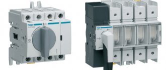
Three-position three-pole changeover switches with a rated current of 25A (left) and 200A.
As can be seen from the photo, they have a closed design. The disadvantages of such devices include the relatively high cost and complexity of the design, but this is compensated by their high reliability and ease of operation.
What is a rocker switch
Reversing changeover switch
The purpose of a changeover switch is to transfer voltage between two lines or connect several networks. Using a switch, you can eliminate current leaks during accidents and quickly switch to the entire line. The device is switched using a lever on the front panel, which is moved to 1-2 positions.
The equipment is installed in the switchboard room or near the input panel.
Device specifics
A toggle-type switch is similar to a two-position switch in its operating principle, but is distinguished by increased power and a smooth blade drive. The second difference is the switching process with a line break and operation in three positions:
- apartment/home network;
- shutdown;
- power supply from the generator.
To understand the principle of operation of a changeover machine, you need to understand the design. The middle contact is a rack in the middle with V-shaped knives. The upper and lower terminals are used as side terminals. The middle contact connects only to the upper ones or only to the lower ones. The knives do not have accelerators or springs, so switching from the main to the backup network is done manually.
Changeover switches
An electric switch ensures disconnection of the network from one energy source and connection to another. The presence of a midpoint explains the name “cross over”. The devices are produced with arc extinguishers that provide switching when the voltage is connected. Models without arc extinguishing mechanisms are switched when the load is turned off. The switch operates only in manual mode - switching is carried out using an isolated control lever.
The design of the device is presented:
- sealed housing;
- movable blade contacts with two working positions and one intermediate;
- arc extinguishing chamber, but there are switches without it;
- terminals for connecting to the network.
Connection to one load line is carried out according to the principle:
- The main power supply is connected to contact No. 1.
- A diesel or electric generator is connected to pin No. 2.
If input into a building with three-phase voltage is required, a three-phase switch with 4 poles is used. The device is connected like this:
- You need to enter the power supply through 4 terminals.
- A generator is connected to 4 terminals.
- The load is connected to 4 terminals.
Zero is connected to one terminal out of four, and phase is connected to three.
Practical recommendations for use
- The device is operated at temperatures from -40 to +50 degrees.
- The reversing switch is installed only in a panel with a mounting panel.
- It is allowed to manually activate circuit breakers with arcing and breaking contacts.
- The burnt contact blade is cleaned with a file or glass paper.
- To prevent the legs from skewing, tighten the mounting bolts tightly.
- All active parts of the device are isolated.
- For manual phase transfer, a transition switch operating in two directions is suitable.
- You need to select a switch according to the power of the current passed.
Changeover switches are suitable for installation in apartment buildings, in production with backup generators. The devices simplify the maintenance of power supplies, monitor power lines and protect the equipment connected to it.
Pros and cons of using switches
An electric switch is the simplest device, which is characterized by advantages and disadvantages. The advantages of operation include:
- Visibility. The device can be visually inspected for damage. The position of the knives is clearly visible.
- Simple design. A small number of components simplifies maintenance and repair of the device.
- High switching current. The switch switches current of 500, 630 or 1000 Amps.
- Low cost. You can purchase a switch for installation in a private house or apartment.
Despite the positive characteristics, the machine has several disadvantages:
- Open type design. All elements are in plain sight; if touched carelessly, there is a risk of electric shock.
- Irregular switching speed. If the knives are moved slowly, a high-temperature arc is formed, which burns out the internal components of the device.
- Possibility of short circuit when a high-temperature arc occurs.
- The occurrence of current surges when switching before the load is turned off.
To protect open parts, the changeover relay is hidden in a special box.
Connecting the generator to the network of a country house
Connecting a backup generator to a private home is a necessity—it’s hard to imagine a modern private home or cottage without electricity. But sometimes there are times when it is turned off during repairs or scheduled work, and it’s good if this happens in the summer, but what if in winter? Heating pumps, a gas boiler, a refrigerator, a well pump are just a small part of what it is very difficult for a person to live without. In such difficult moments, a generator comes to the aid of people.
A gasoline, diesel and gas generator can be connected to the country house network. The only differences are in the network - single-phase and three-phase.
Take a closer look at the number of phases in the generator and the types of their connections:
- connecting a single-phase generator to a single-phase network at home is the most common for a country house, where the voltage is 220V
- connecting a single-phase generator to a three-phase network at home is an economical choice when the voltage in a private house is 380V, but consumers still receive the same 220V
- connecting a three-phase generator to a three-phase network at home is usually required if there are 380V consumers
The most budget-friendly single-phase ones are gasoline generators up to 5-7 kW with forced cooling, which occurs using air from a fan on the motor shaft. They are quite mobile, light in weight and do not make much noise. Such generators have one drawback - the maximum operating time without stopping is usually the time it takes to run out a full tank of fuel, approximately 7-9 hours of operation. If the electric generator automatically turns on after turning off the lights and there is no one at home at this moment, then the operating time of the gasoline generator is limited by the volume of the tank and the thermal mode of the engine, but as a rule, such generators are in great demand due to their availability.
As you can see, when connecting a country house to the network, a 5-7 kW single-phase generator is usually chosen; this is the most economical and correct choice.
More advanced ones are diesel, gasoline or gas-powered generators and usually have a water cooling system, most often with a fan. They are usually three-phase and have an automatic start system when the main line is disconnected; when the voltage returns, they turn off automatically. Such generators have several disadvantages - high price, expensive and frequent maintenance, size, large area of the room and certain conditions in them (heating, etc.) and no mobility. We will not focus much attention on these devices, since they are usually installed by qualified specialists from the service department of the trading organization.
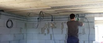
We can do the installation of a generator and wiring in a loft style with modern sockets and loft switches.
Photos of an ABB reversing switch, photos of a changeover, modular switch.
Due to possible discrepancies in performance characteristics, reversing units are not used for single-phase circuits. Video Modern electrical circuits are switched by various devices produced in a wide range.
First of all, it is installed in residential buildings. Such devices are called two-position devices. By means of reversible blocks, the required current frequency is supported. And this is how distribution boards are mainly installed - they have a circuit breaker installed at each input.
A DIN rail can also be used here to accommodate modular protective equipment.
It is also important to remember that for this device it is necessary to use only expansion type switches. The dimensions of the shield are selected according to the number of installed modules. Circuit breakers - polarity and connection diagrams
Choice
The buyer must determine from the very beginning which technical parameters are the most important for him. It is worth taking a closer look at these indicators:
- Weight.
- Dimensions.
- Power.
- Fuel consumption.
- Noise level.
- Duration of work.
Automation and price are parameters that are also being looked at
This is important for those who are interested in how to connect a generator to the home network, the diagram of which is posted on specialized websites
Generator operation
By parameters
Many people first look for an answer to the question of how many phases a generator should have for maximum convenient operation. To do this, you need to understand what electrical appliances will be connected. Three-phase options allow connection to both single- and three-phase devices. Single-phase ones are combined with only one type of consumer. But this does not mean that models with more phases will be better under all circumstances.
At each phase, the maximum load should be no more than 30%. This means that in reality the owners will not be able to use more than a third of the rated power that the outlet initially has. For example, the rated power of a three-phase generator is 6 kW. This means that no more than 2 kW can be removed from a regular 220 V outlet. The load still needs to be distributed over several phases when connecting a single-phase generator to a three-phase network at home.
You might be interested in Autonomous solar power plants for the home
Note! For power, they also check the parameters of the devices that are planned to be connected
It is important to have a reserve of at least 20-30%. Otherwise, you may encounter problems such as overload and work stoppage.
Too much fuel will also be consumed
Otherwise, you may encounter problems such as overload and work stoppage. Too much fuel will also be consumed.
Connection work
Type
Synchronous and asynchronous types of devices are available. The choice involves a careful study of the characteristics of each of the existing models.
Network device
Asynchronous
Their main problem is their inability to handle so-called peak loads. Although these devices can also be used to maintain normal voltage readings. They are suitable for joint use with equipment sensitive to voltage surges:
- Electronic devices.
- Computer Engineering.
- Medical devices supporting gasoline generators.
Residual magnetization of the rotor is the main source of energy for such devices. Therefore, the service life of asynchronous generators is longer than that of their closest analogues. They do not require the use of cooling systems; the unit housing is completely closed. Thanks to this, protection from dust and moisture is fully guaranteed.
Interesting! The asynchronous generator is immune to short circuits. Therefore, this energy source is the optimal solution for welding machines. But such devices can be very sensitive to overloads. Therefore, it is prohibited to connect them to devices with initially high inrush currents.
Devices with autostart
Synchronous
The quality of the current in this case is lower when compared with the previous option. Suitable for providing emergency power in various circumstances:
- Offices.
- Refrigeration units.
- Electrical equipment in dachas and country houses.
- Construction projects.
Such devices also have some positive qualities:
- Resistance to short-term overloads.
- Ability to normally withstand peak loads, including mechanical loads.
But protection from moisture, dust and dirt is worse than that of asynchronous structures. After all, in order to cool, such generators need to pass a certain amount of air through themselves. A synchronous generator will be needed if devices operating with reactive loads are used. Then the power will be less.
Changeover switches
Phasing
It has already been mentioned above. It is worth buying three-phase generators only if there is a consumer with the appropriate characteristics in the house. If all the devices are single-phase, then the generator is selected of this type. This even applies to situations where there is a three-phase network connected to the house.
Network connection
How to make a pass-through switch with your own hands - labor lesson
You've probably already looked at electronic catalogs and noticed that a triple pass-through switch can cost a lot of money. What to do? – The eternal Russian question, reinterpreted by Shakespeare as to be or not to be. We would choose the first: definitely not everyone is able to pay that kind of money for pass-through switches. We present to the attention of our readers the first handmade product in RuNet, where it will actually be shown in pictures how to convert an ordinary switch costing around a hundred (this is a really cheap model) into an expensive thing - a pass-through switch. And without any special skills or special techniques.
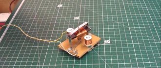
We look at the first picture and see the switch from which the buttons have been removed
More precisely, it was also taken out of the socket (so to speak), but this is not important now. As you can see from the picture, we have a typical connection diagram for 2 keys. Just in case, the screws of the socket box spacers and clamping contacts of suitable wires are shown and labeled with colored lines.
Each and every one of them must be significantly loosened to remove the switch from the wall socket. Do not forget to turn off the power before this, and we also strongly recommend checking with a probe where the phase is located, and somehow draw these places directly along the cambric (plastic insulation of the core). In the future, all this will greatly simplify the process of reinstalling the switch
Just in case, the screws of the spacers of the socket box and the clamping contacts of suitable wires are shown and labeled with colored lines. Each and every one of them must be significantly loosened to remove the switch from the wall socket. Do not forget to turn off the power before this, and we also strongly recommend checking with a probe where the phase is located, and somehow draw these places directly along the cambric (plastic insulation of the core). In the future, all this will greatly simplify the process of reinstalling the switch.
Socket spacer screws
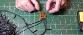
Now look at the next picture, which shows the other side of our future victim. In the good sense of the word, of course. Here we see the switch housing clamps that need to be unbent to remove the electrical part. All this is done with a regular screwdriver within a few minutes. Then you need to remove the spring pushers from the plastic frame. The easiest way to do this is with a thick slotted screwdriver. Thin just won't do. You will quickly understand this. There is no need to rush, because this place is the most difficult in the entire process of converting a conventional switch into a walk-through one. In the picture, the spring pushers have already been removed, and moving contacts are visible in the place where they were.
Movable contacts under spring pushers
We skipped the moment of removing the plastic part from the ceramic one (in the pictures), because in our opinion this does not require explanation. At the ends of the entire removed part of the switch there are two weak teeth. Just pry them off with a slotted screwdriver, and let's start converting a regular switch into a walk-through one. Now on the ceramic base of the switch we see groups of contacts:
Three groups of contacts
- General group contact pads.
- Individual contacts for each light bulb.
- Movable rocker contacts.
Now all we have to do is rotate one rocker arm 180 degrees, and cut off one of the contact pads of the general group (it’s better not to isolate it). The resulting position is shown in the last picture. Now the final stage is how it all works. We take and glue both buttons with a Chinese gun so that they become one. Now that one of our contacts is closed, the second one will hang in the air.
Everything ingenious is simple. Therefore, in addition to the fact that we showed how to make a pass-through switch from a regular one, we will add that, in principle, it is not necessary to remove the spring pushers. You can do without this. And you don’t have to glue the two buttons together if you remove the key from a regular switch of the same width and the same manufacturer. Usually the pinout of the legs is exactly the same. All this will allow you not only to make a pass-through switch with your own hands, but also to produce a truly functional and beautiful product.
So, we believe that we have adequately covered the questions asked. They showed how to properly connect a pass-through switch, how not to do this and - most importantly - told how you can save a lot of money in the whole process. We hope that you will like the recommendations, and now every handy owner will be able to boast of having such an original design in his home. Well, what else would you call a pass-through switch?
Main types of switches
According to electrical engineering terminology, a switch refers to a device that allows electric current to flow through a circuit. Its distinctive feature is a unique system, the action of which is aimed at quickly breaking contact. All functions of the device are carried out by a manual drive, which reliably turns off the voltage during repair and maintenance work.
There are several types of switches, among which the following can be distinguished:
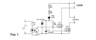
- Reversible (Fig. 1). With the help of these devices, voltage is transferred from one circuit to another. They are mainly used when there is a need to switch the current supply from the emergency section of the circuit to the working one. Special switch rooms are provided for installation of devices. This type of switches has high operational and technical indicators.
- Explosive (Fig. 2). Connects to common output circuits, ideal for private houses, apartments, office buildings. This device is used to connect an object to a common network. They are installed in the electrical panel with the switch lever leading outwards. There is a wide range of models on the market.
- Reversible (Fig. 3). They are used in three-phase electrical networks, ensuring their normal functioning. With the help of these devices, the load is distributed between the lines, and the current is uninterruptedly supplied to consumers. Installation of switches is carried out in a horizontal or vertical position, all switching is done manually. Certain types of devices can be controlled remotely.
The main part of the switch is the rotary contact system. The design of the moving contact is a knife or a spring-loaded fork, and the fixed contact is a knife or two plates, spring-loaded by means of a steel split ring. In addition, the switch is equipped with a handle or manual drive, contact terminals for connecting wires. A 1-way breaking switch with three poles is equipped with three input and three output contacts, and a 2-way changeover switch has six input and six output contacts. For each pole there are 1 or 2 arc chutes, according to the number of directions.
Types and types of changeover switching devices
The main feature of changeover switches is the number of poles. As a result, each device is used with a specific number of connected devices and electrical networks themselves. Each of these switches comes in one-, two-, and three-pole designs, with some models being four-pole designs.
Switches with one and two poles are designed for single-phase networks, and all others are installed in three-phase networks. Single-pole devices that direct the flow of electricity using a single module have become widespread. They are used for reversing switching and are best suited for use with generators with frequencies up to 20 Hz.
In residential buildings with high energy consumption, a reversing switch is not as effective due to the limited load of 200 A. In addition, such devices are characterized by a low output voltage, amounting to only 200 volts for most models.
A more suitable option for apartment buildings is a two-pole device or a two-way changeover switch. This device also works with a single-phase network and has a resistance of about 60 Ohms. This indicator may differ in different models, so each device is selected for specific network parameters.
2-way reversible devices are used to switch the power supply from a generator or public network and back. In all cases, different connection schemes are used, in accordance with the load and network parameters, including cross-shaped connections. Electricity metering devices can be included in this chain.
Three-way or 3-pole circuit breakers are intended mainly for industrial electrical networks
They require additional precautions, so electrical panels must be used for their installation and connection. Three-phase devices have a high sensitivity threshold and are used together with systems that protect against overloads
What does a pass-through switch look like and work?
If we talk about the front side, the only difference is: a barely noticeable arrow on the up and down key.
What does a single-key pass-through switch look like? You see there are double arrows
If we talk about the electrical circuit, everything is also simple: in ordinary switches there are only two contacts, in pass-through switches (also called changeover contacts) there are three contacts, two of which are common. There are always two or more such devices in the circuit, and they are switched using these common wires.
The difference is in the number of contacts
The operating principle is simple. By changing the position of the key, the input is connected to one of the outputs. That is, these devices have only two working positions:
- input connected to output 1;
- input is connected to output 2.
There are no other intermediate provisions. Thanks to this, everything works. Because the contact switches from one position to another, electricians believe it is more correct to call them “switches.” So a pass-through switch is also this device.
In order not to rely on the presence or absence of arrows on the keys, you need to inspect the contact part. Branded products should have a diagram on them that allows you to understand what type of equipment you have in your hands. It is definitely found on products from Lezard, Legrand, and Viko. They are often absent on Chinese copies.
This is what the changeover switch looks like from the rear
If there is no such diagram, look at the terminals (copper contacts in the holes): there should be three of them. But not always on inexpensive copies the terminal that stands alone is the input. They are often confused. To find where the common contact is located, you need to ring the contacts with each other at different key positions. This must be done, otherwise nothing will work, and the device itself may burn out.
You will need a tester or multimeter. If you have a multimeter, set it to sound mode - it beeps when there is contact. If you have a pointer tester, ring for a short circuit. Place the probe on one of the contacts, find which of the two it rings with (the device beeps or the arrow shows a short circuit - it deviates to the right all the way). Without changing the position of the probes, change the position of the key. If the short circuit is missing, one of these two is common. Now all that remains is to check which one. Without switching the key, move one of the probes to another contact. If there is a short circuit, then the contact from which the probe was not moved is the common one (this is the input).
It may become clearer if you watch a video on how to find the input (common contact) for a pass-through switch.
Other switches.
Because In my switchboards I mainly use modules from ABB, but I don’t have many photos of Schneider Electric, Legrand, Hager switches.
I’ll say right away that these manufacturers do not have similar DIN-rail switches like ABB OT63, except perhaps Hager, who have a HAB switch for 20-63A in their product line.
Hager also has modular switches 1-4pole SBN series from 16 to 125A.
In one of the panels I used SBN 2P switches for 63A, which are quite nice, like the entire Hager module.
Schneider Electric also has modular circuit breakers 1P-4P of the iSW series for 20-125A.
I have not yet used Legrand modular switches. I managed either with automatic machines or in 3-phase switchboards with OT63 switches from ABB.
Thank you for your attention.
Features of the device
Switches are manufactured according to different technical characteristics and parameters. There are many types and models that are commonly installed in residential areas. The main feature is that switching between networks occurs with an open circuit, and there are three positions:
- I City (home line).
- 0 Off.
- II Power supply from generator.
With the help of such devices, manual switching occurs between the main network and backup power. After turning off the power to the main network, you can start the generator and move the switch knob to the desired position.
Self-assembly of a changeover switch for a generator
Making a switch with your own hands is done step by step:
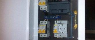
- Selection of machines based on the number of switching circuits. For two-phase, 2 bipolar or 4 single-pole models are installed.
- Installation of automatic machines in the switchboard. One is placed in a standard position, the second is turned over.
- Switching nodes with wires.
- Installing a steel retainer in the pusher (there are gaps for it in the machine). The bar will allow you to switch all the machines at the same time.
- Checking the quality of the system - you should hear a click.
You cannot make a three-position switch yourself - you will only end up with a two-position device.