As you know, an insulated neutral central line is not used in apartment or home electrical wiring. However, for transformers and high-voltage generators, it is an integral part of the entire electrical network.
In this article we will delve into the terminology and scope of the isolated neutral type.
Content:
Precautionary measures
The task and features of grounding transformers.
Now let’s look at why the transformer neutral is grounded, and the physics of how such an electrical network works.
In theoretical physics, the potential of the neutral conductor with respect to the ground should not exceed zero. Repeated grounding at the consumer's receiving device helps to achieve this value with an even higher degree of probability, especially if there is a sufficient distance to the TS.
Electric shock is possible in the following situations:
- Damage to the insulation of live parts, failure of electrical equipment. A step voltage is generated - a potential appears on the floor plane that is unsafe for a walking person;
- Damage to the insulation of electrical equipment. In this case, there may be dangerous voltage on the housing;
- Damage to the protective insulation of the cables. Here the voltage appears on the metal shelves, with the cable lines lying down;
- Violation of the work technology, which led to touching live parts under phase voltage.
It is not recommended to approach a plugged-in wire lying on a wet floor. This situation creates potential that is dangerous for humans. When trying to take a step, the legs are exposed to different potential values. Electric shock guaranteed. To avoid such a development of events, before pouring concrete, a metal frame is laid, connected to the ground loop at at least 2 points. Due to this, if a potential occurs on the floor, the legs of a walking person will be shunted, and electric shock will be avoided.
To prevent the appearance of voltage on non-current-carrying parts of the electrical system, the PUE requires grounding absolutely all metal parts located in the switchgear of transformer substations and consumers, as well as the housings of electrical appliances. In industrial workshops where there is electrical equipment (machines, production lines), a steel strip is laid around the perimeter to connect all metal-containing parts without exception. Thus, the potentials of the ground and metal parts located in the room are equalized.
If a breakdown occurs on a grounded body, the electric current will follow the path of least resistance, i.e. along the grounding conductors to the grounding loop, and not through the highly resistant human body, even if the protection does not work.
Precautions when working in a network with a solidly grounded neutral
For this reason, the current through the ground loop will be directed towards the neutral of the power transformer. This results in a short circuit with a large amount of electric current. If the specified parameter is exceeded, a protective switching device will have to react: a fuse link or a circuit breaker. Due to this, the damaged section of the circuit will be taken out of operation. Thus, rapid localization of emergency conditions is organized.
What is neutral
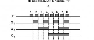
Let's say we have a transformer that has a tap from the very middle of the secondary winding. Let's apply an alternating voltage to the primary winding and consider how the voltage will change between the tapping point and the end points of the secondary winding. At moment 1, at the top point there will be a “plus” in relation to the tap, and at the bottom point there will be a “minus”. At moment 2, the voltage between the tap and the end points will be zero. At moment 3, the “plus” and “minus” will change places. If you make more taps from the winding, then the further such a tap is from the first tap and, accordingly, closer to the end of the winding, the more the voltage between it and the first tap will change. At the point of the first withdrawal there is neither excess nor deficiency of electrons. This point is called the “neutral point” (of the secondary winding of the transformer), or neutral. The expression “tension at a (certain) point” is often found in the literature. If you use it, you can say that the voltage at the neutral point is always zero.
The secondary winding of a three-phase transformer is more complex. It consists of three identical windings, which can be connected “in a triangle” (we will not consider this case here) or “in a star”, where the beginnings of the windings are connected together. The point where they are connected is also called the "neutral point".
Requirements for the remote control post
- Indication of the insulation resistance status is “NORMAL” at R > 50 kOhm, “BREAKOUT” at R < 50 kOhm.
- Indication of exceeding the permissible temperature of the transformer.
- Buttons for remote testing of the insulation monitoring system.
A function required for periodic testing of the insulation monitoring system. - Switchable sound signal when any of the monitored parameters goes beyond the normal limits.
Since most medical devices have their own sound alarm (for example, the rhythm of the heartbeat), the sound alarm from the remote control post may interfere with the operation. Personnel, having received information about a transformer overload or a decrease in the network insulation resistance, turns off the sound alarm of the post. - Execution that allows treatment with sanitary solutions.
- Supply and indication voltage no more than 24 V.
What is a network with a grounded neutral and a network with an isolated neutral
A network with a grounded neutral is a network in which the neutral point is connected to the ground either directly or through low resistance. This connection is usually made in a substation. A special conductor is buried in the ground. The size, material of the conductor, burial depth - this is determined by special rules set out in regulatory documents. A separate wire goes from the grounding conductor to the network. It is called PEN - conductor. Translated, this means that this wire is simultaneously
- grounding
- zero worker
What this means will be explained below.
If the neutral point is not connected to ground or is connected through a large resistance, then such a network is called a network with an isolated neutral. In such a network (here we are considering networks with voltages up to 1000 Volts) there may also be a grounding wire. Since it is only grounding, it is called PE - conductor (without N). Explanation below.
If the voltage in the network is less than 1000 Volts (for example, 380/220 Volts) and there are no transformers in the network between the substation transformer and the consumer, then this is a network most likely with a grounded neutral. An exception is networks of enterprises with special operating conditions, for example, mines.
If between the substation transformer and the consumer of electricity there is also a transformer in which the neutral point of the secondary winding is not connected to the ground, then the section from the secondary winding to the consumer is essentially a network with an isolated neutral. Examples are step-down transformers, including in taps, in machine tools, etc.
Operating table lamps
The most stringent requirements are imposed on the supply of power to operating lights. According to regulations, the interruption time of the supply voltage should be no more than 0.5 seconds. and uninterrupted power supply is ensured for at least 3 hours in case of a complete power outage in the event of an accident.
The average power of the lamps is 450 W. There are two options for supply voltage - 220 V 50 Hz or 24 V DC/AC. In the first option, power is supplied from an isolation transformer (RTM-42, clause 2.3.7), powered, in turn, from a UPS with the appropriate battery capacity. In the second option, power is supplied from a specialized UPS (for example ShBP 800-24), which from a cost point of view is significantly cheaper and more reliable.
Grounding in networks with isolated neutral
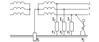
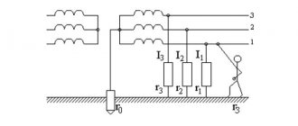
First, let's look at networks with an isolated neutral. In a network with good insulation, leakage currents and capacitive currents occur (Fig. 1). They flow both between phases directly (this is not shown in Fig. 1) and through the ground. The magnitude of these currents, however, is small. All electricians must remember the permissible insulation resistance value - at least 0.5 Mohm. The current at a voltage of 220 volts and a resistance of 0.5 MΩ will be 0.00044 A. Half a thousandth of an ampere.
However, leakage currents (and capacitive ones) can cause damage, and even death, if a person touches a phase wire (Fig. 2). The higher the network voltage, the more dangerous such currents are.
What happens if the insulation is broken in one place in the circuit and a short circuit occurs? A short circuit either to ground or to a metal structure (support, motor housing, lamp housing, distribution cabinet housing, etc.) connected to ground. Let us assume that in other places the insulation is intact (Fig. 3). There will be currents through leakage resistances and capacitances.
If, during such a short circuit, a person standing on the ground touches another phase, it will be mortally dangerous for him - he will be under linear voltage, that is, under voltage between two phases (Fig. 4).
What happens if another phase shorts to ground in another place? Current will flow between the phases (Fig. 5). Protection may work. Or it might not work. It may not work right away. This will depend on the magnitude of the current. And the magnitude of the current depends on the resistance of the earth, which can be very different, differ by orders of magnitude depending on humidity, freezing, soil composition (sand, clay or rock), etc. For a person exposed to such a current, this is deadly . And even if it does not touch the shorted conductors, it can be subject to step voltage.
To avoid such a danger, protective grounding is done. Metal structures that can come under voltage are electrically connected to a conductor that is connected to the Earth. Just as in networks with a grounded neutral, it is usually connected to the Earth in a substation. According to special rules, a special piece of iron is buried in the ground and connected to a grounding wire.
What happens in a situation like in Figure 5, but if there is a protective ground? Look at Fig. 6 The fault current will flow through the grounding conductor. Current will also flow through the ground, but its magnitude will be much less than in Fig. 5. The total current will be large and therefore the protection will operate. For the protection to work, the resistance of the grounding conductor must be low enough. It should be thick enough so as not to burn out from high current.
Why do you need to connect the protective wire to ground? What does this give? Maybe it’s enough to simply connect the metal structures to each other with a conductor for the protection to work? The ground is an additional protective conductor (if the metal structures are connected to the ground), and in the event of a break in the main (protective conductor), it is the only one, although not very reliable (Fig. 5) This is how I understand it.
Classification of premises
According to IEC 60364-7-710.2001, depending on the type of medical procedures performed in the premises, the following classification of premises is provided:
- Gr 0 - med. rooms where electrical appliances are not used;
- Gr 1 - med. rooms where devices are used externally or internally, but a power failure cannot lead to death or serious damage to the life of the patient;
- Gr 2 - premises where a primary fault in the power supply circuit should not lead to failure of life support equipment.
Group 2 rooms include: operating rooms, intensive care rooms, anesthesia rooms, preoperative preparation rooms, postoperative recovery rooms, artificial heart rooms and rooms with children born prematurely.
To power electrical appliances in the premises of medical institutions, Group 2, in order to ensure maximum electrical safety, the use of isolation transformers with a network insulation monitoring system (isolated neutral mode or IT network) is prescribed.
Grounding in networks with grounded neutral
Now let's move on to networks with a grounded neutral. What will happen if a person standing on the ground touches a phase wire in such a network (Fig. 7)? This is deadly. Although the voltage it will come under will be phase-to-phase (that is, if the voltage between phases is 380 V, the person will come under 220 V), the current flowing through it can be very large. The strength of the current and, accordingly, the degree of damage will depend on the resistance of the circuit.
The situation is also dangerous when a phase wire shorts to the ground or to a metal structure connected to the ground (Fig. 8). Compare Figure 8 with Figure 5. What do the situations depicted have in common? A large current passes through a person, depending on the resistance of the earth. Step tension is generated. The defense may or may not work. In Fig. 5 people find themselves under line voltage, and in Fig. 8 under phase voltage, but you can also die from phase voltage.
Now let's see what happens during a short circuit if protective grounding is performed (Fig. 9). Again, compare Figures 9 and 6. There are two purposes of protective grounding: 1. In the event of a short circuit, trigger the protection (protective shutdown) 2. Reduce the voltage and current that a person may be exposed to in the event of an insulation failure and short circuit.
The term (protective) nullification occurs. What do you mean by this? Grounding refers to the electrical connection to the neutral of the transformer. See Figure 9. It shows grounding, and since the neutral of the transformer is grounded, it is also a protective ground. In networks with an isolated neutral, grounding is not used. Why? It would greatly worsen the security situation. Why, I won’t write in detail; this is written about in Nayfeld’s manual. If in such a network, along with grounding, grounding were used, then we would have a network with a grounded neutral. as in Figure 9. It would lack the benefits of an isolated neutral network.
Repeated or additional grounding is often performed (Fig. 10). To quote Nayfeld: “Additional grounding does not worsen, but often improves the safety of networks and electrical installations.” When closed, it reduces the current on the neutral conductor, reduces the step voltage, and promotes faster response of the protection. For re-grounding, natural grounding agents are often used - pipelines laid in the ground, metal structures connected to the ground, and outer sheaths of cables.
Let me quote from the PUE: “1.7.61. When using the TN system, it is recommended to re-ground the PE and PEN conductors at the entrance to the electrical installations of buildings, as well as in other accessible places. For re-grounding, natural grounding should be used first. The resistance of the re-grounding electrode is not standardized.”
The meaning of the terms TN, PE, PEN is described below. What can and cannot be used as a natural grounding conductor, this is stated in PUE 1.7.109 and 1.7.110.
It is important to remember that it is unacceptable to perform additional grounding and at the same time disconnect from the main grounding wire. Why? Look at Fig. 11. In this case, during a short circuit, the protective shutdown may not work, since, as I have already explained, the ground resistance can be very different.
However, the PUE is allowed to use a grounding system that is not electrically connected to the grounded neutral of the transformer (Fig. 11-1). This system is called TT. It is only permitted in cases where electrical safety conditions in a TN system (that is, when grounded in the manner shown in Figure 9) cannot be ensured. An example of such a case is the network feeding a construction site. As a rule, the network is temporary, its reliability often leaves much to be desired. Therefore, it is allowed not to pull a PEN conductor to the construction site, but to make grounding next to it - bury (hammer) a piece of hardware into the ground (how and which one is determined by the rules) and connect the housings of electrical construction machines and mechanisms to it. In the TT system, the use of an RCD is mandatory.
I will quote PUE 1.7.57. “Electrical installations with voltages up to 1 kV of residential, public and industrial buildings and outdoor installations should, as a rule, receive power from a source with a solidly grounded neutral using a TN system.”
Therefore, the vast majority of 380/220 V networks in our cities, villages and enterprises are networks with a grounded neutral.
Types of grounding systems
Have you noticed that the neutral wire in a three-phase cable has a smaller cross-section than the rest? This is understandable, because it does not bear the entire load, but only the current difference between the phases. There must be at least one grounding loop in the network, and it is usually located next to the current source: a transformer at a substation. Here the system requires mandatory grounding, but at the same time the neutral conductor ceases to be protective: what happens if a “zero burns out” in a transformer transformer is familiar to many. For this reason, there may be several grounding loops along the entire length of the power line, and this is usually the case.
Of course, repeated grounding, unlike grounding, is not at all necessary, but is often extremely useful. Depending on where the general and repeated grounding of the three-phase network is performed, several types of systems are distinguished.
Difference between grounding and neutralizing
In systems called IT or TT, the protective conductor is always taken regardless of the source. To do this, the consumer arranges his own circuit. Even if the source has its own grounding point to which the neutral conductor is connected, the latter does not have a protective function. It does not contact the consumer’s protective circuit in any way.
Systems without grounding on the consumer side are more common. In them, the protective conductor is transferred from the source to the consumer, including through the neutral wire. Such schemes are designated by the prefix TN and one of three postfixes:
- TN-C: the protective and neutral conductors are combined, all grounding contacts on the sockets are connected to the neutral wire.
- TN-S: The protective and neutral conductors do not contact anywhere, but can be connected to the same circuit.
- TN-CS: the protective conductor follows from the current source itself, but is still connected there to the neutral wire.
Key points of electrical installation
So how can all this information be useful in practice? Schemes with the consumer’s own grounding are naturally preferable, but sometimes they are technically impossible to implement. For example, in high-rise apartments or on rocky ground. You should be aware that when combining neutral and protective conductors in one wire (called PEN), the safety of people is not a priority. Therefore, equipment with which people come into contact must have differential protection.
And here, novice installers make a whole bunch of mistakes. Incorrectly determining the type of grounding/zeroing system and, accordingly, incorrectly connecting the RCD. In systems with a combined conductor, the RCD can be installed at any point, but always after the point of combination. This error often occurs when working with TN-C and TN-CS systems. And especially often if in such systems the neutral and protective conductors do not have appropriate markings.
Difference between grounding and neutralizing
Therefore, never use yellow-green wires where it is not necessary. Always ground metal cabinets and equipment housings, but not with a combined PEN conductor. When the zero breaks, a dangerous potential arises on it. This must be done with a PE protective conductor, which is connected to its own circuit.
By the way, if you have your own circuit, performing unprotected zeroing on it is very, very not recommended. Unless it's your own substation or generator circuit. The fact is that if the zero is broken, the entire difference in the asynchronous load in the citywide network will flow into the ground through your circuit, heating up the connecting wire.
Protective grounding. What are the dangers of doing grounding yourself?
The operating principle of grounding for buildings according to the TN-C, TN-S and TN-CS systems.
Grounding the house. Installation of the ground loop!
Ground loop. Grounding and zeroing at objects.
We will be glad if you subscribe to our Blog!
But how to determine which network, with an isolated or grounded neutral?
A network with an isolated neutral does not have a neutral working wire, but does have a grounding wire. If the network is working properly, the grounding conductor is not electrically directly connected to the phase conductors (although it may be connected through devices with high resistance). In networks with a grounded neutral, as a rule, although not always, 4 wires (cable cores) come from the substation to distribution points (panelboards, cabinets) - 3 phase and one grounding wire, also known as the neutral wire (this wire is called a PEN conductor) . The PEN conductor usually comes on a bus, which is connected to the panel or cabinet body and to which both neutral working and grounding wires are connected. Next, the neutral working wire is a separate conductor (it is also called an N-conductor), and the grounding wire is a separate conductor (PE conductor). Often the PEN conductor goes further and branches into a neutral working and grounding conductor at a lower level distribution point, for example, a floor panel.
The ground wire is also called the neutral protective wire, in contrast to the zero working wire. Both the neutral working and grounding wires have an electrical connection with the phase wires both through the transformer winding and through the load, for example, lamps. The resistance between them is low. In general, if the network has consumers operating from “phase” and “zero” (which can be checked, for example, by a voltage indicator on a working outlet), then this is a network with a grounded neutral. If the network has both a neutral working wire and a grounding wire, then this is a network with a grounded neutral.
PUE requirements
In the Rules, Chapter 1.7 is devoted to the standards and requirements for solidly grounded systems; we present the most significant excerpts from it:
- To connect the neutral to the ground loop, you must use a special conductor.
- When choosing a location for a grounding device, you should proceed from the minimum permissible distance between it and the neutral.
- If a reinforced concrete foundation structure is used as grounding, then it should be connected to its reinforcing base at at least 2 points, this guarantees the most effective protection.
- The resistance of the grounding conductor for a three-phase electrical network circuit of 0.4 kV is limited to 4 Ohms. In exceptional cases, this standard may be revised based on the characteristics of the soil.
- It is prohibited to install fuses, protective devices and other elements that could compromise the integrity of the conductor in a solidly grounded neutral line.
- The rules require that the grounding conductor be provided with reliable protection from mechanical damage.
- The overhead line must be equipped with redundant grounding switches; they are installed at the beginning and end of the line, on branches, and also every 200 m.
- Duplicate grounding must also be carried out at the consumer input and must be indicated in the ASU panel diagram.
- When organizing household single-phase networks from the ASU, wiring must be carried out with three wires, one of which is phase, the second is zero (N) and the third is protective (PE).
- The response speed of circuit breakers installed in single-phase networks with a solidly grounded neutral should not last longer than 0.40 seconds.
How not to ground.
The ground wire should not go through the switch (Fig. 12). It may be accidentally switched off, rendering the grounding inoperative. It is also unacceptable to connect grounding through a fuse.
In Fig. Figure 13 shows what can happen if the ground is made as a branch of the neutral working wire. If the neutral wire is broken or burns out before such a branch
, an object grounded in this way will be energized.
But what if there is no separate grounding wire (in old networks)? Nayfeld's manual gives the correct grounding option, as in Figure 13-1. That is, grounding (it would be more correct to call it protective grounding) is taken from the common neutral working wire. However, if it burns out, the housing will again be under voltage. However, as I understand it (I’m not sure if I’m right), this solution complies with modern rules (Regulations for the construction of grounding networks 7.21, 10.10.10, read for yourself). Let's say you bought a chandelier with a clamp for the grounding wire, but in your old apartment the grounding wire does not stick out from the ceiling. 7.21 and 10.10.10 prohibit grounding (zeroing) the chandelier from the neutral working wire. According to the rules, you must extend the grounding wire (or neutral protective wire) from the branch box, panel, where (in the absence of a grounding wire) you can power it from the neutral working wire. Those who do not want to do this can justify themselves by the fact that “The standards apply to all newly constructed and reconstructed electrical installations” (PUE 1.1.1, Standards for the construction of grounding networks 1.1) and not ground the chandelier.
Typically, the neutral working and grounding wires are branched from the common wire (PEN conductor) in electrical panels (panels, cabinets). It is prohibited to electrically connect the neutral working and grounding wires after they have branched from the common wire (Fig. 13-2). (PUE 1.7.135.) Why?
Because then the operating current (as well as the short circuit current, if one happens) will flow not only through the zero operating current, but also through the grounding wire. If the housings of electrical equipment are connected to ground, some current, perhaps negligible, will flow through them to ground (Fig. 13-0-3). Equipment enclosures may be under voltage (perhaps negligibly, and possibly noticeably). Let’s assume that in such a situation, either the zero working wire or the grounding wire has failed (burnt out, broken) (wires often burn out at the connection points). Perhaps we won’t even know about it, because instead of the failed one, the remaining wire will work for us. Some might think this is good.
But what happens if the remaining wire subsequently fails? Let's look at another case first. Let's say the neutral and ground are not connected, and the neutral wire has burned out. (Fig. 13-0-1) By the way, since the workload passes through them, the neutral wires burn out much more often than the ground wires.
The network will experience a so-called “phase imbalance” - unevenness of the phase voltage, proportional to the unevenness of the load. (Load unevenness is when the total powers of consumers powered from different phases differ from each other). Single-phase equipment (such as light fixtures) can be exposed to either very high or very low voltage and fail. Three-phase equipment can also fail due to uneven voltage.
Now consider the case when zero and ground are connected by a jumper, and both of them are burned out. (Fig. 13-0-2) Find the differences from the previous picture. We have one more “pleasure”. The equipment housings will be energized (through the load). The magnitude of this voltage will depend on the unevenness of the load. The voltage will be highest if in such a situation there is a single-phase section of the network, for example, an apartment. This is if we do not have a short circuit (to the body or to the neutral wire).
What if a short circuit occurs due to which one of the wires (neutral or ground) burns out, and the other wire has already burned out earlier, or they both burn out? Then our cases will be under phase voltage (220 V), and single-phase equipment, powered from two of the three phases, will be under line voltage (380 V). See Figure 13-0.
Many visitors to this page complain about voltage on the ground wire. Let me clarify: the voltage between the grounding wire and the Earth’s potential, which may have, for example, water supply or heating pipes. This voltage can be shown by a capacitive voltage indicator - a screwdriver.
One of the possible reasons for this is the jumper between the zero working and ground wires, which I described above.
Another reason is the use of the ground wire as a neutral wire, possibly in combination with a break in the ground wire or poor contact of its connection. If all 220 volts are on the grounding wire , this is a dangerous matter, do not touch the housings
- a break (burnout) of the grounding wire in combination with a phase short circuit to it or to the housing is likely.
I will describe one more reason in more detail. As you know, any conductor has resistance. When current passes through it, a voltage drop occurs in it, proportional to the share of the conductor resistance in the total resistance of the circuit. This drop can be measured by connecting a voltmeter to the two ends of the conductor. If the conductor resistance is low (for example, it is a relatively thick and short cable), then the voltage drop is low. If it is large (for example, it is a long and thin wire of an overhead line), then the drop is large. This situation often happens in networks powered by overhead lines. Look at fig. 13-0-4 Let’s say that before the branching, the common neutral (grounding) wire (PEN - conductor) goes from the substation with an aluminum wire along poles across five streets. The resistance of this wire is relatively high. As a result, phase imbalance and voltage on the grounding wire and grounded housings are possible. By the way, the resistance of the phase wires of the overhead line will be just as high, because they go along the same poles, and, as a rule, have the same thickness. A
more uniform distribution of the load across the phases, as well as additional (repeated) grounding, can help here. PUE (1.7.102) prescribes it to be done at the ends of overhead lines and branches from them with a length of more than 200 meters.
Requirements for an isolation transformer
- The power of isolation transformers is limited to the range of 0.5-10 kVA, for both single-phase and three-phase transformers.
This requirement is due to the fact that control over many consumers in a highly branched distribution network is less effective. The occurrence of an accident or insulation failure in any part can lead to a general network failure and makes it difficult to locate the fault location. Related to this is the regulatory requirement that determines the power supply of each operating room from one transformer (RTM-42). - The output voltage of the three-phase isolation transformer is 3 f 220V.
The presence of 380 V line voltage in a room with medical equipment is prohibited, as it is a factor that reduces the electrical safety of the room (IEC 60364-7-710, Instruction RTM-42).Connection of consumers to a three-phase transformer is carried out according to the diagram shown in Fig. 3.
The use of a three-phase transformer requires an appropriate distribution network arrangement, since the neutral wire is not used.
- The presence of a shielding winding is required.
This requirement reduces the likelihood of insulation breakdown between the primary and secondary networks in the event of a transformer failure and significantly reduces leakage currents caused by “stray” capacitance between the windings. Thirdly, an isolation transformer with a shielding winding is a good filter for high-frequency interference, which has a very positive effect on the operation of the equipment. - Increased requirements for transformer insulation that meet medical standards.
For example, the test voltage between windings and windings and housing is 4150 V. - Soft start system.
Mandatory requirement of GOST 30030. The inrush current of a conventional transformer is from 5 to 8 times the operating current, which can trigger standard circuit breakers on the supply side and affect the operation of third-party equipment, initiating a short-term dip in the supply voltage. - The deviation of the output voltage at idle and under load is no more than 5% of U VX.
- Increased load capacity.
- Mandatory temperature control of windings.
By measuring these parameters, personnel receive operational information about network congestion and take the necessary measures (for example, turning off unused loads). - Insulation monitoring system (IMC).
- Remote control output (alarm) about exceeding the load level and temperature.
- Transformer remote control post (RTM).
What happens if you mix up the neutral working and grounding wires?
I wrote above that there may be voltage on the neutral working wire. This stress will end up on your body. The operating current will flow through the grounding wire, which will create a (possibly negligible) voltage on it and on the cases that are properly grounded. The likelihood of the ground wire burning out will also increase. If it burns out, the voltage will be on the housings that are properly grounded.
Here is another example of the consequences of improper grounding (Fig. 13-3). The left lamp is grounded (incorrectly) from the neutral working wire, the right one is grounded from the ground wire. Let's say our neutral main wire has burned out. Then our current will flow as follows: from the phase through the lamps to the neutral wire, then through the incorrect grounding of the first lamp to its body, then along the circuit on which the lamp hangs, along the beam, again along the circuit to the body of the second lamp and further into the grounding wire . The light will be on. But if you move the chains on which the lamps hang, they will spark, and even shock you. I have encountered this situation often.
Grounding should not be done in series.
Connection using low resistance
Among the many types of neutrals, grounding through a resistor with a small nominal value is often used. They have found wide application in Belarus and Russia. It is logical to use a high-resistance resistor (RB-mode) in such circuits, which sets low levels of overvoltages during short-term protection.
In other cases, when grounding the neutral point, combined methods of connecting it through the use of inductance (RB mode and LB mode) are used.
A more detailed study of the indicated approaches shows that high-resistance type resistors are characterized by impressive sizes. In addition, they differ in significant prices and weight. However, the design of arc suppression reactors has its own characteristics and disadvantages. Therefore, when choosing a mode supported by a low-resistance resistor, careful calculations and calculations should be made taking into account the indicated factors.
There are two types of low grounding. In the first case, a resonant resistor device is installed, with the help of which the protection against currents during short circuit protection is triggered. As for the second option, it involves the use of grounded circuits through inductance. They are aimed at providing protection in the event of phase double faults.
When using a resistive connection, it is worth taking into account additional currents in the neutral, which can cause interruption of the capacitive values of the SGC up to 3 times or more. Inductive or reactive circuits in terms of their grounding level should not exceed the total value of electric currents emanating from double circuits
Based on the PUE, the operating modes indicated above can be short-term or long-term. The latter option involves the arrangement of grounding parts in a single circuit in which the neutral functions on a permanent basis.
It is this method of connection, as indicated by the rules for the construction of electrical installations, that is permissible only when performing high-quality grounding with an indicator RЗ ≤ 0.5 Ohm. This approach is effective in terms of labor costs and economic considerations.
Meanings of some terms
The meanings of the terms are explained in detail in the PUE and the Standards for the Construction of Grounding Networks.
What do the terms “TT, TN, IT grounding system”, etc. mean? If the first letter in these abbreviations is “T” (from the word “terra” - earth), then this is a system with a grounded neutral, if “I”, then with an isolated neutral. If the second letter is "T" (eg "TT"), then exposed conductive parts (eg housings) are grounded but not connected to the neutral. If the second letter is “N”, then the exposed conductive parts are connected to a solidly grounded neutral. The third and subsequent letters, if any (for example, “TN-S”) mean whether the neutral working and neutral protective (that is, grounding) conductors are separated or combined in one wire. If the third letter is “S” (from the word “separate” - separate), then each of these conductors runs as a separate wire throughout the system. If “C” (“common” is common), then they are combined in one wire. If "CS" (for example, "TN-CS"), then the common (neutral and ground) wire is then branched.
What do the terms “N-conductor, PE-conductor, PEN-conductor” mean? N—zero worker; PE - zero protective (grounding); PEN - combined zero working and protective.
What is potential equalization and why is it needed?
If there is a potential difference (voltage) and a conducting medium (for example, the human body) between two points, then a current will flow between them. The current can cause injury to a person, sparking, which will lead to fire and other harmful consequences. To avoid this, potential equalization is performed: parts of equipment, buildings and structures are either connected with a special conductor, or their current-carrying structures themselves are reliably connected to each other. They are also connected to the grounding (neutral) wire. Potential equalization is considered a measure complementary to grounding. How and in what cases to carry it out is written about in the Standards for the Construction of Grounding Networks (10-11-40, 10-12-3 and other sections).
Features of an effectively grounded neutral
According to PTEEP, the maximum permissible resistance value of a grounding device for networks with an effectively grounded neutral (for electrical installations above 1000 V and with a large ground fault current - over 500 A - for each object) is 0.5 Ohm, taking into account natural grounding (with the resistance of an artificial grounding device - no more than 1 Ohm). This is caused by the need to pass significant currents during a short circuit. to the ground, high and ultra-high voltage network, the requirement to limit the voltage between the ground and undamaged phases, as well as the possibility of high touch voltages, step voltages and dangerous “removal of potentials” beyond the territory of the substation during accidents. The need for uniform distribution of potentials inside the substation and the elimination of the appearance of step voltages at a considerable distance from the substation is excluded by the so-called. potential equalization device, which is an integral part of the grounding device for effectively grounded neutrals. Special requirements for grounding devices with effectively grounded neutrals create significant difficulties for their calculation and construction, making them material-intensive, especially for soils with high resistivity (rocky, rocky, sandy soils) and cramped construction conditions.
Read Nayfeld, PUE, as well as Standards for the construction of grounding networks. Everything is more precise and detailed there.
- In particular, in the 7th edition of the PUE it is written:
- 1.7.101 What should be the resistance of the grounding device
- 1.7.102 About re-grounding overhead lines>
- 1.7.109 What can be used as natural grounding conductors.
- 1.7.110 What cannot be used as natural grounding conductors.
- 1.7.113 and 1.7.117 Sections of grounding conductors in electrical installations with voltage up to 1 kV
- 1.7.119 and 1.7.120 Main grounding bus
- 1.7.121 - 130 Standards governing grounding conductors (PE conductors)
- 1.7.121 - 131-135 Standards governing PEN conductors
- 1.7.142. Connections of grounding conductors
- Among other things, the Standards for the Construction of Grounding Networks state:
- 1.3.1.1 Basic rule for electrical installations
- 1.3.1. Grounding of electrical equipment installed on overhead line supports
- 1.4. Using Natural Grounding Devices
- 1.5. Combining grounding devices
- 1.11. Application of RCD-D as additional protection in electrical installations up to 1 kV
- Chapter 2 How potential equalization is performed.
- 2.6.1 What is subject to grounding or zeroing
- 2.7.1 What does not need to be grounded or neutralized
- Chapter 5 electrical installations with voltage up to 1 kV network with a grounded neutral (TN system)
- 5.18 - 5.20 Grounding overhead lines
- 7.1 - 7.6 What can be used as grounding and combined conductors
- 7.7 The need to ground support cables, cable armor and metal hoses
- 8.1 Natural ground electrodes
- 8.10 Artificial ground electrodes
- 8.25. Connection of parts of the grounding conductor, connection of grounding conductors with grounding conductors
- 10.1.2. Grounding current transformers
- 10.2 Grounding cables
- 10.3 Grounding overhead lines
- 10.4 Grounding of electrical machines
- 10.5 Grounding of individual devices, panels, cabinets, boxes with electrical equipment
- 10.5.4. It is prohibited to connect more than two cable lugs to one neutralizing bolt (screw).
- 10.9 Grounding of portable electrical receivers
- 10.10 Electric lighting
- 10.10.4 In group lines supplying general lighting fixtures and plug sockets, the neutral working and neutral protective conductors are not allowed to be connected to a common contact terminal
- 10.11 Electrical installations of residential, public, administrative and domestic buildings
- 11/10/14. In buildings, cables and wires with copper conductors should be used.
- 10-11-24 to 10-11-39 RCD in buildings
- 10-11-40 potential equalization system in buildings
- 10-12 Rooms containing a bath or shower
- 10-13 Rooms containing sauna heaters
- 10-18 Lightning protection
Frequently asked questions:
Equipment placement
The principle of placing electrical equipment is quite standard, but special attention should be paid to the location of the transformer remote control post (RTM). It is necessary to place it in the personnel work area to quickly obtain information about the state of the IT network and transformer.
When renovating hospitals, a problem often arises with the installation of isolation transformers. In principle, it is permissible to install a transformer in the operating room, but subject to the following condition: the transformer must be a closed electrical cabinet with a degree of protection IP 54 with the ability to treat it with sanitary solutions.
In Fig. Figure 5 shows an example of a typical and practice-tested diagram for connecting operating room life support consoles to a three-phase isolation transformer with a power of 6 kVA (overload capacity up to 10 kVA within 30 minutes). The specified ratings of the machines ensure stable operation of the system and a maximum load power of up to 3.5 kVA per outlet.
Why is the neutral wire thinner than the phase wires?
The neutral wire is made thinner than the phase wires, because the current that flows through it is less than the current that flows through the phase wires.
If the load across the phases in the network is distributed (strictly) evenly, the currents in it flow from phase wires to other phase wires. The voltage drop in the network will be such that the neutral potential will be on the neutral bus and the current in the neutral wire will be zero. When the loads are uneven, a current appears in the neutral wire. The greater the unevenness, the larger it is.
Why is a neutral wire needed?
I wrote above that the neutral and grounding conductors usually come from the substation in one wire, and why a grounding wire is needed. Now about the function of the neutral working wire. It is needed to avoid the “phase imbalance” that I described above. Although electricians strive to achieve load uniformity (for example, by connecting an equal number of apartments to each phase), unevenness still occurs. You flipped the switch and you have already changed the load ratio. Why is there no “phase imbalance” when there is a neutral wire? Firstly, when many consumers are connected to the neutral wire, load unevenness appears to a much lesser extent. When you turn on the TV to watch football, there is a chance that your neighbors, who are “sitting” on other phases, also turn on their TVs. Secondly, the neutral wire is connected to the neutral. Neutral is a point in the secondary winding of a transformer to which three identical symmetrical windings are connected at one end. At the other end they are connected to the phase wires. Let's assume that the load is distributed evenly across the phases. And suddenly in some phase it increases.
The following will happen:
- The load resistance in this phase will decrease.
- The voltage drop across the load will decrease, and therefore
- The voltage between this phase and zero should decrease, but
- The current in the load will increase, and therefore
- The current in the corresponding third of the secondary winding will increase
- The magnetic field of the secondary winding will increase
- This magnetic field is directed in such a way that it reduces the inductive reactance of the corresponding sector of the primary winding, and therefore
- This inductive reactance will decrease further
- In the primary winding (in its corresponding third) the current will increase, and therefore
- Its magnetic field will strengthen
- This magnetic field will create a higher voltage in the corresponding sector of the secondary winding, and therefore
- The voltage between this phase wire (phase) and neutral (zero) will remain stable
This ensures uniformity of phase voltages.
Why does the neutral wire burn out?
Because current flows through it. It usually burns out in places where connections were made poorly. If the resistance of the connection is high, heat begins to be generated on it. Heat causes the connection to oxidize, its resistance increases even more, and it heats up even more. If the process starts, sooner or later the wire will burn out. Remember this simple wisdom: the larger the contact area, the more reliable the connection. And if a twist 1 cm long burns out in a month, 2 cm in a year, then a twist 5 cm long and longer will last (maybe) forever. Make the twist longer, do you really feel sorry for the wires?
For reliability, you can also twist a piece of uninsulated wire onto the twist.
It’s even better to solder or weld the twist. Nowadays, special caps are used that are screwed onto connections - “PPE”.
By themselves, they only increase the reliability of the connection, but I don’t believe that it’s enough to screw on the PPE and reliability is ensured. Carefully clean the surfaces to be joined (with a file, knife), but not with sandpaper (its grains can worsen the quality of the connection). When making a loop of wire for a bolted (screw) connection, weld it several times with a file (file) so that the contact area is larger. Tighten the screw or bolt until it stops, current will flow through it. Take care that the connection does not weaken over time. Use a good, non-rusty, non-oxidized washer or Grover washer. Do not connect copper and aluminum wires directly, use (steel) clamps for this. Top
Report bugs by email
To home page