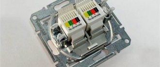
A POE injector is a device for supplying power to the LAN port of network equipment via a twisted pair cable. Data and power are simultaneously transmitted through a single patch cord. This solution is recommended for use in the absence of 220V near the object being connected, that is, a POE injector for IP cameras is considered an excellent option for wired connection of an object at a distance. To connect directly to the injector, the cameras must support POE technology. But there is an option for connecting devices where IP cameras do not need to support POE standards.
POE Standards
What is PoE (Power over Ethernet)? This is a technology designed to power a facility using a single Ethernet cable.
The IEEE 802.3af and 802.3at standards have been used for about ten years to supply power to video surveillance cameras over Ethernet. The updated 802.3at+ appeared in 2013, but did not supplant, but supplemented the already in use POE specifications. The modern 802.3bt standard is aimed at connecting powerful devices like PZT IP cameras that have heating and long-distance IR illumination.
| Standard | Year | Power, W | Cable distance, m | Current strength, A | Voltage, V | Transfer method |
| IEEE 802.3af | 2003 | 15.4 (up to 18) | up to 100 | Up to 0.4 | From 36 to 57 | 1 or 2 |
| IEEE 802.3at | 2009 | 25.5 (up to 30) | up to 100 | Up to 0.6 | From 48 to 57 | 1 or 2 |
| IEEE 802.3at+ | 2013 | 60 and above | up to 100 | Up to 0.6 | 57 | 1 or 2 |
| IEEE 802.3bt | 2017 | 90 | up to 100 | Up to 0.96 | 57 | 1 and 2 |
These standards allow you to save on laying power cables and ensure ease of connection of any PoE-enabled devices. Current transmission occurs in two ways:
- The first is the use of 4 wires for power supply with pinouts 1/2, 3/6. The same as for data transfer.
- The second is the use of 4 unused cores. Pinout 4/5, 7/8.
The 802.3bt standard uses 8 pairs for one IP camera. According to the af and at standards, both methods can be used. This allows you to connect power to two cameras using one four-pair patch cord.
Special equipment will help you interact with power over Ethernet.
Power over Ethernet for IP video surveillance
Parameters for selecting and using power over Ethernet with IP cameras:
- comparison of power over Ethernet (PoE) with power from low-voltage sources,
- when to use PoE and when not to,
- PoE classes,
- comparison of 802.3af with 802.3at and 802.3bt,
- non-standard PoE implementations,
- spare pairs in the UTP cable,
- distance restrictions,
- PoE extenders,
- comparison of energy consumption with specification,
- calculation of energy consumption,
- PoE via switch, mid-injector or NVR.
Comparison of
PoE and Low Voltage Power
All cameras require power to operate.
Power over Ethernet (PoE) technology uses a single cable to connect the camera to the data network and to the power source. Before the advent of PoE technology, connecting cameras to power, in most cases, meant the use of separate low-voltage sources and separate wiring for power supply. PoE technology eliminates the need for a second cable and power supply.
Moreover, when it comes to low voltage power supplies, PoE technology can save between $10 and $30 per camera on power supply, according to various estimates.
PoE is almost always used
PoE technology is supported and used by almost all professional IP cameras and video surveillance equipment.
Exceptions when
PoE is not used
There are a few exceptions when PoE technology with IP cameras is not used. This most often occurs in the case of a fiber optic or wireless backhaul network, where power is provided from a local high-voltage source. Additionally, if powered by solar panels, a lower voltage may be used when directly connected to batteries.
In fact, many budget network cameras today only support PoE, creating logistical challenges in those edge cases where low-voltage power is required.
Types of
PoE
PoE is defined by the following IEEE standards:
- 802.3af, "standard" PoE, used for more than 90% of all IP cameras, provides power up to 15.4 W,
- 802.3at, "high" PoE, is used by a small subset of IP cameras that require power in the 15.4W to 30W range. Most often, 802.3at support is required when using PTZ cameras or cameras with built-in heaters/fans.
- 802.3bt is currently being designed to be capable of delivering 100W of PoE power, which exceeds the requirements of almost all IP cameras.
PoE
Classes PoE can also be divided into classes that segment and more accurately define the power consumption of devices. The following table provides a summary of the types and classes of PoE used in video surveillance.
| PoE type/class | Maximum source power | Maximum power on camera (after 100m) | Usage |
| 802.3af (no class) | 15.4 W | 0.44 - 12.95 W | internal/external cameras |
| 802.3af (class 1) | 4.0 W | 0.44 – 3.84 W | rarely |
| 802.3af (class 2) | 7.0 W | 3.84 – 6.49 W | rarely |
| 802.3af (Class 3) | 15.4 W | 6.49 – 12.95 W | most often |
| 802.3at (Class 4) PoE+, High PoE | 30 W | 12.95 – 25.5 W | PTZ cameras, heated housings |
A formal PoE specification must contain both a type and a class, but this requirement is usually ignored. Most often, PoE is defined as “802.3af” without specifying a class, which means that the source provides power somewhere in the range of 0.44 to 15.4 W.
The class specification limits the minimum and maximum power that can be provided. For example, if the power is specified as 802.3af Class 2, this means that the maximum possible power is 7.0 W.
While knowing the type and class nomenclature is important, most modern power supplies and PoE devices are unclassified and this designation is becoming increasingly rare.
802.3bt on the horizon
An even more robust PoE class (802.3bt), currently in draft and early development, is expected to be adopted in 2022. This project offers a PoE option capable of delivering 100W of power at the source by using all four pairs of the appropriate category cable, more information on this is provided in the next section. While the prospect of more than doubling the power of 802.3at is exciting, its use in video surveillance equipment may not be necessary.
The most likely applications for 802.3bt are lighting systems, electrically driven control devices, security systems, and high-power industrial sensors. Most network video cameras require less than 10 watts to operate successfully.
PoE
implementations Not all PoE devices use the 802.3at/af standard. In video surveillance systems, there are separate private implementations of this basic idea, differing in voltage or power. If a PoE product is not specifically specified to comply with the 802.3af/at standard, incompatibility issues may arise.
In some cases, proprietary PoE implementations work according to the standards, but with reduced functionality. The 802.3af/at standard uses a passive format in which power is provided on unused pairs, but it is possible to provide power in an active format on pairs used for data transmission.
One example: Some versions of Ubiquiti products use 24 VDC PoE rather than the 48 VDC standard. Although in reality an Ethernet cable is used for power, it must be supplied using a non-standard PoE injector.
Comparison of Alternative
A and Alternative B
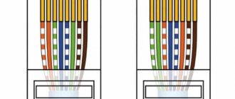
So, how does PoE work? To answer this question, you need to take a closer look at a typical RJ-45/8P8C connector and UTP cable. The table below shows that of the eight wires in a Category 5/5e/6 cable, only four are typically used. The remaining four remain unused. Alternative A (Passive PoE) supplies power over the pairs used for data transmission, while Alternative B uses unused wires to supply power to the connected device. The following table shows the pinout layout of Alternative B:
In the case of Alternative B, two pins of the standard 8-pin connector are used to transmit data, two are used to receive data, two are used to supply DC positive, and the remaining two complete the circuit, connecting to DC negative.
However, most IP video surveillance systems automatically detect which pairs are used for power supply.
Although pinouts vary depending on cabling standards (such as TIA/EIA 568A or B), the standards only apply to the two pairs used for data transmission and do not affect the pairs used for power supply. Regardless of which wiring standard is used, as long as the power supplies and devices comply with the 802.3af/at specification, the power connections are the same.
Distance restrictions
PoE is limited to the same 100m as Ethernet networks in general. First, the quality of data transmission is lost, and only then the power characteristics drop below those guaranteed by the standards.
Some manufacturers have adopted a power supply option that involves connecting a number of cameras in series.
PoE
extenders To provide power over distances greater than 100 m, PoE extenders are used. They are usually pairs of adapters for each network video camera with power supply on the head end side. PoE extenders can provide power over a distance of 300 or even 600 m.
Comparing
PoE Power Consumption to Specifications
IP camera manufacturers list power consumption along with whether their cameras support PoE. This information is necessary to know the total power, since even if all cameras are of the “regular” 802.3af PoE standard, power consumption can vary from 2 to 15 W. As a rough estimate, fixed IP cameras typically consume around 4 – 7 Watts.
In the specifications of network video cameras, power consumption values are usually indicated with a margin and exceed actual power consumption, this is confirmed by testing of IP cameras that support PoE.
Energy consumption calculation
Typically, multiple IP cameras are powered by a single device. Thus, it is necessary to know the energy needs of each chamber and summarize them when combining them into one system.
The following table shows an example calculation for 7 cameras of 3 models.
| Quantity | Camera model | PoE power consumption | Total consumption |
| 2 | Axis Q1604 | 7 W | 2 x 7 = 14 W |
| 2 | Bosch Starlight 7000 HD PTZ | 24 W | 2 x 24 = 48 W |
| 3 | Dahua HF3101N | 6 W | 3 x 6 = 18 W |
| Total required 80W, 802.3at type | |||
The total power required is 80W, but not all cameras have the same PoE type. While Axis and Dahua cameras consume significantly less than the 15.4W provided by 802.3af, Bosch PTZ cameras require 24W, which places them in the PoE+/802.3at category. For this reason, the power supply must provide PoE+ on at least two ports and a total power of 80 W.
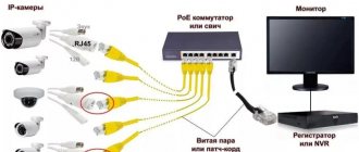
PoE via switch, mid-injector or NVR.
PoE is typically provided in one of three ways:
- from a network switch that supports PoE,
- through a module connected in series to the cable, called an intermediate injector,
- from a network video recorder with a built-in PoE switch.
Most often, a network switch is used to provide PoE. The intermediate injector is used much less frequently, although in some cases it is preferable as it allows switch operation and support to be separated from the intermediate injector/PoE.
Switch problems
The use of PoE is expanding in many areas, and it is not difficult to find switches that support PoE.
However, please note that power must be supplied to all switch ports. Often, especially in budget and consumer switching equipment, PoE is not provided on all, but only on one port or on half of the available ports:
Even many "professional" switches only provide half the power required to fully support 802.3af. For example, 12-port switches often provide 90 W total PoE, which is 7.5 W per port. When connecting IP cameras to all 12 ports, they may require more than 90 W to power them. In such cases, cameras may turn off randomly, which may be mistaken for a malfunction, when in fact it is the switch that is turning off the ports because it does not have enough power to power all the cameras. Some premium switches offer "full" PoE on all ports. For our example with a 12-port switch, the required power would be 180 W (15 W x 12).
Intermediate injectors
Another option, intermediate injectors, is less common but may be the right choice in cases where cameras that support PoE are required but the existing network does not support PoE, or when certain PoE requirements can be met more economically than if purchased more expensively. equipment.
For example, in the 7-camera system example above, two of the cameras place higher PoE+ requirements on the switch. Considering prices, it may be more economical to first purchase a switch that supports regular (802.3af) PoE, and then separately purchase two PoE+ intermediate injectors for PTZ cameras. This move will save you several hundred, so it makes sense to consider both PoE options.
Network Video Recorders
Some NVRs have built-in switches that support PoE. This option is the least frequently encountered and used of the three mentioned. Its main advantage is easier installation, since there is no need to purchase and connect to a separate PoE-enabled switch. There are the same difficulties as in the case of conventional network switches: you also need to check the total power provided, and also pay attention to the power types (PoE or PoE+, etc.) Another difficulty is that network video recorders with The built-in switch can support more video cameras than the number of ports on the built-in switch of this DVR. For example, an NVR might have a built-in 9-port switch and still support 16 cameras. If 16 cameras are required, an additional PoE switch/source will be required.
In the case of DVRs with built-in switches that support PoE, the main concerns are reliability and maintenance of such devices. It is impossible to give an unambiguous assessment, since these devices are not used widely enough or for long enough.
PoE devices
The following equipment is used in the power supply via standard PoE:
- PoE injector - powers network devices via a twisted pair patch cord. It can be used to power a video surveillance camera that operates according to PoE standards.
- PoE splitter - accepts a powered Ethernet cable and branches it into a 12V DC line and a 100 Mbit/s data line.
- PoE extender or extender - increases the distance of information and power transmission using a patch cord for the network.
Injector
The adapter allows PoE consumers to be connected to regular switches. The form factor is different, for example:
- A regular power unit soldered to an adapter.
- The power supply is separate from the adapter.
- Injector built into the power unit.
Diagram for connecting the adapter to the end device with support for the necessary standards.
Splitter
The power and data splitter allows you to connect cameras that do not support power over Ethernet standards. The splitter has a port and two connectors.
The IP CCTV camera connection diagram is standard for all solutions.
Extension
Since signal transmission in a cat.5e network cable (in network construction it is used in 99% of cases) without loss is limited to 100 meters, extenders will allow you to increase the signal transmission line by 100 meters. At the input, the extender receives the signal and repeats at the output exactly as the injector does. Extension cables are not powered separately; they take part of the incoming power via the PoE line (up to 2 W). Therefore, at the output, part of the power is removed, but the length of the communication line increases by 2 times.
The extension cord has a compact body.
Some models allow you to accept 1 line as an input and branch it into two or more. Typically, such extenders are equipped with LED indication and small toggle switches to control the data transmission of each output port.
The connection diagram looks like this.
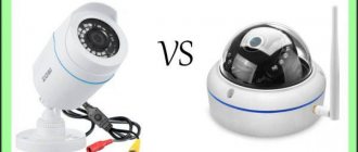
Methods for connecting a video camera
Digital cameras are connected in two ways: with and without PoE technology. It is best to use compatible equipment.
PoE power options
There are several schemes for organizing PoE connections. The composition of the equipment depends on the configuration of the facility.
If the distance between the DVR and the IP camera does not exceed 100 meters, the equipment is connected directly with a UTP cable.
The standard cross-over (zero-hub) pinout of 8-pin RG-45 connectors is used.
| Contact no. | Wire color | Signal type |
| 1 | White-orange | Rx+ network |
| 2 | Orange | Rx network– |
| 3 | White-green | Tx+ network |
| 4 | Blue | +DC 48 V |
| 5 | White-blue | +DC 48 V |
| 6 | Green | Tx network– |
| 7 | White-brown | –DC 48 V |
| 8 | brown | –DC 48 V |
The recorder and camera must support PoE technology.
A distance of more than 100 meters will require the purchase of additional equipment. PoE repeaters are capable of extending the transmission line by 100 m. For distances from 300 to 500 meters, VDSL2 converters are used.
If the power of the recorder ports is not enough, PoE injectors and splitters are used to power the video cameras.
The injector is installed at the location of the recorder or router. The device has connectors for connecting an external power source, “LAN” for connecting a recorder and “PoE” for a UTP cable.
A splitter is mounted on the side of the video camera. A cable from the injector is connected to its input. The device also has two outputs: “LAN” for receiving a video signal and a camera connector.
Where can I buy
You can purchase POE components either in a specialized store or online in an online store. In the second case, the budget option for purchasing products on the Aliexpress website deserves special attention. For some components there is an option for shipment from a warehouse in the Russian Federation; they can be received as quickly as possible; to do this, when ordering, select “Delivery from the Russian Federation”:
| POE cable for IP camera | POE adapter 220V -> (12V 2A), (48V 0.5A) | POE adapter 48V, 2A, 96W |
| POE injector for 4/8 ports | Passive POE injector | POE splitter |
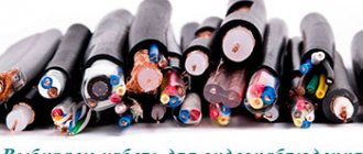
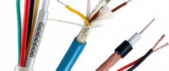
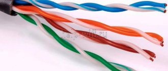
Cable category
The degree of protection against interference also depends on the category of twisted pair.
The higher the category, the higher the protection. Typically, for video surveillance needs, a category 5e cable is used, which, with an optimal price/quality ratio, is capable of transmitting a video signal over a distance of 2-3 thousand meters. For longer distances, higher categories of cables are used that can provide the best protection against interference:
- Thus, a category 8 cable has improved protection against interference due to the presence of an additional shielding shell that removes interference from the cable;
- To create remote surveillance over distances of 4 thousand meters, it is recommended to use twisted pair cable of category 7 and higher, using powerful active amplifiers;
- Category 5 and 5e cables operate in the frequency range of 100 MHz and 125 MHz, and are capable of transmitting data from cameras at speeds of 100-1000 Mbit/s;
- Categories 6 and 6A operate in the frequency range 250-500 MHz and are used for laying high-speed local networks;
- In a category 7 cable, each pair has a shielded sheath, and there is also a common protective shield under the overall braid. Frequency range – 600-700 MHz, transmission speed 100 Gbit/s.
In analog video surveillance systems, the best cable is the TPPep brand, which is capable of high-quality operation at “high frequencies,” and given that analog cameras have a signal frequency range of 50 Hz - 6 MHz, this point is quite important.
Benefits of PoE Support
The main advantage of equipment supporting power transmission standards is the coordination of voltage and power between supplying and consuming devices. The agreement lasts a fraction of a second. This control check allows you to keep the connected device in working condition without damaging anything.
We recommend reading: calculating and choosing an uninterruptible power supply for video surveillance.
For example, the connector carrying power + data was confused with the connector of a standard Ethernet cable. The power cable connected to the injector was connected to the switch:
- the injector makes a call to the connected device, asking if it needs power;
- the switch does not support PoE standards, so it does not respond to the request;
- the injector understands that it was not possible to establish communication with the final destination and does not transmit power, but only sends data;
- Since no power is supplied, the end device is protected from possible damage.
The second, no less important advantage is the transmission of power over a distance of up to 100 meters without the use of intermediate repeaters. IP cameras are capable of receiving power in the range of 44–57 V. Just within the operating range of the injector. Even if there are voltage drops in the cable, the IP camera will still not turn off.
The third advantage is the transmission of information and power through one patch cord. This significantly saves time and money on laying the power cable.
Fourth, easy power management and control of data transfer using injectors, splitters and extenders. There is also remote control of more advanced (and expensive) injector models via a web interface.
Connecting wires on the DVR
Now all the video surveillance cables need to be disconnected in the low-current cabinet. First, connect the DVR itself via an uninterruptible power supply.
Then you strip the second ends of the KVK-P cable, brought into the cabinet, in the same way as shown above. In this case, connect the power wires (red and black) to the corresponding terminal blocks “+V” and “-V”.
And insert the end of the coaxial cable, with the BNC-F connector installed, into the free socket of the DVR. Where it says Video In.
Do the same with the remaining video cameras.
All you have to do is set up the video surveillance by connecting the monitor to the recorder via VGA or HDMI connectors.
If the low-current cabinet is located far from the computer, you can use a laptop to configure it. And after that, output the signal to the monitor using a separate cable.
To safely use the monitor for other purposes, you can connect a computer to the HDMI connector, and cameras to the VGA connector. Then by changing modes you can easily switch pictures from different sources.
All software for setting up video surveillance must be included with the video cameras. If for some reason it is not there, then you can try universal software, for example from ivideon.
Connecting IP cameras without PoE support
A special analogue of standards for receiving power over a single Ethernet cable has been developed, which is called Passive PoE. The advantage of the scheme is that it can help you save on equipment by purchasing cameras without support for PoE standards. But there is a certain risk.
Since the cameras do not support these standards, this means that testing of the supplied power and power over twisted pair cable is not carried out. Voltage is constantly present in the line, so there is a risk of rapid equipment failure. It may break immediately or after a while due to the constant heating of the board.
A standard passive power connection diagram looks like this.
To ensure this, you need to use a passive injector + splitter combination. If data transfer and power goes to a remote object, an injector + extender + splitter combination is used.
However, the video surveillance camera and switch or router do not support PoE power transmission technologies. DC voltage transmission is transmitted through unoccupied pairs of patch cord conductors (cores 4/5, 7/8).
220V power connection in the low current cabinet
The low-current switchboard, where the DVR, power supply, etc. are located, may be located in a different room from the general 220V switchboard, sometimes even in the garage or basement. Therefore, the first thing you need to do is supply electricity there.
Ditch the walls and lay the VVGnG-Ls 3*1.5mm2 cable from the 220V switchboard to the low-current cabinet. You power it from a separate modular circuit breaker with a rated current of 10A.
In a low-current panel, connect the power cable to the terminals of another circuit breaker. It will be an introductory one for this cabinet. And directly from it you connect modular sockets and a surge arrester.
The arrester is connected according to the diagram below. The white and brown wire is the phase, the blue wire is the neutral wire, and the yellow-green wire is the ground wire.
Connecting sockets:
In the same cabinet there are:
- power unit
- DVR + 1TB disk
- UPS
The hard drive is mounted in the recorder itself. To do this, unscrew the screws and disassemble it. There should be a space inside for the hard drive.
Connect the connectors, and then screw the drive into place.
Please note that often the DVR case is also a cooling radiator for the disk.
Next, you power the UPS from the sockets through a regular plug. Most power supplies come without wires with a plug included, so here you will have to do it yourself. Use PVS wires and a regular Euro plug.
Mount a plug on one end of the wire, strip the other and connect it to the unit at the 220V power terminals, designated L and N.
There is no particular difference in phasing or polarity where to connect zero and phase. Next, connect power to the video cameras.
If there are not enough 12V output terminals on the unit, it is best to use terminal blocks. Set them according to the number of cameras and label the contacts as “+V” and “-V”.
Then, using PuGV wires, connect the 12V +V and -V output terminals from the power supply, with the corresponding connectors on the first terminal block.
It is better to use red wires for the positive wire, and black wires for the negative wire. The remaining terminals are powered by jumpers.
Disadvantages of Passive PoE
Continuous transmission of uncontrolled current to the IP camera is always associated with certain risks:
- The type of voltage transmission and polarity can be any.
- There is no coordination between the source and the connected device. A loss of power to the line will not stop.
- There is no guarantee of voltage transmission over the specified 100 meters.
- The only possible method of transmission is through unused cable cores. That is, connecting only one video surveillance device with one cable.
- Passive PoE control is not possible through the injector. To ensure control, Mikrotik equipment should be installed as a router. In it you can disable the transmission of any data for a specific port.
Installation of video surveillance with analog cameras
Before you directly install video surveillance in your home, you need to draw on paper the locations of video points, cable laying locations, etc.
In order to maximize coverage of the entire space around the house, it is necessary to install at least one camera on each wall. It wouldn’t hurt to put another one on the roof in front of the front door.
Connection and equipment features
List of allowed connection options:
- An 802.3af IP camera can be powered by an 802.3af injector.
- The 802.3af CCTV camera is powered by an 802.3af injector.
- The 802.3af IP camera is powered by a 48 V DC Passive PoE injector.
Prohibited:
- Power the devices using a Cat.5e cable without grounding on both sides.
- Connect an 802.3af standard camera to a 12 V injector.
- Connect the 802.3af video surveillance device to the 24 V injector.
- Pair Cisco equipment with non-native equipment.
Equipment supporting PoE standards
Cameras that support standards include:
- HiWatch DS-I102.
- ORIENT IP-75-MH2DP.
- Trassir TR-D8111IR2.
- HIKVISION 1MP DOME HIWATCH DS-I103 4MM.
- Ginzzu HID-2032S.
Models of injectors, for example, from the company BOLID, which is popular in Moscow:
- PI-154-1 passive, passive 1-port 48V 10/100Mbps.
- PI-154-1B, 1×10/100BASE-T 802.3af, unmanaged budget 15.4W
- PI-154-16M managed 16-port 802.3af 10/100/1000Mbps.