Select the wire diameter required to replace the fuse link
A homemade copper wire fuse can be a great temporary way to replace a blown fuse. But if you decide to do this, then it is extremely important to choose the right cross-section of the very conductor that you will use. Why is this important, what are the reasons for blown fuses and ways to temporarily eliminate this inconvenience we will consider in our article.
General calculation rules
To correctly size fuses, the rated voltage must be taken into account. This value must be such that the fuse breaks the electrical circuit. The main indicator is the minimum expected voltage for the base and fuse.
Another important indicator that must be taken into account when calculating is the cut-off voltage. This parameter represents the instantaneous voltage value that appears after the fuse or fuse itself has burned out. As a rule, the maximum value of this voltage is taken into account.
In addition, the melting current is taken into account, on which the diameter of the wire installed inside depends. When calculating a fuse, this indicator has its own value for each metal and is selected using a table or calculator. The material and dimensions of the inserts must provide the required protective properties. The insert length should not be excessive as this will affect arc extinction and overall temperature performance.
The load power rating is usually stated on the product label. Based on this parameter, the rated current of the fuse is calculated using the formula: Inom = Pmax / U, where Inom is the rated protection current, Pmax is the maximum load power, and U is the supply voltage.
Conclusion
The diameter of the fuse wire depends on the rated current of the product and the material of the wire used. Selecting or calculating this diameter is not so difficult. But such a repair is only a temporary measure.
It is not for nothing that the PUE requires the use of only calibrated inserts, and as for non-separable fuses with a small rated current, their price is not so high as to risk expensive equipment. Therefore, at the first opportunity, be sure to replace the “bug” with a normal fuse or calibrated insert.
Selecting wire diameter and fuse repair
Well, now let’s move on to the main problem of our article – the choice of diameter and the repair itself. Let's start with the first one.
Conductor diameter selection
The diameter of the core in the fuses is clearly calculated. When replacing, it is necessary to install a conductor of the same diameter. Otherwise, the fuse will not perform its function of protecting the electrical network.
- This can be done in several ways. The easiest way is to take the wire size for the fuse, and the table of standard values will allow you to make your choice. To do this, just measure the diameter of the wire.
- The diameter of the wire can be measured with a caliper or even a regular ruler. If the diameter of the fuse wire is too small, measurements can be made as follows. Let's wind the thread around any small object: lighter, pencil, pen.
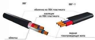
How to choose power wiring
The power cord must be suitable for the system from which it is powered. If the cable is not thick enough, there will be large losses, that is, “waste”, as this phenomenon is now commonly called. This is due to the fact that the cable has resistance, albeit infinitesimal.
it is really very small, about 0.3 - 0.8 Ohm per km of cable length. But it still exists and at high currents in the line the losses can be noticeable.
Selection of cable cross-section
To select a cable of the required cross-section, you do not need to calculate anything. Obviously, you can set the current consumption, the permissible absorption, for example, the current in the system is 100 A, and the absorption does not exceed 0.5 V, and calculate the required cable cross-section taking into account the length of the line. It's not obligatory. There is an old rule of thumb for choosing power cables, which for simplicity is called "five amps per square":
It is based on the fact that the line length from the source to the users (to the amplifiers) does not exceed 5 m. This is 99% of all cases. What does this rule mean? This is normal for current density. With a current density of five amperes per square millimeter, losses on a cable up to 5 meters long will be no more than 0.5 V. In particular, no more than 0.5, this is an important, maximum, non-operating current.
How to use this rule? Take the amplifier and see what its fuse rating is. If there are many of them, consider the total denomination. If you have several amplifiers and are going to power them with one cable, add their preset values. Let's take the result obtained as the maximum current consumption. A real worker will be significantly smaller. We divide the maximum current by 5 and get the required cable cross-section (“5 A per 1 kV mm).
Next, take the next largest standard cable size. We have an Oris TA-150.4 amplifier with a 100A fuse. Typically, the manufacturer provides a margin of 10-20% when choosing a fuse. Accept maximum current 100A. Divide 100 by 5 to get 20 squares. To power such an amplifier, you will need a cable with a cross-section of at least 20 square mm. We choose the following standard cable cross-section: 25 sq. All. To power the Oris TA-150 amplifier.
4, a cable with a cross-section of 25 square millimeters is needed and sufficient. You can use a cable with a larger cross-section, it will not be worse. Will be better? Practice shows that if you take a cable two or more sizes larger, it will definitely not be better. However, losses in the cable tend to zero.
Using the five amps per square rule, select the required wire size or size larger. It is not recommended to buy a thicker cable.
Prosad doesn't just live by cable. And, for example, also on the fuse.
Fuse selection
A power line fuse is mandatory and must be installed near the power source. In an emergency, it must protect the power supply from short circuits. Whatever happened, the cable was frayed and shorted to ground, or the amp burned out and shorted it somehow. The fuse must blow to prevent the wiring from catching fire.
The principle of operation of the fuse is simple and is based on Ohm's law for a closed circuit.
Where Un is the voltage drop between the elements of the system: on the wiring, firstly, on the amplifier itself, etc.
These are all sorts of sags, but we don't call them voltage drops across the amplifier. The magnitude of the voltage drop on the line depends on the resistance of the system element and is always many times less than the voltage drop on the main link, the amplifier. So far everything is good, the losses on the cable and on the fuse are not significant, everything works. Now let’s imagine that some kind of emergency has occurred. Short circuit in the wiring.
Of all the elements of the system connected to the power source (battery), only the power cord and fuse remained (the amplifier fell out of the system). And all its energy will be dissipated directly on the cable and on the front panel. What will burn first, the filament or the first? For a fuse to blow, the drawdown on it must be much greater. This will work stably. Therefore, you need to select a fuse strictly according to the cable.
Not from current consumption, but from cable cross-section.
The fuse rating is also selected in accordance with the “five amperes per square” rule. Only in the opposite direction. Let's say you need to choose a fuse for a cable with a cross-section of 25 squares, which powers the same Oris TA-150.4 amplifier. Multiplying 25 by 5, we get the required power of 125A. The next highest value is 150A.
If the power wiring is selected according to the described rule, the system operates stably, with a good margin, and in the event of a short circuit, the fuse operates clearly. Losses in cables and fuses are very low. Do not bypass the fuse. This is sometimes done in competitions to reduce drawdown. But in everyday life we don’t need this at all.
calculation of power cable and fuse
Many people have questions about selecting a power cable and fuse for their music system. I am posting a table for such calculations and some useful information.
The data in the “Power” column is given for an average amplifier with an efficiency of 50%. When using amplifiers with other efficiencies, pay attention only to the current strength. If the voltage drop exceeds that shown in the table, use the following formula:
L = (0.5 x 57 x A) / (2.5 x I)
Where:
L= cable length, m 0.5 = voltage drop A = cable cross-sectional area, mm2 57 = coefficient for copper cable I = current, A at an effective resistance of 4 ohms 2.5 = loss coefficient
To begin with, I want to say that if two cables from the battery are laid in the power supply circuit of the amplifiers, power supply (+) and grounding (-), and the cable size is calculated correctly (taking into account the table above), this is already a big plus. I note that + and - must be of the same cross-section.
1 Step.
We calculate the cable size based on the requirement - the maximum supply voltage drop should not exceed 0.5 Volts (international requirement), we will assume that everything was done correctly, the cable size of 2 GA with a length of 4.5 meters suits us. The voltage drop at maximum load will not exceed 0.5 Volts.
Step 2
The distance from the positive terminal of the battery to the consumer exceeds 40 centimeters, a fact, so we install a protective fuse, naturally no further than 40 centimeters from the battery terminal, and it is better to install the main fuse as close as possible to the positive terminal of the battery. Its purpose is to protect the power cable from fire, for example in the event of a car accident. The damage to the vehicle may be minor, but a pinched power cable will result in a short circuit, fire, and destruction of the vehicle. The main fuse rating is determined by the MAXIMUM possible fuse rating for a given cable cross-section. For a 2 GA cable, the MAXIMUM possible fuse rating is 150 Amps. Is it possible to install a fuse with a rating of, say, 100 Ampere, 80 Ampere or 50 Ampere? Until then! You can install any fuse, under one condition, that it WILL NOT exceed the nominal value of 150 Amperes (otherwise the meaning of this fuse is lost). The total maximum current that can be drawn by, for example, two amplifiers (an 80A monoblock and a 30A two-channel amplifier) is 110 Amps, so if you install a main fuse rated at 100 Amps, there is a possibility that it will trip at maximum volume peaks, although there are no rules It is prohibited to install a 100 Amp fuse. Based on the above, I recommend choosing a fuse with a rating of 150 Amperes, the rules allow this, in case of an emergency it will work.
Fuse Types
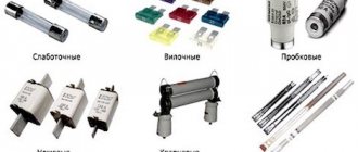
According to their purpose and design, fuses are of the following types:
- Plug (mainly used to protect cables and electrical devices in cars);
- With low-current inserts to protect electrical appliances with current consumption up to 6 amperes;
- Cork (installed in the screens of residential buildings, designed for protection currents up to 63 amperes);
- Knife type (used in industry to protect networks with current consumption up to 1250 amperes);
- Gas generation;
- Quartz.
The repair technology discussed in the article is intended to restore the plug using low-current inserts, plug and blade fuses.
Tubular fuses
A fuse of a tubular design is a glass or ceramic tube, closed at the ends with metal caps, which are connected to each other by a wire of calibrated diameter passing through the inside of the tube. You can see what tubular fuses look like in the photo.
The wire is spot welded or welded to the caps. In fuses designed for very high currents, the cavity inside the tube is often filled with quartz sand.
Automotive fuses
Car fuses rarely fail. Usually only in cases where the equipment fails. Very often when light bulbs near the headlights burn out. The fact is that when the filament of the bulb breaks, a galvanic arc is formed, the filament burns out and shortens, the resistance drops sharply, and the current increases many times over.
It happens that when the wipers jam, the car fuse blows. Less often with short circuits in the wiring. In the photo you can see commonly used car blade guards. Below each fuse is indicated its protection current in amperes.
A blown fuse in a car should be replaced with a fuse of the same rating, but you can also fix it by replacing the blown fuse with a copper wire of the appropriate diameter. The voltage of the car's on-board network does not matter. The main thing is the correspondence of the protection current. If it is difficult to determine the size of a blown circuit breaker, you can use color coding.
Color coding of automotive fuses
Protection current, Ampere Body color fuse orange brown red blue yellow transparent green purple blue black
| 5.0 | 7,5 | 10.0 | 15.0 | 20,0 | 25,0 | 30,0 | 40,0 | 60,0 | 70,0 |
SELECTION OF FUSES, CIRCUIT MEASURES AND CROSS SECTION OF WIRES AND CABLES ACCORDING TO PERMISSIBLE HEATING
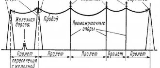
In the event of a short circuit or significant overload, the electrical wiring must be automatically turned off, otherwise the insulation of the wires may ignite, resulting in a fire. Protection devices are designed to automatically switch off wiring when the specified current values are exceeded. In agriculture, fuses are often used for this purpose, the design of which is extremely simple (see Chapter 9). The porcelain case contains conductors of small cross-section - fuse links, connected in series to each phase wire of the line. If the line current increases beyond the permissible limit, the fuse link will burn out, turning off the circuit before the temperature of the wires it protects becomes unacceptably high.
In rural low-voltage networks, two types of fuses are used for internal installation: plug and tubular. Their rated currents in amperes are standardized on the following scale: 4, 6, 15, 20, 25, 35, 50, 60, 80, 100, 125, 160, 200, 225, 260, 300.
Fuses are installed in all places where the cross-section of the conductor towards places of energy consumption decreases, as well as at inputs to buildings and head sections of the network. To ensure that in the event of an accident only the fuse closest to the damage site blows, the rated current of the fuse link of each subsequent fuse from the power source must be at least one step less than the previous one.
The conventional type of fuse is a very imperfect device. The duration of burnout of its fuse link depends on the overload current. At currents 2.5 times higher than the rated current, the new fuse-link burns out relatively quickly (after 8.10 s). The insert can withstand currents 1.5 times greater than the rated current for at least 1 hour, and 1.2 times. 1.3 times - indefinitely. It is impossible to reduce these values and make a new fuse link so that it burns out at lower overloads. The fact is that over time, the fuse link oxidizes, ages and burns out at currents lower than the new one, and can burn out at the rated current or even at current values less than the rated one.
The starting current of short-circuited asynchronous motors used to drive agricultural consumers is 5.7 times higher than the rated one. The start-up duration of such engines reaches 5.10 s or more. If you select a fuse-link based on the rated current of the motor, it will instantly burn out during startup. Therefore, it is necessary to exceed the rated current of the fuse link, which leads to an increase in the cross-section of the wires corresponding to it.
When protecting wires and cables with fuses (except for cables laid in the ground), the calculation of the electrical network begins with the selection of a fuse link. She is selected according to the following rules.
For fuses of the usual type, protecting branches to squirrel-cage asynchronous motors with normal operating conditions (rare starts, run-up duration 5.10 s), a = 2.5. When protecting engines with difficult operating conditions (frequent starts, take-off time up to 40 s) a = 1.6. 2.0.
The maximum current in a circuit with one motor is equal to its starting current. In catalogs, the multiplicity of the motor starting current is usually given as k. Then the maximum current in the circuit
It is obvious that for consumers with small starting currents (asynchronous motors with a wound rotor), a larger value of the fuse-link current can almost always be obtained by rule 1 from expression (5.25).
For consumers whose starting current is almost equal to the operating current (lighting installations, heat consumers), the fuse-link current determined by rule 1 is also always greater than the current found by rule 2.
Having determined the rated current of the fuse-link, select the corresponding wire cross-section depending on whether it will be protected by the fuse-link only from short circuits or also from overloads. According to the rules for the design of electrical installations, it is necessary to protect lighting networks in residential and public buildings, commercial and service premises of industrial enterprises, as well as in fire and explosion hazardous areas from overloads. Networks for any purpose, made with wires with a flammable sheath, must also be protected from overloads when laid open. This applies to networks of any type in hazardous areas. In the listed cases, it is necessary to select such a section so that the following relationship is observed:
Having chosen the wire cross-section, it is also checked using formula (5.31).
Homemade fusible link from a conductor, selection by cross-section
Under no circumstances should you mistake making your own fuses FOR NORMAL. Installation of such products can be considered a TEMPORARY MEASURE.
Diameters of copper wire for fuse
| Diameter, mm | Current, A | Diameter, mm | Current, A |
| Ø 0.05 mm | 0.6 A | Ø 0.71 mm | 47.8 A |
| Ø 0.063 mm | 1.25 A | Ø 0.75 mm | 52 A |
| Ø 0.071 mm | 1.5 A | Ø 0.8 mm | 57.2 A |
| Ø 0.08 mm | 1.8 A | Ø 0.85 mm | 62.7 A |
| Ø 0.09 mm | 2.1 A | Ø 0.9 mm | 68.3 A |
| Ø 0.1 mm | 2.5 A | Ø 0.95 mm | 68.6 A |
| Ø 0.112 mm | 3 A | Ø 1.0 mm | 80 A |
| Ø 0.124 mm | 3.5 A | Ø 1.06 mm | 87.3 A |
| Ø 0.14 mm | 4.2 A | Ø 1.12 mm | 94.8 A |
| Ø 0.16 mm | 5.1 A | Ø 1.18 mm | 102.5 A |
| Ø 0.17 mm | 5.6 A | Ø 1.25 mm | 111.8 A |
| Ø 0.18 mm | 6.1 A | Ø 1.32 mm | 121.3 A |
| Ø 0.2 mm | 7.1 A | Ø 1.4 mm | 132.5 A |
| Ø 0.224 mm | 8.4 A | Ø 1.45 mm | 139.7 A |
| Ø 0.25 mm | 10 A | Ø 1.50 mm | 147 A |
| Ø 0.28 mm | 11.8 A | Ø 1.6 mm | 161.9 A |
| Ø 0.315 mm | 14.1 A | Ø 1.7 mm | 177.3 A |
| Ø 0.335 mm | 15.5 A | Ø 1.8 mm | 193.2 A |
| Ø 0.355 mm | 16.9 A | Ø 1.9 mm | 209.5 A |
| Ø 0.4 mm | 20.2 A | Ø 2.0 mm | 226.2 A |
| Ø 0.45 mm | 24.1 A | Ø 2.12 mm | 247 A |
| Ø 0.5 mm | 28.2 A | Ø 2.24 mm | 268.2 A |
| Ø 0.56 mm | 33.5 A | Ø 2.36 mm | 290 A |
| Ø 0.63 mm | 40 A | Ø 2.5 mm | 316.2 A |
| Ø 0.67 mm | 43.7 A |
For repairing fuses with protection current from 0.25 to 50A
| Current fuse protection, Ampere | 0,25 | 0,5 | 1.0 | 2.0 | 3.0 | 5.0 | 7.0 | 10.0 | 15.0 | 20,0 | 25,0 | 30,0 | 35,0 | 40,0 | 45,0 | 50,0 | |
| Wire diameter, mm | Copper | 0,01 | 0,02 | 0,04 | 0,07 | 0,10 | 0,18 | 0,20 | 0,25 | 0,32 | 0,39 | 0,46 | 0,52 | 0,58 | 0,63 | 0,68 | 0,73 |
| Aluminum | — | — | 0,07 | 0,10 | 0,14 | 0,19 | 0,25 | 0,30 | 0,40 | 0,48 | 0,56 | 0,64 | 0,70 | 0,77 | 0,83 | 0,89 | |
| Steel | — | — | 0,32 | 0,20 | 0,25 | 0,35 | 0,45 | 0,55 | 0,72 | 0,87 | 1,00 | 1,15 | 1,26 | 1,38 | 1,50 | 1,60 | |
| Tin | — | — | 0,18 | 0,28 | 0,38 | 0,53 | 0,66 | 0,85 | 1.02 | 1,33 | 1,56 | 1,77 | 1,95 | 2,14 | 2.30 | 2,45 |
For repairing fuses with protection current from 60 to 300A
| Current fuse protection, Ampere | 60 | 70 | 80 | 90 | 100 | 120 | 160 | 180 | 200 | 225 | 250 | 275 | 300 | |
| Wire diameter, mm | Copper | 0,82 | 0,91 | 1,00 | 1.08 | 1,15 | 1,31 | 1,57 | 1,72 | 1,84 | 1,99 | 1.14 | 2,20 | 2,40 |
| Aluminum | 1,00 | 1,10 | 1,22 | 1,32 | 1,42 | 1,60 | 1,94 | 2,10 | 2,25 | 2,45 | 2,60 | 2,80 | 2,95 | |
| Steel | 1,80 | 2,00 | 2,20 | 2.38 | 2,55 | 2,85 | 3.20 | 3,70 | 4,05 | 4,40 | 4,70 | 5.0 | 5.30 | |
| Tin | 2,80 | 3.10 | 3,40 | 3,65 | 3,90 | 4,45 | 4,90 | 5,80 | 6.20 | 6,75 | 7,25 | 7,70 | 8.20 |
Selection of fuse according to the rated power of the electrical appliance
After checking the fuse and determining that it has failed, it must be replaced. And to do this, you need to find out its denomination in order to make the correct replacement.
If you know the power consumed by an electrical appliance, it is usually indicated on the nameplate of the device, you can independently calculate the rated current of the fuse using the following formula:
Inom = Pmax / Unom
The rated current (Ampere) is equal to the quotient of the maximum power (Watt) of the electrical appliance divided by the rated network voltage (Volt).
For example, a fuse in a TV has blown, it is not possible to make out what is indicated on the fuse body, its rating, but the power consumption of 150 VA is indicated on the TV nameplate.
150 / 220 = 0.68, rounded to the nearest higher standard value - 1 A.
Please note that when calculating the fuse current rating you are getting an exact current value which may not correspond to a range of fuse ratings. Therefore, the calculated value taking into account the 5% margin is rounded to the nearest standard value.
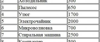
For simplicity, you can use a ready-made table that shows the ratings of standard fuses for various consumers based on their connection to a 220 V household network.
| Electrical appliance power, W (BA) | 10 | 50 | 100 | 150 | 250 | 500 | 800 | 1000 | 1200 |
| Fuse rating, A | 0,1 | 0,25 | 0,5 | 1,0 | 2,0 | 3,0 | 4,0 | 5,0 | 6,0 |
| Electrical appliance power, W (BA) | 1600 | 2000 | 2500 | 3000 | 4000 | 6000 | 8000 | 10000 |
| Fuse rating, A | 8,0 | 10,0 | 12,0 | 15,0 | 20,0 | 30,0 | 40,0 | 50,0 |
Replacing the fuse
When replacing a fuse, be sure to unplug the electrical appliance to avoid electric shock!
There is an unspoken rule: if after the second replacement the fuse blows again, look for a fault in the electrical appliance itself. This means that the electrical appliance needs to be repaired.
Never set a fuse to a higher current, such attempts will certainly lead to even greater damage to the device, even to the point of irreparability!
Be careful when purchasing a new fuse. Correctly determine the type and current rating of the replacement candidate. It is best to purchase electronic components from trusted suppliers that guarantee product quality, such as Conrad Electronic.
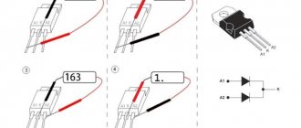
Checking the fuse, fuse fault indicator
You can check the fuse-link with any continuity tester or tester. The goal is to ensure that the fuse circuit is intact and capable of conducting electrical current.
To avoid electric shock, checking the fuse is only allowed when the electrical appliance is turned off!
In addition, you can buy or make your own fuse blown indicator, which will notify you that the fuse has blown.
The circuit diagram of such a device is extremely simple and is shown in the following figure.
LED HL1 is connected in parallel to the fuse contacts, through current-limiting resistor R1 and diode VD1, to protect against reverse voltage. Diode VD1 must be selected based on the reverse voltage exceeding the mains voltage. For a 220 V network, the reverse voltage for the VD1 diode must be at least 300 V; for example, the 1N4004 diode or the domestic KD109B meets these requirements.
The indicator does not light if the fuse is good, and lights up if it is blown.
The indicator does not light if the load is disconnected.
This circuit is very convenient to complement home-made power supplies.
By slightly changing (simplifying) the circuit, you can get a fuse blown indicator on a neon lamp, although it does not look as effective as an LED.
Fuse repair
Ordinary people think that fuses are beyond repair, but in reality this is not the case. Most types of fuses can be repaired and given a second, third, and so on. The fuse housing, as a rule, is very rarely destroyed; the wire inside burns out, and the repair consists of replacing it. The main task in this case is to use a wire similar to a fuse.
If you need to replace a fuse very quickly and do not have spare parts on hand, you can use the following method:
Remove the paint and varnish from a wire of the appropriate diameter (remove until shiny) and wind a few turns around each fuse contact, then insert the fuse into the holder. This method is popularly called “bug”. It can be used to very quickly check the health of the device, but it is unreliable and can be used as a temporary solution to the problem.
The next method is the so-called “factory” one. You'll need a soldering iron and maybe a Dremel or screwdriver to make the repair, but the fuse after the repair will look like it came straight out of the factory.
Heat the ends of the cup contacts with a soldering iron and release the holes on the ends of the solder using a toothpick or something similar. Sometimes the holes are too small or completely absent, so they need to be drilled. Use a small diameter drill of 1-2 mm.
Pass a wire of the appropriate diameter through the holes and solder it to the contacts of the cup.
The fuse is ready!
How to make a fuse with your own hands?
Primary interest in the topic arose due to the lack of commercially available 200 mA fuses, the same ones used by the manufacturer in the Mastesn multimeter. I tried setting it to 160 mA, but nothing good came of this idea - they “burn” almost after every measurement. I set it to 250 mA (no incidents so far). And since I go towards achieving my goal with a bit of passion, and besides, I’m no stranger to finding a way out of difficult situations “at random,” it’s not so rare to have to change burnt fuses. My next voyage to places selling electronic components, this time regarding 0.5 and 1 ampere fuses, was again disappointing. Fortunately, radio amateurs don’t have the habit of throwing anything away (they can only pick it up and get it in any available way), so a certain number of blown fuses have already accumulated.
Repairing a fuse, or as they used to say in the old days, “putting a bug,” as I initially imagined, is not at all a tricky matter. There are plenty of instructions on this matter on the Internet. All it takes is finding wires of suitable thickness, and the rest is a matter of technique.
Table of dependence of melting current on wire diameter
True, there was no information on where to find the necessary wires with a diameter of 3 microns (0.03 mm).
Calculation of fuse wire diameter
To repair the fuse, you need to replace the burnt wire. When manufacturing fuses in factories, calibrated silver, copper, aluminum, nickel, tin, lead and wires of other metals are used, depending on the amperage and speed.
Only red copper of calibrated diameter is available for making a fuse in your home. All electrical wires are made of copper, and the more elastic the wire, the thinner the conductors inside it and the greater their number. Therefore, all the technology proposed below is focused on the use of copper wire.
When choosing a fuse for equipment, developers are guided by a simple law. The fuse current must be higher than the maximum power consumption of the product. For example, if the maximum current consumption of the amplifier is 5 amperes, the fuse is selected at 10 amperes. The first thing you need to find on the fuse body is its marking, by which you can find out what current it is designed for. Often the current value is written on the product body, next to the location where the fuse is installed. Then use the table below to determine what diameter wire you will need.
What to do if the fuse breaks?
There is an opinion that a fusible link is an element that cannot be repaired. And the only way out if it burns out is replacement
Moreover, it is very important to choose the right new fuse while maintaining its rating, that is, the maximum permissible current - otherwise it will not be the fuse that will burn out, but the entire device. If it is not possible to determine the rating of a burnt product, then you need to choose it based on the power of the device, which is usually indicated on its body or on the label
In order to calculate the current, you can use the formula:
I nom = P max U
, Where
I nom
- fuse rating, measured in amperes (A);
Pmax
— maximum power of the device, measured in watts (W);
U
— voltage in the electrical network where the power comes from, in volts (V).
Another way to determine the required insert rating is to look at it in a special table, which indicates which standard fuse is used for a particular maximum power of the device:
- 10 W - 0.1 A
- 50 W - 0.25 A
- 100 W - 0.5 A
- 150 W - 1 A
- 250 W - 2 A
- 500 W - 3 A
- 800 W - 4 A
- 1000 W - 5 A
- 1200 W - 6 A
- 1600 W - 8 A
- 2000 W - 10 A
- 2500 W - 12 A
- 3000 W - 15 A
- 4000 W - 20 A
- 6000 W - 30 A
- 8000 W - 40 A
- 10000 W - 50 A
But in many situations it is not possible to replace the fuse with a new one. For example, when a fuse element in a car electrical system has burned out, and you are far from stores where you can buy a replacement. In this case, it is worth knowing that almost any failed fuse can be “reanimated”. Indeed, in most cases, the only thing that distinguishes a working element from a non-working element is a burnt copper wire. And it can always be replaced, without changing the technical characteristics of the product itself. The main condition is to maintain the wire diameter, then the device will work as before.
Operating principle of fuses
The operating principle of disposable protective devices is very simple. Inside each of them there is a calibrated wire connecting the contacts. If the current value does not exceed the maximum permissible standards, it heats up to approximately 70 degrees. When the electric current exceeds the specified value, the heating of the wire increases significantly. At a certain temperature it begins to melt, causing an electrical circuit to break. Wiring burnout occurs almost instantly. For this reason, fuses got their name - fuse link.
In various fuse designs, the fuse is selected in such a way that operation occurs at the set current value. During operation, fuses periodically fail and must be replaced. As a rule, they are not repaired, but many home craftsmen restore them quite successfully.
Since only the wire itself burns out, and the housing remains intact, it must be replaced, and the device will continue to perform its functions. New technical characteristics are often not only not inferior to the old device, but also in many ways superior to it, since the quality of hand assembly is always higher than the factory one. The main condition is the correct choice of conductor material and calculation of its cross-section.
APPENDIX 1 - INFORMATION OF NEW SEMICONDUCTOR (ELECTRONIC) TIME AND INTERMEDIATE RELAYS
Category: M.A.
Shabad “Relay protection of transformers” The main technical characteristics of new serial current, time and intermediate relays, which are used in modern relay protection devices for various elements of electrical installations, including 10 kV transformers, are given on the basis of data from the manufacturer - the Cheboksary Electrical Hardware Plant.
Maximum current relays of the RST-11 and RST-13 series. Instantaneous current relays of these series, in their purpose, are electronic analogues of electromechanical relays of the RT-40 series, the description of which is given in [11|.
The principle of operation of the RST-11, RST-13 relays is based on measuring the time interval during which the instantaneous value of the measured current exceeds a certain reference value. Accurate operation of these relays is therefore ensured for any possible distortion of the current sinusoid at the relay input, even if the current error of the current transformers is 80-90% [14]. As can be seen from the dependence A =ψ(f) in Fig. 28, and, the values of the current error of current transformers practically do not exceed 80% and, thus, relays of the RST-11, RST-13 series can reliably operate at such short-circuit current ratios at which the RT-40 series relays fail due to their vibration contact system.
Causes of blown fuses
Let's start with the most important thing - the causes of blown fuses. After all, nothing happens and before inserting the “bug”, it is necessary to determine the reasons for the fuse failure.
There may be several of them:
Fuse links. How to choose and calculate current. Operation and Application
Fuses: Electrical components to protect equipment from short circuits and overvoltage by cutting off power when current load limits are exceeded. The circuit is opened by melting a safety wire of a certain thickness. Several types of these devices are known to the industry. They all differ in internal and external design features and operate on the same principle.
Nowadays, more practical reusable circuit breakers are used to protect electrical equipment in the apartment, but disposable fuse links are still found in traffic jams. They are especially relevant for premises of temporary and old buildings, where the installation of effective modern panels is not economically justified. In household appliances there is still no alternative to the classic fuse.
Fuse links are also widely used in industry. The productivity of an entire plant or utility network may depend on them. It is better not to buy industrial fuses secondhand, from the market or from unverified organizations. A wise decision is to turn to electronics professionals, for example, in the online store Conrad.ru. In such matters, the miser pays not twice, but three times
Description of the operating principle of a fuse link (fuse)
The principle of operation of the fuse is extremely simple. When a rated current flows through the wire connecting the fuse contacts, this wire heats up to a temperature of about 70 °C. But when the current is exceeded, the wire heats up more, and when the melting temperature is exceeded, it melts, i.e. burns out. It is for this reason that fuses are also called fuses or fusible links. The higher the current, the faster the heating, the faster the melting occurs, and, accordingly, the fuse blows.
Thus, all fuse links operate on the same principle - excess current in the circuit causes overheating and melting of the wire inside the fuse and, as a result, disconnection of this circuit from the power source.
There are two main reasons for the burnout of fuse links: surges in the supply voltage and a malfunction within the electrical appliance itself.
We choose the diameter of the fuse wire - we analyze all the subtleties of the issue
A homemade copper wire fuse can be a great temporary way to replace a blown fuse. But if you decide to do this, it is extremely important to choose the correct cross-section of the conductor itself that you will use. Why this is important, what causes fuses to blow and how to temporarily eliminate this deficiency, we will look at in our article.
General concepts, introduction to tubular fuses
The most common fuses are the so-called tubular ones. They are a ceramic or glass tube with metal cup contacts at the ends. These cups are connected to each other by wire, the cross-section of which, as already mentioned, determines the rated current of the fuse. This current is indicated on the tube or one of the contact parts of the fuse. For example: F0.5A - this means that this fuse is rated for a current of 0.5 amperes.
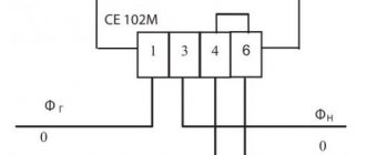
On electrical circuit diagrams, a fuse is indicated by a rectangle with a straight line passing through it. Next to the conventional graphic designation its position designation is indicated, for example F1 (F – fuse, fuse in English); and if this does not clutter the circuit - the rated current, for example 100 mA.
How to determine the fuse rating from the case and on the board
Before you change something that went wrong, you need to understand what went wrong. In our case, it burned out. We can only rely on the inscription on the board itself or on the fuse, because other ways to find out what kind of fuse it is are very unstable and unreasonable. After all, a working fuse will show nothing more than zero resistance, but a bad open circuit. At the same time, do not take it to a laboratory for analysis to find out what kind of material it was. Let's look at examples of fuse designations on the board and SMD elements. By the way, sometimes you can use a resistor instead of a fuse.
Fuse ratings are approximate
The fuse rating on the microwave is about 12 A (2 kW). The fuse rating in the computer power supply is 400 W - 2.5 A, 600 W-4, 800 W - 5 A.
In general, you can roughly calculate the fuse based on the power of the consumed device. That is, we divide the power by the voltage and get the current. It is this current with a small margin that will become the rating of our fuse. You must understand that even a fuse for protection has a small power reserve of about 10 percent. This is due to inrush induction currents passing through the inductance and when charging large capacitors.
Calculation of conductors for fuses
where: d – core diameter, mm; k – material-dependent core coefficient according to the table.
where: m is a coefficient depending on the conductor material according to the table.
Formula (1) is used for low currents (thin conductors d = (0.02–0.2) mm) and formula (2) for high currents (thick conductors). Odds table.
The conductor diameter for use in a fuse is calculated using the formulas: For low currents (thin conductors with a diameter of 0.02 to 0.2 mm):
For high currents (thick conductors):
The amount of heat generated by the fuse is calculated by the formula:
where: I – current flowing through the conductor; R – conductor resistance; t – time elapsed before the fuse trips under the influence of current I.
The fuse resistance is calculated using the formula:
where: p – resistivity of the conductor material; l – core length; s is the cross-sectional area of the conductor.
To simplify calculations, the resistance is assumed to be constant. The increase in fuse resistance due to increased temperature is not taken into account.
Knowing the amount of heat required to melt the fuse, the melting time can be calculated using the formula:
where: W – amount of heat required to melt the fuse; I – thermonuclear current; R – fuse resistance.
5.4. Checking cables for thermal stability during short circuits
As a rule, this check is performed only for cables connected to the main (or input) distribution board.
In case of short circuits, the heating temperature of the conductor should not exceed the maximum permissible temperature for conductor insulation.
The cross section of the conductor corresponding to this condition is determined by the formula
The values of coefficients K2, calculated in accordance with the temperatures max and initial specified in PUE3, are given in table. 5.14.
The selected section must satisfy the condition Sd.n. >= Skd,
where Sd.n. is the cross-section of the conductor corresponding to the long-term permissible current.
Table 5.14 K2 coefficient for copper and aluminum conductors
K2 coefficient for copper and aluminum conductors
| Insulation conductor | Temperature, C | K2 for conductor | Note | ||
| Initial | T final at short circuit | copper | aluminum | ||
| Rubber | 65 | 150 | 2 | 1,98 | According to the PUE |
| 60 | 160 | 1,85 | 1,83 | According to foreign companies | |
| PVC | 65 | 150 | 2 | 1,98 | |
| 70 | 160 | 1,97 | 1,95 | ||
| Polyethylene | 65 | 120 | 2,44 | 2,23 | |
| 70 | 120 | 2,56 | 2,54 | ||
| Vulcanized cross-linked polyethylene | 90 | 250 | 1,8 | 1,57 | |
| — | — | — | — | ||
| Paper insulation | 80 | 200 | 1,76 | 1,74 | |
| 80 | 160 | 2,1 | 2,08 | ||
What do copper wire fuses look like and do?
In appearance, the fuse is a glass or ceramic flask, inside of which a calibrated copper wire is stretched. It is connected to the contacts of elements located in metal plugs by welding or spot welding. The diameter of the wire depends on the current strength for which the fuse is designed. The flask (tube) of a product with a high rated current is sometimes filled with quartz sand. In appearance, such fuses are called tubular.
Another common type of this device is automotive knife guards. Depending on the current rating, they are painted in different colors:
- 5 A – orange;
- 7.5 A – brown;
- 10 A – red;
- 15 A – blue;
- 20 A – yellow;
- 25 A – colorless (transparent);
- 30 A – green;
- 40 A – purple;
- 60 A – blue;
- 70 A – black.
The principle of operation of the insert is extremely simple. The fuse lights up and electric current begins to flow through the wire. This heats the wire. As long as the current does not exceed the value set in the fuse, the wire temperature remains at about 70 degrees Celsius. As soon as the current values exceed the permissible limits, the heating of the wire increases to the melting temperature of copper, it loses its integrity, thereby breaking the electrical circuit. All this happens very quickly, almost in a split second. It is because of this principle of operation that fuses with copper wire are called fuses.
There are several types and types of such inserts. But, nevertheless, they all act the same way: the copper wire included in its composition melts and the current stops.
It is very important to understand that the fuse “trips” precisely when the permissible current value is exceeded, but the voltage in the network does not matter. In other words, the same element can be installed in a 12 V charger, in a single-phase network and in a three-phase network.
Of course, the question may arise: we are talking about the fact that the device protects against power surges in the network and immediately declares that the voltage is not important for this, how is this possible? In fact, here it is enough to recall the school physics course, or Ohm’s law, which states that the current in a section of a circuit is directly proportional to the voltage and inversely proportional to the resistance. In other words, the higher the voltage, the higher the current, since the resistance of the conductor (copper wire of a certain diameter) still remains the same.
The insert can burn out not only due to voltage surges in the network, that is, due to exceeding the rated current, but also due to a malfunction within the device itself in which it is installed. You can determine for yourself the reason for the failure of the insert: if after replacing it twice the element burns out again, the device itself is faulty. Sometimes a situation arises when the reason for the failure of an insert is its poor quality, but this is rare.
Selecting fuses to protect power transformers
The main conditions for choosing fuses for power transformers are the following parameters. The rated voltage of the fuses and their fuse links must be equal to the rated mains voltage:
Fuses in the USSR were produced at rated voltages corresponding to GOST 721-77, including 6; 10; 20; 35; 110 kV. The rated voltage is indicated in the name of the fuse, for example PK-6, PK-10, PSN-10, PSN-35, etc.
Installing a fuse intended for a lower voltage network, i.e. creating the condition Unom pr < Unom. c is not allowed to avoid short circuit. due to the fuse insulation being blocked. At the same time, it is not allowed, without special instructions from the manufacturer, to use a fuse in networks with a lower rated voltage due to the risk of overvoltages when disconnecting the short circuit. The rated breaking current of the selected fuse must be equal to or greater than the maximum short-circuit current. at the fuse installation location:
As applied to power transformers, current/k. max is calculated for a three-phase short circuit. at the high voltage terminals of the transformer, i.e. where the fuses are installed. In this case, the mode of the supply system is assumed to be maximum, which corresponds to the lowest resistance of the supply system to the point of connection of the transformer in question. The recharge of the short circuit area should also be taken into account. electric motors connected in the same section as the transformer in question. Rated shutdown currents are indicated in GOST and factory information.
Fuses with voltages over 1000 V are available with a rated shutdown current from 2.5 to 40 kA (GOST 2213-70). (The previous name for the rated breaking current was the maximum breaking current.)
Selection of 10 kV fuses for transformer protection
- By rated voltage: i.e. the rated voltage of the fuse Unom.pr must correspond to the rated network voltage: Unom = Unom.s
- According to the rated shutdown current: Iо.nom >= Iк.max i.e. the rated shutdown current of the fuse according to its rating data must be greater than or equal to the maximum value of the short-circuit current. at the location where the fuse is installed. When calculating short-circuit currents. it is necessary to take into account the recharge of the short circuit area. electric motors.
- According to rated current. The rated current of the fuse is equal to the rated current of the element being replaced. A replaceable fuse element with a fine-grained filler, for example a PC type, is considered to be a cartridge (one or more) with quartz sand, a fusible element, an operation indicator or an impact device, assembled in a factory.
The rated current of the fuses protecting power transformers on the 10 and 0.4 kV sides is selected from the table
Recommended values of rated currents of fuse links 1nom fuses for three-phase power transformers 6/0.4 and 10/0.4 kV
| Rated current, A | ||||||
| Transformer power, kV* A | transformer on the side | fuse link on side | ||||
| 0.4 kV | 6 kV | 10 kV | 0.4 kV | 6 kV | 10 kV | |
| 25 | 36 | 2,40 | 1,44 | 40 | 8 | 5 |
| 40 | 58 | 3,83 | 2,30 | 60 | 10 | 8 |
| 63 | 91 | 6,05 | 3,64 | 100 | 16 | 10 |
| 100 | 145 | 9,60 | 5,80 | 150 | 20 | 16 |
| 160 | 231 | 15,4 | 9,25 | 250 | 32 | 20 |
| 250 | 360 | 24,0 | 14,40 | 400 | 50 | 40 |
| 400 | 580 | 38,3 | 23,10 | 600 | 80 | 50 |
| 630 | 910 | 60,5 | 36,4 | 1000 | 160 | 80 |
Note It is assumed that fuses of the PN-2 type are used on the 0.4 kV side, type PK-6 on the 6 kV side, and type PK-10 on the 10 kV side.
Fuses for protecting the voltage transformer on the HV side
Voltage transformers of 110 kV and above are protected only on the low voltage side by automatic circuit breakers or fuses. For voltage transformers of 6, 10 and 35 kV, current calculation for the fuse link is not carried out.
The fuse for protecting the voltage transformer on the HV side is selected only according to the voltage class. For each voltage class, special fuses of the PKN (PN) type are produced - 6, 10, 35 (depending on the voltage class); they are used exclusively to protect voltage transformers.
Disadvantages of fuse-based transformer protection
Protection with fuses is structurally the simplest, but has disadvantages - instability of protection parameters, which can lead to an unacceptable increase in the protection response time for certain types of internal damage to power transformers. When protecting with fuses, difficulties arise in coordinating the protection of adjacent sections of the network.
Read also:
- Main types of relay protection of transformers
- Gas protection of power transformer
- Operating principle of transformer differential protection