Operating modes of electrical circuits
An electrical circuit, depending on the value of the load resistance R, can operate in various characteristic modes:
· nominal
· agreed upon;
· idle move;
· short circuit.
The nominal mode is the design mode in which the circuit elements (sources, receivers, power lines) operate under conditions corresponding to the design data and parameters.
The insulation of the source, power line, and receivers is designed for a certain voltage, called the rated voltage. Exceeding this voltage leads to insulation breakdown, increased current in the circuit and other emergency consequences.
The thermal regime of energy sources or receivers is designed to release a certain amount of heat in them, that is, for a certain power, and the latter depends on the square of the current RI2, rI2.
The thermal current calculated is called the rated current.
The rated power value for an electrical energy source is the maximum power that the source, under normal operating conditions, can deliver to an external circuit without the danger of insulation breakdown and exceeding the permissible heating temperature.
For electrical energy receivers such as motors, this is the power that can be developed at the shaft under normal operating conditions. For other receivers of electrical energy (heating and lighting devices) this is their power at nominal mode. Rated values of voltages, currents and powers are indicated in product data sheets.
Matched mode of operation is the mode in which the electrical circuit (source and receiver) operates when the load resistance R is equal to the internal resistance of the source r. This mode is characterized by the transfer of the maximum possible power from a given source to the receiver. However, in a coordinated mode, the E.P.D. h = 0.5 is low and for high-power circuits operation in a coordinated mode is not economically profitable. Matched mode is used mainly in low-power circuits if the efficiency. is not significant, but it is necessary to obtain as much power as possible in the receiver.
No-load and short circuit mode. These modes are the limiting modes of operation of the electrical circuit.
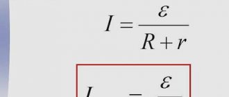
In idle mode, the external circuit is open and the current is zero. Since the current is zero, the voltage drop across the internal resistance of the source is also zero (rI = 0) and the voltage at the source terminals is equal to the emf (e = U). From these relationships follows the method of measuring the EMF (2.7) of the source: with the external circuit open, a voltmeter whose resistance can be considered infinitely large is used to measure the voltage at its terminals.
In short circuit mode, the source terminals are connected to each other, for example, the load resistance is closed by a conductor with zero resistance. The voltage at the receiver is zero.
The resistance of the entire circuit is equal to the internal resistance of the source, and the short circuit current in the circuit is equal to:
Ik.z. = e/r.
(2.14)
It reaches the maximum possible value for a given source and can cause overheating of the source and even damage it. To protect sources of electrical energy and supply circuits from short circuit currents, fuses are installed in low-power circuits, circuit breakers are installed in more powerful circuits, and special high-voltage circuit breakers are installed in high-voltage circuits.
It is known that an electrical circuit is a collection of certain devices that provide a constant, continuous passage of electric current. The circuit cannot operate if any elements are missing; Both sources of energy and its conductors must be present, and receivers, as a rule, are the main devices that form this circuit. If we consider that in an electrical circuit there are various elements that are divided into three main groups: energy sources, current conductors and receivers, i.e., those elements that are powered by current and convert energy into its other types, then we can assume that there are different modes of operation of electrical circuits. Basic operating modes of electrical circuits As mentioned earlier, any electrical circuit can have a rather complex structure, depending on the number of elements in it and its branching. All this leads to the fact that the circuit can operate in different modes. There are three main operating modes: load (or matched), short circuit mode, and idle mode. They differ from each other in the load on the electrical circuit. You can also select the nominal operating mode. In this mode of operation, all devices in the circuit operate under the conditions specified for them as optimal. These characteristics are prescribed by the manufacturer in the passport data when the device is manufactured at the factory. Load, or coordinated operating mode . If any receiver is connected to an energy source in an electrical circuit, then it has a certain resistance. Such a receiver can be any device, for example a light bulb. If there is voltage, then Ohm's law , thus, the emf of the source is obtained from the sum of the voltages of the external section of the circuit and the internal resistance of the source. The voltage drop in the external circuit will be equal to the voltage at the source terminals. It depends on the load current: the lower the load resistance, the higher the current and, accordingly, the lower the voltage at the terminals of the circuit’s power source. In other words, we can say that the load or coordinated operating mode is a mode in which a high-power load is transferred from a source. In this mode, the load resistance is equal to the internal resistance of the source, and maximum power is consumed. However, this mode is not recommended, since if the nominal values are exceeded for a long time, the devices may fail. Idle mode . This mode of operation of the electrical circuit characterizes its open state - there is no current, and all elements are disconnected from the power source. In this state of the circuit, the internal voltage drop is zero, and the voltage at the terminals of the power source coincides with the emf of the source. That is, we can say that the idle mode characterizes the electrical circuit when it is in an open state and the load resistance is completely absent or disconnected. This state of the circuit can be used to measure the EMF of the power source. Short circuit mode . This operating mode is considered an emergency; the electrical circuit cannot operate normally. A short circuit occurs when two different points in a circuit are connected, the potential difference of which is different. This condition is not intended by the device manufacturer and interferes with its normal operation. In this operating mode, the terminals of the energy source are closed by a conductor (“shorted”), and its resistance is close to zero. Often, a short circuit occurs in cases where two wires are connected that connect the source and receiver in the circuit; as a rule, their resistance is negligible, so it can be called zero. When a short circuit occurs, the current in the circuit significantly exceeds the rated values (due to the lack of resistance). This can render the power source and receivers in the electrical circuit unusable. In some cases, this is the result of improper actions on the part of personnel working with electrical equipment.
Operating modes of a linear electrical circuit: short circuit (short circuit) and idle (idle)
Page 1 of 5Next ⇒
Introduction
The material presented in the methodological manual under consideration is devoted to the analytical analysis of a linear electrical circuit operating on a continuously changing linear load.
This manual discusses: the boundary modes of a given circuit, as well as the matching mode, and their energy parameters. A special place in this manual is given to the consideration of a fire hazardous mode - a short circuit mode.
An analysis of the boundary modes of the original linear electrical circuit, performed using the appropriate mathematical apparatus, allows us to substantiate the “existence” of idealized sources: an EMF source, a current source.
Idealized sources have found wide application in the course of the discipline "Electronics" and serve as the basis for carrying out calculations of electronic circuits using application software packages for personal computers - personal computers (PCs).
This manual shows the relationship between the methods of higher mathematics and physics used in the analytical analysis of a linear electrical circuit, and on this basis, reasonable patterns are obtained: energy modes of functioning of a linear electrical circuit.
The team of authors, presenting the material presented in this manual, proceeded from the fact that the reader has a full command of the mathematical apparatus in the scope of the first course of “Higher Mathematics” and has creatively mastered the following sections of the course of general physics: “Mechanics. Electricity and magnetism."
In this manual, using the methods of mathematical analysis, we study the function that arises in the process of studying a linear electrical circuit. A detailed study of this function has been performed for the first time. This study, carried out by A.G. Stepanov, allows us to substantiate an engineering-physical approach aimed at achieving the maximum value of the circuit efficiency: in practical terms, quite close to its maximum value. The same study allows us to outline a further path of theoretical research in order to substantiate the existence of the criterion necessary for engineering modeling of the idle mode, without using the “break” mode of the branch containing the passive receiver of electrical energy.
Creative mastery by listeners, masters, cadets, students of the discipline “Electrical Engineering and Electronics” will allow them to successfully study a number of disciplines of a special profile in the further educational process.
Special thanks to A. G. Stepanov, Doctor of Technical Sciences, Professor
S.V. Puzach - Head of the Department of Engineering Thermal Physics and Hydraulics, Colonel of the Internal Service of the State Guard Service of the Ministry of Emergency Situations of Russia, for constructive scientific recommendations and creative cooperation.
Operating modes of a linear electrical circuit consisting of a real source of electromotive force EMF and
Time-varying linear load.
Energy characteristics of circuit modes
Operating modes of a linear electrical circuit: short circuit (short circuit) and idle (idle)
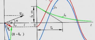
Consider the following linear circuit, the diagram of which is shown in Fig. 1.
Rice. 1. Linear electrical circuit diagram:
E
— electromotive force (EMF), [V];
r
0 – internal resistance of the EMF source, [Ohm];
— load resistance, [Ohm]; (1), (2), (3) – positions of the variable resistor motor.
Let's write down the initial data for this linear electrical circuit:
Let us assume that at the initial moment of time the motor (3) of the variable load resistor is in an average state between two limit states (1) and (2).
Each of the possible states characterizes a certain operating mode of the entire circuit, determined by the value of the load resistor with resistance .
It is necessary to determine each of the possible circuit modes and their corresponding energy characteristics (parameters).
Several additional clarifications should be made regarding the boundary modes of operation of the analyzed circuit.
If the engine is in state (1), then this actually corresponds to the exclusion of the load, i.e. short-circuiting it. Hence, the name of the mode is “short circuit” (SC).
If the engine is in state (2), then with a large load resistance, this emits another possible boundary mode - “idle speed” (XX).
If a variable resistor, as an element of an electrical circuit, is used to change the amount of current flowing in a given branch, then the variable resistor is said to be turned on like a rheostat.
If a variable resistor is designed to change the magnitude of the potential difference between a given point in an electrical circuit and a point whose potential is zero, then the variable resistor is considered to be connected as a potentiometer.
It is necessary to make an addition: at some point in the electrical circuit its potential is either actually equal to zero, i.e., this point is “grounded”, or its potential is conditionally assumed to be zero.
If the variable resistor motor is in state (3) - the average value of the variable resistor, then according to Ohm’s law, we can write the following expression for the current flowing in the circuit in question:
The choice of the structure of the analyzed circuit, presented in Figure, can be explained as follows.
The composition of modern technical systems, as a rule, includes in the form of elements of these systems, for example, wired communication lines, computer networks, which are built without the use of fiber-optic communication lines (FOCL). Due to the influence of a number of special factors on these elements of systems: such as, for example, electromagnetic forces created by thunderstorm activity, a temperature front that occurs during a fire, and a number of other factors, a change in the insulation resistance values of these elements is noted.
Therefore, the amount of current flowing through these elements, in some cases, depends not only on the size of the electrical energy receiver, but also on the value of their insulation resistance. In this case, the value of insulation resistance in each specific case is capable of deviating from its nominal value, due to special factors, in general, according to a nonlinear law. The linear law of change in the value of insulation resistance is observed only as a special case, with a sufficient number of additional restrictions introduced, and therefore it should be considered only as the very first approximation when studying this phenomenon.
In the analytical study of a linear electrical circuit carried out below, it is assumed that the value of the insulation resistance of the transmission line is taken into account in the value of the consumer (receiver) of electrical energy.
In fact, the change in the insulation resistance value of the consumer (receiver) should probably occur according to a linear law, if the following restrictions are initially introduced: constancy of the ambient temperature, constancy of its pressure, constancy of its humidity, absence of mechanical deformation of the insulation, and in addition absence of influence of special factors.
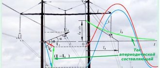
For each of the above modes of a linear electrical circuit, we will determine the energy parameters (characteristics) of the circuit and construct graphs corresponding to these parameters.
Short circuit mode
Short circuit mode
(
short circuit) of an electrical circuit is a mode in which the value of the load resistance tends to zero, and the value of the current flowing through the load tends to the maximum possible value.
The above definition essentially contains a necessary and sufficient condition that characterizes the short circuit mode. In our further presentation of the material, in some mathematical relationships, the abbreviation , will be written above the equal sign, indicating that this relationship is written by definition.
Based on the definition of the short circuit mode, and using relation (1), we obtain an analytical expression for the current in the circuit for the mode under consideration:
Before obtaining analytical expressions for various powers in the circuit under consideration, taking into account the short circuit mode, we will indicate how the power of the source of electrical energy is determined - the source of emf in a linear electrical circuit.
The power of the electromotive force source is defined as the product of the magnitude of the EMF source by the magnitude of the current flowing through this source.
Let's write down the expression for power PE
EMF source, taking into account the definition given above, in relation to the short circuit (SC) mode:
,
where the graphic symbol means that the conventionally selected positive direction of the current in the circuit under consideration, coinciding with the direction of the short-circuit current, is co-directed by the source emf.
By substituting expression (1.1.1) into expression (1.1.2), we obtain a relation for the power of the source in short-circuit mode and taking into account the parameters of the circuit under study (analyzed):
From the obtained relationship (1.1.3) it follows that in the short-circuit mode the value of the power of the EMF source is determined according to the quadratic law.
In the following presentation, expression (1.1.3) will be used to plot the dependence of the power of the EMF source on the changing value of the load resistor (Fig. 3).
Let's find an analytical expression for P
0 short circuit
-
power loss on the internal (
r
0) resistance of the EMF source in short circuit mode
.
For this purpose, it is advisable to use the Joule–Lenz law for the regime under consideration. The expression of the Joule–Lenz law for this case takes the following form:
Substituting into relation (1.1.4) the expression for short-circuit current taken from relation (1.1.1), we find:
The resulting expression (1.1.5) indicates that the value of power loss, which represents the rate of conversion of electrical energy into thermal energy, and released at the internal resistance of the EMF source in short-circuit mode, also obeys the quadratic law.
The next point of our research is to determine the analytical expression for the power released at the load resistance ( P
nKZ) in the considered mode, and finding its value.
The analytical expression of the Joule–Lenz law for this mode has the following form:
.
Taking into account the definition of the short circuit mode, and taking into account relation (1.1.1), from relation (1.1.6) we find:
.
From expression (1.1.7) it follows that the value of power loss on a resistive element with resistance in short-circuit mode is zero. Note that this result can also be obtained purely qualitatively, using for this purpose only the definition of the short circuit mode.
Let us determine the most important energy parameter of the circuit in short-circuit mode - efficiency factor (efficiency).
Let us recall the ratio that determines the efficiency, taken from the “Mechanics” course:
In one fundamental section of linear electrical circuits, namely the section devoted to “Electrostatics”, the most important physical concept - the concept of work, is associated with the energy characteristic of the electrostatic field - potential, the following relation:
.
From relation (1.1.9), we find
.
Having completed the term-by-term division of the left and right sides of relation (1.1.10) by time ( t
), different from zero, we find the most general expression for power:
.
In classical mechanics, there are two analytical expressions for the concept of power:
a) in one of these expressions, power is interpreted as a physical quantity, which is determined by the value of the constancy of work performed per unit of time:
;
b) in another of these expressions, power is interpreted as a physical quantity that characterizes the speed of work performed in time:
.
It should be noted that in direct current electrical circuits only relation (1.1.12) is used, while in alternating current circuits, in general, both of these relations are used, and relation (1.1.3) is used only in sinusoidal alternating current circuits current, which are a special case.
If we apply relations (1.1.11, 1.1.12) to a DC circuit, then we can analytically express the power through work:
Using the basic notation for DC:
and expression , we find an analytical expression for power containing the most important parameters of the DC circuit:
Using the expression of Ohm's law written for the passive section of the circuit, we find:
Substituting relation (1.1.17) into relation (1.1.16), we obtain an analytical expression for the Joule-Lenz law:
The relationships given above made it possible to derive the Joule–Lenz law, based on the integral form of writing the following physical concepts: power, current and the application of Ohm’s law for a section of the circuit.
The use of expression (1.1.18) allows us to write in general form the mathematical relationship for the coefficient of efficiency (efficiency) in short-circuit mode:
.
Based on the relationship, it is possible to carry out a physical interpretation of the concept of efficiency for the linear electrical circuit under consideration, regardless of its operating mode.
The efficiency factor in the linear electrical circuit under consideration should be understood as the ratio of the amount of power released at the load to the power developed by the energy source.
Considering that the magnitude of the short circuit current and the magnitude of the EMF source are different from zero, and sequentially performing the procedure of dividing the numerator and denominator of expression (1.1.19) by these values, we will find another relationship for the efficiency of this mode, expressing it through the initial parameters the chain itself:
Having carried out the procedure for passing to the limit in relation (1.1.20), we find the efficiency value for the short-circuit mode:
Conclusion:
Short circuit mode is critically dangerous : in this mode, all the power supplied by the source to the circuit is released into the internal ohmic resistance of the source itself.
In such an emergency situation, electrical energy is converted into thermal energy solely through the internal resistance of the energy source. Physically, this phenomenon characterizes the destruction of an energy source and is the main cause of a fire hazard.
It should be noted that there are already devices developed and implemented in engineering practice that largely manage to respond to the thermal effect of increasing current in the circuit.
These devices and their design features, and the most important parameters will be discussed in detail in the course “Fire safety of electrical installations.”
Idle mode
The idle mode (idle mode) of an electrical circuit is such a mode of operation in which the value of the load resistance tends to infinity, and the value of the current flowing through the load tends to zero.
The above definition essentially contains necessary and sufficient conditions that characterize the idle mode.
Using the definition of idle mode, and applying Ohm's law for the complete circuit (1), we will write an analytical expression for the current in the analyzed mode:
Drawing an analogy with the previously considered short circuit mode, we can write an analytical expression for the power of the EMF source in idle mode:
The use of this technique allows us to create an analytical expression for the power released by the load in the mode under consideration:
The analytical expression for power losses—the power released at the internal resistance of the EMF source—has the form:
.
Applying relations (1.2.2) and (1.2.3), we find the value of the power of the EMF source in idle mode:
.
The physical content of the obtained value of relation (1.2.5) is as follows: if in the XX mode the value of the load resistance is infinitely large, which corresponds to an open (broken) branch containing the load, then the current in the circuit under consideration is zero, and therefore the power is also zero , generated by a source of electromotive force.
Let us determine the value of the power loss on the internal resistance of the EMF source itself:
.
Application of the Joule-Lenz law allows us to write down an analytical expression for the power released by the load in idle mode :
.
To analyze relation (1.2.7), it is advisable to use the following theorems, known to the reader from the course of differential calculus, these theorems: on finding the limit of a product, calculating the limit of a fraction, finding the limit of a degree:
.
So, in relation (1.2.8) we obtain an uncertainty of the following form: 0·∞.
Let us reveal this uncertainty in two ways. The first way to reveal uncertainty of the form 0·∞ is mathematical. From the course of mathematical analysis it is known that the uncertainty of the specified type is revealed using the method of reducing this uncertainty to the following types of uncertainties: .
In other words, it is necessary to reduce the uncertainty we obtained in relation (1.2.8) to one of the indicated types of uncertainties:
.
The resulting relationship (1.2.9) represents the uncertainty of the type we require, namely the form: .
The resulting uncertainty can also be revealed using the following two methods.
Both of these methods belong to mathematical methods. The first method is the method of disclosing species uncertainty: using the Johann Bernoulli–L'Hopital rule.
Let us briefly recall the mathematical essence of the Johann Bernoulli-L'Hopital rule. When determining the limit of a continuous function, often, as a result of substituting the limit value of the argument of this function, one arrives at the following types of uncertainties:
.
Finding the limit of a function in such cases is called uncertainty discovery. The theorem given below, historically known as L'Hopital's rule, is a mathematical basis that allows us to reveal the first two uncertainties mentioned above, that is, uncertainties of the form: . In fairness, it should be noted that the Marquis de L'Hopital was the only student of the outstanding Swiss mathematician Johann Bernoulli. It was thanks to Johann Bernoulli that the Marquis de L'Hopital received systematic information about the then new direction in mathematics - the analysis of infinitesimals.
Subsequently, from this teaching arose a harmonious, logical, harmonious direction of mathematics, called mathematical analysis. Mathematical analysis combines two areas: differential and integral calculus.
It should be noted that the Marquis de L'Hopital carefully took notes on the lectures and subsequently published them as a separate book, in the form of the first textbook on differential calculus in Europe: this historical event occurred in 1696, when the Marquis L'Hopital published in Paris under his own name the first ever textbook under Title: "Infinitesimal Analysis for the Study of Curved Lines" (in French), this book was based on the first part of Johann Bernoulli's outline.
It was precisely because L'Hopital was a student of Johann Bernoulli that historians of mathematics began to call L'Hopital's rule the Bernoulli-L'Hopital rule. Below is the formulation of the theorem, which illustrates the Bernoulli-L'Hopital rule.
Theorem.
If there are two functions such that the following conditions are satisfied for them:
that is, when both functions under consideration are continuous and differentiable,
then the limiting values of these functions are respectively equal to:
,
and the relations of these functions have the following form:
then the indicated uncertainties can be revealed using the Bernoulli-L'Hopital rule:
The theorem we presented above remains in force even if its condition is replaced by the condition:
i.e., the theorem can be applied to the disclosure of uncertainties of the form .
In all conditions of this theorem, the limit can be understood as one-sided. This theorem is also valid for one-sided limits and in the case when the limit value of the variant, i.e., also denotes infinity.
Let us apply the Bernoulli-L'Hopital rule to the expression taken from the previously obtained relation (1.2.7), and as a result we find:
In the written relation, the corresponding functions are
are equal:
Having carried out the procedure for differentiating each of the specified functions,
we get:
Then, applying the I. Bernoulli-L'Hopital rule to the relation will reveal the above uncertainty:
Let us present another mathematical method that allows us to reveal uncertainties of the form.
In the relation, before passing to the limit, we carry out identical transformations on the expression under the limit sign. Using the abbreviated multiplication formula for the square of the sum
two numbers, we get:
Then, the expression under the limit sign will have the following
view:
Before passing to the limit, we perform the procedure of dividing the expression under the limit symbol into the ratio by the highest power option R2н, after which we obtain:
Comparing the result of the expression with the result of the expression, we come to the conclusion that they are equal to each other.
We will also indicate another method for disclosing the resulting uncertainty.
This physical method is based on the application of Kirchhoff's second law, which directly follows from the law of conservation of energy.
By applying Kirchhoff's second law, we have:
Multiplying the left and right sides of relation (1.28) by the value of the no-load current, we obtain:
Taking into account the previously obtained relations (1.2.3) and (1.2.4), due to which:
we can rewrite relation (1.29) in an equivalent form:
Using the recorded relationship, we will find, following the physical approach, the amount of load power in the idle mode.
From relation (1.2.10), we find the power in the load for the XX mode:
.
All three methods applied to uncover species uncertainty produced the same result.
Let's determine the efficiency for the idle mode (idle).
By analogy with relation (1.1.20), we write the expression defining:
.
The resulting relationship, from a mathematical point of view, represents the doubled uncertainty that arose as a result of the transition to the limit, i.e., when finding the limit from the analytical expression that determines the efficiency for the idle mode, which can be written mathematically compactly as follows.
In the numerator of the last relation, double uncertainty arose due to the fact that when the value of the resistive element, which represents a linear load, increases infinitely, i.e., when , then at the same time the magnitude of the current in the circuit decreases infinitely, i.e., expression .
You can reveal double uncertainty using identical transformations performed on the expression under the limit symbol.
.
Having passed to the limit in the resulting expression, we find the efficiency value for the mode under consideration:
Let us determine the geometric nature of the dependence in order to further construct the corresponding graph. To do this, we perform the procedure of dividing by a “corner” the following expression:
Having carried out the procedure for passing to the limit in the last relation (1.2.14), we find the numerical value of the efficiency of the circuit operating in the XX mode:
Conclusions on idle mode (idle):
1) in the XX mode, the linear electrical circuit we are considering
has a maximum efficiency value numerically equal to unity;
2) the analytically geometric nature of the dependence obeys the hyperbolic law ( Fig. 3);
General conclusion for the two previously considered short circuit and full cycle modes.
The considered linear electrical circuit, both in short-circuit mode and in XX mode, has the same values for load power.
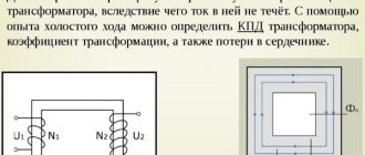
The idle mode is discussed in this lecture, taking into account the fact that this mode was widely used in the Electrical Engineering and Electronics course.
This mode was used both when considering the experience of testing a transformer, and when studying the frequency characteristics of reactive elements that are part of a series oscillating circuit, on the one hand, and when studying the amplitude-frequency and phase-frequency characteristics of the circuit, on the other hand.
1Next ⇒
Recommended pages:
Use the site search:
There are three modes of circuit operation:
- short circuit
- load mode (agreed)
- idle mode.
The main difference between these modes is the level of load on the electrical circuit. It is worth noting that the electrical circuit has another operating mode, called nominal. In this mode, all circuit elements operate under optimal conditions. These conditions are indicated in the passport data by the manufacturer.
Coordinated (load) operating mode
Any receiver connected to a source of electricity in a circuit has a certain resistance. A good example of such a receiver would be an electric light bulb. When voltage is present, Ohm's law comes into play. In this case, the electromotive force of the current source is the sum of the voltage on the external sections of the circuit and the internal resistance of the source. When the external circuit voltage drops, it affects the voltage change at the source terminals. And the voltage drop itself depends on the resistance and current. In other words, the coordinated (load) mode of operation of an electrical circuit is a load transfer process in which the power exceeds the nominal values. But using this mode is irrational, because if the values set by the factory are exceeded for a long time, the devices can simply become unusable.
Idle mode
In this operating mode, the electrical circuit is in an open state. Simply put, there is no electrical current in the circuit, therefore, each element of the circuit is not connected to a source of current. In this position, the voltage drop in the internal circuit is zero, and the source emf is equal to the voltage at the power source terminals. In other words, during idling mode, there is no load resistance in a circuit not connected to electric current.
Short circuit mode
This is the operating mode that can safely be called emergency, because... ensuring normal operation of the circuit in this mode becomes impossible, because the short circuit current shows high values that exceed the rated ones several times. A short circuit occurs when two different points of an electrical circuit are connected, which have a different potential difference. If the chain is in this position, its normal operation is disrupted. In short circuit mode, the terminals in the power source are closed by a conductor whose resistance is zero. Often, this mode occurs at the moment when two wires connecting the power source and the receiver of the circuit are connected. Their resistance is basically negligible, so it can be equated to zero. Due to the lack of resistance in short circuit mode, the current exceeds the rated values several times. Due to this, power supplies and receivers of the electrical circuit may become unusable. In some cases, this may occur due to improper handling of electrical equipment by the personnel operating it.